Phoenix Contact PSI-MODEM-GSM/ETH User manual

INTERFACE
UM EN PSI-MODEM-GSM/ETH
Order No.: 2910855
User manual
GPRS/EDGE modem with Ethernet interface


Designation:
Revision:
Order No.:
This user manual is valid for:
INTERFACE
103965_en_00 PHOENIX CONTACT
09/2009
GPRS/EDGE modem with Ethernet interface
UM EN PSI-MODEM-GSM/ETH
00
2910855
Designation Version Order No.
PSI-MODEM-GSM/ETH 2313355
User Manual

PSI-MODEM-GSM/ETH
PHOENIX CONTACT 103965_en_00
Please observe the following notes
In order to ensure the safe use of the product described, you have to read and understand
this manual. The following notes provide information on how to use this manual.
User group of this manual
The use of products described in this manual is oriented exclusively to
– qualified electricians or persons instructed by them, who are familiar with applicable
standards and other regulations regarding electrical engineering and, in particular, the
relevant safety concepts.
– qualified application programmers and software engineers, who are familiar with the
safety concepts of automation technology and applicable standards.
Phoenix Contact accepts no liability for erroneous handling or damage to products from
Phoenix Contact or third-party products resulting from disregard of information contained in
this manual.
Explanation of symbols used and signal words
The following types of messages provide information about possible property damage and
general information concerning proper operation and ease-of-use.
This is the safety alert symbol. It is used to alert you to potential personal injury
hazards. Obey all safety messages that follow this symbol to avoid possible
injury or death.
DANGER
This indicates a hazardous situation which, if not avoided, will result in death or serious
injury.
WARNING
This indicates a hazardous situation which, if not avoided, could result in death or serious
injury.
CAUTION
This indicates a hazardous situation which, if not avoided, could result in minor or
moderate injury.
NOTE
This symbol and the accompanying text alerts the reader to a situation which may cause
damage or malfunction to the device, either hardware or software, or surrounding
property.
This symbol and the accompanying text provides additional information to the reader. It is
also used as a reference to other sources of information (manuals, data sheets, literature)
on the subject matter, product, etc.

PSI-MODEM-GSM/ETH
103965_en_00 PHOENIX CONTACT
General terms and conditions of use for technical documentation
Phoenix Contact reserves the right to alter, correct, and/or improve the technical
documentation and the products described in the technical documentation at its own
discretion and without giving prior notice, insofar as this is reasonable for the user. The
same applies to any technical changes that serve the purpose of technical progress.
The receipt of technical documentation (in particular data sheets, installation instructions,
manuals, etc.) does not constitute any further duty on the part of Phoenix Contact to furnish
information on alterations to products and/or technical documentation. Any other
agreement shall only apply if expressly confirmed in writing by Phoenix Contact. Please
note that the supplied documentation is product-specific documentation only and that you
are responsible for checking the suitability and intended use of the products in your specific
application, in particular with regard to observing the applicable standards and regulations.
Although Phoenix Contact makes every effort to ensure that the information content is
accurate, up-to-date, and state-of-the-art, technical inaccuracies and/or printing errors in
the information cannot be ruled out. Phoenix Contact does not offer any guarantees as to
the reliability, accuracy or completeness of the information. All information made available
in the technical data is supplied without any accompanying guarantee, whether expressly
mentioned, implied or tacitly assumed. This information does not include any guarantees
regarding quality, does not describe any fair marketable quality, and does not make any
claims as to quality guarantees or guarantees regarding the suitability for a special purpose.
Phoenix Contact accepts no liability or responsibility for errors or omissions in the content
of the technical documentation (in particular data sheets, installation instructions, manuals,
etc.).
The aforementioned limitations of liability and exemptions from liability do not apply, in so
far as liability must be assumed, e.g., according to product liability law, in cases of
premeditation, gross negligence, on account of loss of life, physical injury or damage to
health or on account of the violation of important contractual obligations. Claims for
damages for the violation of important contractual obligations are, however, limited to
contract-typical, predictable damages, provided there is no premeditation or gross
negligence, or that liability is assumed on account of loss of life, physical injury or damage
to health. This ruling does not imply a change in the burden of proof to the detriment of the
user.

PSI-MODEM-GSM/ETH
PHOENIX CONTACT 103965_en_00
Statement of legal authority
This manual, including all illustrations contained herein, is copyright protected. Use of this
manual by any third party is forbidden. Reproduction, translation, and public disclosure, as
well as electronic and photographic archiving or alteration requires the express written
consent of Phoenix Contact. Violators are liable for damages.
Phoenix Contact reserves all rights in the case of patent award or listing of a registered
design, in as far as this concerns software of Phoenix Contact that meets the criteria of
technicity or has technical relevance. Third-party products are always named without
reference to patent rights. The existence of such rights shall not be excluded.
Windows 3.x, Windows 95, Windows 98, Windows NT, Windows 2000, Windows XP, and
Windows Vista are trademarks of the Microsoft Corporation.
All other product names used are trademarks of the respective organizations.
How to contact us
Internet Up-to-date information on Phoenix Contact products and our Terms and Conditions can be
found on the Internet at:
www.phoenixcontact.com.
Make sure you always use the latest documentation.
It can be downloaded at:
www.phoenixcontact.net/download.
Subsidiaries If there are any problems that cannot be solved using the documentation, please contact
your Phoenix Contact subsidiary.
Subsidiary contact information is available at www.phoenixcontact.com.
Published by .
Should you have any suggestions or recommendations for improvement of the contents and
layout of our manuals, please send your comments to
PHOENIX CONTACT GmbH & Co. KG
Flachsmarktstraße 8
32825 Blomberg
Germany
Phone +49 - (0) 52 35 - 3-00
Fax +49 - (0) 52 35 - 3-4 12 00
PHOENIX CONTACT
P.O. Box 4100
Harrisburg, PA 17111-0100
USA
Phone +1-717-944-1300

103965_en_00 PHOENIX CONTACT i
Table of contents
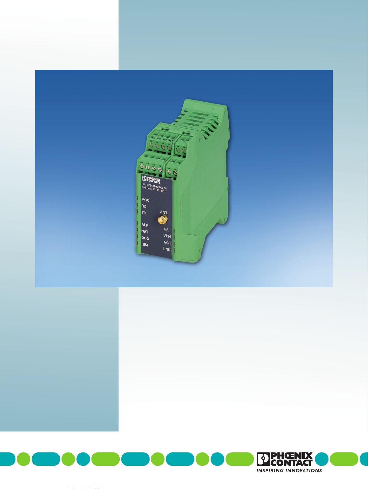
1 Description of the GSM modem...............................................................................................1-1
1.1 Description .........................................................................................................1-1
1.2 Ordering data .....................................................................................................1-2
1.3 Technical data ....................................................................................................1-2
2 Hardware installation ...............................................................................................................2-1
2.1 Housing dimensions ...........................................................................................2-1
2.2 Mounting the module on a DIN rail .....................................................................2-1
2.3 Description of the connections and LEDs...........................................................2-2
2.4 Establishing connections....................................................................................2-3
2.4.1 Safety notes ......................................................................................2-3
2.4.2 Connecting Ethernet networks ............................................................2-4
2.4.3 Connecting the antenna ......................................................................2-5
2.4.4 Inserting the SIM card .........................................................................2-6
2.4.5 Connecting the supply voltage ............................................................2-7
2.4.6 Connecting switching inputs and outputs ............................................2-8
2.5 Resetting the modem (reset) ..............................................................................2-9
3 Configuration via WBM ............................................................................................................3-1
3.1 Connection requirements ...................................................................................3-1
3.2 Starting web-based management (WBM) ..........................................................3-1
3.3 Device Information (View device status).............................................................3-3
3.3.1 Hardware ............................................................................................3-3
3.3.2 Status ..................................................................................................3-4
3.4 Local Network (Set up local network) .................................................................3-6
3.4.1 IP Configuration (Set up connection) ..................................................3-6
3.5 Wireless Network (Mobile phone settings) .........................................................3-7
3.5.1 GSM ...................................................................................................3-7
3.5.2 GPRS/EDGE .......................................................................................3-9
3.5.3 PING .................................................................................................3-10
3.5.4 Remote Configuration (Remote maintenance) ..................................3-11
3.6 Network Security (Security settings).................................................................3-12
3.6.1 Firewall (Definition of firewall rules) ...................................................3-12
3.6.2 NAT Table (Addressing table setup) .................................................3-15
3.7 VPN ..................................................................................................................3-16
3.7.1 IPsec Connections (IPsec connection setup) ....................................3-17
3.7.2 IPsec Certificates (Certificate upload) ...............................................3-22
3.7.3 IPsec Status (Status of the VPN connection) ....................................3-24
3.8 System .............................................................................................................3-25
3.8.1 User (Password modification) ...........................................................3-25
3.8.2 Additional AT commands ..................................................................3-26
3.8.3 RTC (Time and date setup) ...............................................................3-27
3.8.4 Reboot (Modem restart) ....................................................................3-29
3.8.5 Firmware Update ..............................................................................3-30
3.9 CIDR (Classless Inter-Domain Routing) ...........................................................3-31

PSI-MODEM-GSM/ETH
ii PHOENIX CONTACT 103965_en_00
4 Creating certificates.................................................................................................................4-1
4.1 Installing XCA .....................................................................................................4-1
4.2 Creating a database ...........................................................................................4-1
4.3 Creating a CA certificate.....................................................................................4-3
4.4 Creating machine certificates .............................................................................4-7
4.4.1 Creating templates ..............................................................................4-7
4.4.2 Creating machine certificates based on a template ...........................4-11
4.4.3 Exporting machine certificates ..........................................................4-14
5 Application examples for secure VPN connections..................................................................5-1
5.1 Modem-to-modem connection via GPRS/EDGE ................................................5-1
5.1.1 Setting up modem 1 ............................................................................5-1
5.1.2 Setting up modem 2 ............................................................................5-4
5.2 Connection from a modem to a control center via GPRS/EDGE
and the Internet ..................................................................................................5-5
5.2.1 Loading certificates on the modem .....................................................5-5
5.2.2 Loading certificates on the FL MGUARD RS VPN ..............................5-8
5.2.3 Setting a packet filter on the FL MGUARD RS VPN ..........................5-10
5.2.4 Setting up the VPN connection in mGuard ........................................5-10
5.2.5 Checking the status of the VPN connection in mGuard .....................5-13

Description of the GSM modem
103965_en_00 PHOENIX CONTACT 1-1
1 Description of the GSM modem
1.1 Description
The PSI-MODEM-GSM/ETH GSM modem is a high-performance modem for industrial
Ethernet networks, which can be used to transmit sensitive data securely via GSM
networks. The integrated firewall and the VPN support (Virtual Private Network) protect your
application against unauthorized access.
Remote stations can be integrated into an IP network via a GPRS/EDGE connection or by
dialing the phone number. The quad band technology means that the modem can be used
globally in all 850, 900, 1800, and 1900 MHz GSM networks.
No matter where your system or controller is located – the process data is available at any
location via a secure VPN connection.
For reliable and safe communication, the focus is on EMC, electrical isolation, and surge
protection.
In addition, the GPRS/EDGE service and GSM network quality are monitored. If necessary,
a corresponding message is sent or the GSM connection is reestablished.
Features
– Quad band (850 MHz/900 MHz/1800 MHz/1900 MHz)
–GPRS(General Packet Radio Service) and EDGE (Enhanced Data Rates for GSM
Evolution)
– Integrated TCP/IP stack
– Virtual permanent line for connecting networks via GPRS
– Integrated firewall
– VPN support
– Wide supply voltage range of 10 V DC to 30 V DC
– Temperature range of -25°C to +60°C
– High-quality electrical isolation (VCC // Ethernet)
– Integrated surge protection
– Easy configuration via web-based management (WBM)

PSI-MODEM-GSM/ETH
1-2 PHOENIX CONTACT 103965_en_00
1.2 Ordering data
1.3 Technical data
Modem
Description Type Order No. Pcs./Pkt.
Quad band modem for GPRS/EDGE and GSM with Ethernet interface,
firewall, VPN support, and alarm inputs and outputs
PSI-MODEM-GSM/ETH 2313355 1
Accessories
Description Type Order No. Pcs./Pkt.
GSM quad band antenna with omnidirectional characteristics PSI-GSM-QB-ANT 2313155 1
Antenna cable with SMA circular connector
Degree of protection
Dimensions
2 m
IP65
76 mm x 20 mm
GSM stub antenna for installation directly on the device, angled antenna
connector (90°, SMA circular connector)
PSI-GSM-STUB-ANT 2313342 1
System power supply unit,
primary-switched
Input voltage range
Nominal output voltage
Nominal output current
45 Hz ... 65 Hz
85 V AC ... 264 V AC
24 V DC ±1%
1.5 A
MINI-SYS-PS-100-240AC/24DC/1.5 2866983 1
DIN rail connector (3 required) ME 17,5 TBUS 1,5/ 5-ST-3,81 GN 2709561 1
Power supply
Supply voltage 10 V DC ... 30 V DC
Via COMBICON plug-in screw terminal block
24 V DC ±5% (alternative or redundant, via backplane bus contact and system
power supply)
Frequency DC
Current consumption
Nominal current consumption
Standby current consumption
< 360 mA at 24 V
< 90 mA at 24 V
LED indicator VCC (green LED)
Steady light: Operation
Ethernet interface
Connection method RJ45 female connector, shielded
Transmission speed 10/100 Mbps
Transmission length 100 m (twisted pair, shielded)
Supported protocols TCP/IP, UDP, TFTP, HTTP, MODBUS TCP, PPP, PROFINET, EtherNet IP,
CHAP
Secondary protocols ARP, DHCP, BOOTP, SNMP, RIP, RARP
LED indicator/data indicator TD (yellow LED), GSM data to modem (dynamic)
RD (green LED), GSM data from modem (dynamic)
LED indicator/control signal indicator ACT (yellow LED), Ethernet data transmission
LINK (green LED), Ethernet link established
Function
Management Web-based management, SNMP

Description of the GSM modem
103965_en_00 PHOENIX CONTACT 1-3
GSM/GPRS
Frequencies 850 MHz, 900 MHz, 1800 MHz, 1900 MHz (EGSM)
Transmission power 2 W at 850 MHz and 900 MHz
1 W at 1800 MHz and 1900 MHz
SIM interface 1.8 V and 3 V SIM card
GPRS compatibility GPRS Class 12, Class B
Coding scheme: CS1 ... CS4
EDGE EDGE (EGPRS) multislot Class 10
Network function 4 time slots for receiving data
4 time slots for transmitting data,
maximum of 5 simultaneous time slots
The PIN code is saved in the modem. After a voltage interrupt, the modem
automatically redials into the network and automatically logs into the GPRS
network.
Integrated TCP/IP stack, firewall, and VPN support, automatic connection
establishment.
Command set compatibility AT standard command set and extended
V.250 basic command set
Antenna connection 50 Ωimpedance SMA female antenna connector
LED SIM (red LED)
– Steady light: No SIM card present
– Flashing: No PIN code entered
– OFF: SIM card present and PIN code entered
NET (yellow LED)
– Steady light: Very good network reception
– Flashing: Good network reception
– Flashing quickly: Moderate network reception
– OFF: No network reception
Startup diagnostics Selftest, visualization via LEDs
(controller, RAM, EPROM, GSM engine, antenna, EEPROM)
Network test Network bargraph in web-based management
General data
Ambient temperature range (operation) -25°C ... +60°C
Housing
Material
Dimensions (H x W x D)
ME 35 with 5-pos. bus contact and ground contact
PA 6.6-FR, V0, green
99 mm x 35 mm x 120 mm
Weight of device 237 g
Functional earth ground Housing contact with DIN rail
Degree of protection IP20
Separate ground levels Supply // Ethernet (TP) // antenna
Vibration resistance According to DIN EN 60068-2-6
5g, 1.5 h each in x, y, and z direction
Shock test
Operation
Storage
According to DIN EN 60068-2-27
15g, 11 ms, half-sine shock pulse
30g, 11 ms, half-sine shock pulse
Free fall According to IEC 60068-2-32 from a height of 1 m (without packaging)
Test voltage 1.5 kV AC, 50 Hz, 1 min. between all ground levels according to
DIN EN 61010-1/VDE 0411-1 and DIN EN 60950
CE conformance According to R&TTE Directive 1999/5/EC

PSI-MODEM-GSM/ETH
1-4 PHOENIX CONTACT 103965_en_00
Electromagnetic compatibility
Noise immunity according to EN 61000-6-2
Electrostatic discharge (ESD) EN 61000-4-2 Criterion B
8 kV air discharge
6 kV contact discharge
Electromagnetic HF field
Amplitude modulation
Pulse modulation
EN 61000-4-3 Criterion A
10 V/m
10 V/m
Fast transients (burst)
Signal
Power supply
EN 61000-4-4
Criterion A
1 kV/5 kHz
Criterion A
1 kV/5 kHz
Criterion B
2 kV/ 5 kHz
Surge current load (surge)
Signal
Power supply
EN 61000-4-5 Criterion B
1 kV
2 kV
Conducted interference EN 61000-4-6 Criterion A
10 V
Noise emission EN 55011 Class A
CE conformance according to R&TTE Directive 1999/5/EC
EMC
Noise immunity
(electromagnetic compatibility)
EN 61000-6-2 Generic standard for the industrial
sector
Safety
Protection of personnel with regard to electrical safety EN 60950
Health
Limitation of exposure of the population to electromagnetic fields EC Gazette 1999/519/EC EC Council recommendation of
July 12, 1999
Radio
Effective use of the frequency spectrum and prevention of radio interference DIN EN 301511

Hardware installation
103965_en_00 PHOENIX CONTACT 2-1
2 Hardware installation
2.1 Housing dimensions
Figure 2-1 Housing dimensions (in mm)
2.2 Mounting the module on a DIN rail
•Mount the modem on a 35 mm EN DIN rail (see Figure 2-2).
Figure 2-2 Mounting
NOTE:
Only mount and remove the modem when the power supply is disconnected.
NOTE:
The DIN rail must be connected to PE to ensure safe operation.
103965A001
120 35
99
PSI-MODEM-GSM/ETH
Ord.-No. 23 13 355
LAN
VCC
RD
TD
ALR
NET
DCD
SIM
AA
VPN
ACT
LNK
ANT
102678A002

PSI-MODEM-GSM/ETH
2-2 PHOENIX CONTACT 103965_en_00
2.3 Description of the connections and LEDs
Connection terminal blocks
1Connection terminal blocks (COMBICON): 24 V power supply, 0 V power supply
26 switching inputs, digital
34 switching outputs, digital
Connectors
4SMA female antenna connector
5RJ45, Ethernet interface (TP port)
LEDs
VCC (Green) Steady light if supply voltage is present
RD (Yellow) Receive data with reference to the GSM connection
TD (Green) Transmit data with reference to the GSM connection
ALR (Red) Steady light if alarm message was sent successfully
Flashes when alarm message is being sent
Flashes quickly if alarm message could not be sent
OFF if no alarm is present
NET (Yellow) Steady light for very good network reception
Flashes for good network reception
Flashes quickly for moderate network reception
OFF if there is no network reception or reception is very poor
SIM (Red) No SIM card; flashes if no PIN code has been entered
AA (Yellow) Automatic answer, flashes during selective call acceptance
VPN (Green) VPN tunnel active
ACT (Yellow) Ethernet data transmission
LINK (Green) Ethernet link established
Beneath the cover
6SIM card holder
Reset button
3
12
4
6
PSI-MODEM-GSM/ETH
Ord.-No. 23 13 355
LAN
VCC
RD
TD
ALR
NET
DCD
SIM
AA
VPN
ACT
LNK
ANT
5

Hardware installation
103965_en_00 PHOENIX CONTACT 2-3
2.4 Establishing connections
2.4.1 Safety notes
WARNING: Electrical connection may only be carried out by qualified personnel
Only qualified personnel may connect the power, start up, and operate this device.
According to the safety instructions in this text, qualified personnel are persons who are
authorized to start up, to ground, and to mark devices, systems, and equipment according
to the standards of safety technology. In addition, these persons must be familiar with all
warning instructions and maintenance measures in this text.
Disregarding this warning may result in damage to equipment and/or serious personal
injury.
WARNING: SELV operation
The PSI-MODEM-GSM/ETH is designed exclusively for SELV operation according to
IEC 60950/EN 60950/VDE 0805.
WARNING:
The modem must only be connected to devices, which meet the requirements of
EN 60950 ("Safety of Information Technology Devices").
WARNING: Disconnect the device power supply before replacing the SIM card.
The device only supports 1.8 and 3 V SIM cards. For older SIM cards, please contact your
GSM service provider.

PSI-MODEM-GSM/ETH
2-4 PHOENIX CONTACT 103965_en_00
2.4.2 Connecting Ethernet networks
The PSI-MODEM-GSM/ETH has an Ethernet interface on the front in RJ45 format, to which
only twisted pair cables with an impedance of 100 Ωcan be connected.
•Push the Ethernet cable with the crimped RJ45 connector into the LAN interface until it
engages with a click.
Please observe the keying of the connector.
Figure 2-3 RJ45 interface
The RD and TD LEDs indicate the status of the Ethernet connection.
WARNING:
The modem must only be connected to devices, which meet the requirements of
EN 60950 ("Safety of Information Technology Devices").
NOTE:
Only use shielded twisted pair cables and corresponding shielded RJ45 connectors.
Table 2-1 Meaning of the terminal designations
Designation Meaning
TD (transmit data) Transmit data (refers to PC, PLC, etc.)
RD (receive data) Receive data (refers to PC, PLC, etc.)
RD (Yellow) Receive data with reference to the GSM connection
TD (Green) Transmit data with reference to the GSM connection
P i n 1
P i n 2
P i n 3
P i n 4
P i n 5
P i n 6
P i n 7
P i n 8
R D +
R D -
T D +
T D -
n . c .
n . c .
n . c .
n . c .
R J 4 5

Hardware installation
103965_en_00 PHOENIX CONTACT 2-5
2.4.3 Connecting the antenna
Figure 2-4 Antenna connection with SMA connector
•Connect a suitable antenna to the antenna connection.
•If the "NET" LED indicates good (flashing) or very good reception (steady light), secure
the antenna.
Installing the antenna
•Select an antenna position with a good wireless network signal. The "NET" LED can be
used to determine the receive quality.
•When using the PSI-GSM-900/1800-ANT antenna (Order No. 2708902), drill a hole
measuring 16.5 mm in diameter in the top of the control cabinet.
•Secure the antenna using the washer and nut provided:
Figure 2-5 PSI-GSM-900/1800-ANT antenna installation
NOTE: Please observe the following during installation:
– The antenna has a diameter of 76 mm and is 21 mm high.
– The cable is 2 meters long.
VCC
RD
TD
ALR
NET
DCD
SIM
AA
VPN
ACT
LNK
ANT
PSI-MODEM-GSM/ETH
Ord.-No. 23 13 355
102678A005

PSI-MODEM-GSM/ETH
2-6 PHOENIX CONTACT 103965_en_00
2.4.4 Inserting the SIM card
Figure 2-6 Opening the housing
Opening the housing Open the housing to access the SIM card holder inside.
•Using a screwdriver, lever off the LAN connection cover.
Inserting the SIM card Your GSM service provider will have supplied you with a SIM card where all the important
data for your connection is stored.
•If you have been supplied with a SIM card in credit card format, simply detach the small
section of the card and remove any excess plastic from the edges.
•With the contact surface facing the PCB, slide the SIM card into the holder. The angled
corner should point upward (see Figure 2-6).
PIN code The SIM card can be protected with a 4 or 5-digit PIN code.
When selecting the SIM card, please note that a packet data connection (GPRS or EDGE)
is required for the core functions (VPN router).
WARNING: Disconnect the device power supply before replacing the SIM card.
The device only supports 1.8 and 3 V SIM cards. For older SIM cards, please contact your
GSM service provider.
NOTE: Electrostatic discharge
The module contains components that can be damaged or destroyed by electrostatic
discharge. When handling this module, observe the necessary safety precautions against
electrostatic discharge (ESD) according to EN 61340-5-1 and EN 61340-5-2.
A
LAN
NET
DCD
SIM
AA
VPN
ACT
LNK
LAN
NET
DCD
SIM
AA
VPN
ACT
LNK
C
B
7174B012
It is recommended that you enter the PIN code as described in "User (Password
modification)" on page 3-25.

Hardware installation
103965_en_00 PHOENIX CONTACT 2-7
2.4.5 Connecting the supply voltage
The supply voltage must be between 10 V DC and 30 V DC.
•Connect the 24 V supply voltage to the "24V" and "0V" terminal points on the plug-in
screw terminal block.
As soon as the "VCC" LED lights up, the modem is ready.
Figure 2-7 Connecting the supply voltage
WARNING: The PSI-MODEM-GSM/ETH is designed exclusively for SELV operation
according to IEC 60950/EN 60950/VDE 0805.
O1 O2
24V 0V I1 I2
O3 O4
I3 I4 I5 I6
I3 I4 I5 I6
O1 O2
24V 0V I1 I2
O3 O4
24 V
0V

PSI-MODEM-GSM/ETH
2-8 PHOENIX CONTACT 103965_en_00
2.4.6 Connecting switching inputs and outputs
Figure 2-8 Wiring the inputs
•Connect the switching inputs and outputs to the relevant plug-in screw terminal blocks.
– 10 ... 30 V DC can be connected to the floating switching inputs (IN1 ... IN6).
– The short-circuit-proof switching outputs (O1 ... O4) are designed for a maximum
of 50 mA at 10 ... 30 V DC.
•The 0 V potential of the switching inputs and outputs must be connected to the "0 V"
terminal block of the power supply connection.
NOTE: The switching outputs are only enabled in software release 1.xx or later.
They are not available in earlier versions.
I3 I4 I5 I6
O1 O2
24V 0V I1 I2
O3 O4
-
+
This manual suits for next models
1
Table of contents
Other Phoenix Contact Modem manuals