Wood and Douglas 1300 User manual

HERMES RADIO MODEM
OPERATING INSTRUCTIONS
(1892 1300)
SPECIALIST RF DESIGNS
© Copyright Wood & Douglas 2002
Version: 1.3
Issue: July 2002
LATTICE HOUSE
BAUGHURST
BASINGSTOKE
UK RG26 5LP
Tel: +44 (0) 118 981 1444 Fax: +44 (0) 118 981 1567

Table Of Contents
1INTRODUCTION ..............................................4
2CONNECTIONS & INDICATIONS .................................5
2.1 RS232 Connector .......................................5
2.2 Power Connector ........................................6
2.3 RF Connector ...........................................6
2.4 Front Panel Indications ...................................6
3MODEM OPERATION ..........................................7
3.1 Introduction ............................................7
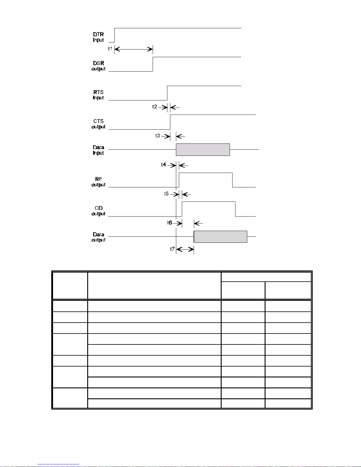
3.2 Handshaking Operation During Transmit and Receive .........7
3.3 Data Transfer Modes .....................................8
3.4 RS232 Data Handling ....................................8
3.5 Receive-to-Transmit Turnround ............................8
4LIST OF COMMANDS: ........................................10
4.1 Command Mode ........................................10
4.1.1 Activation of the Command Mode: .....................10
4.1.2 Ending of Command Mode ..........................11
4.2 Command Syntax ......................................11
4.3 Baud Rate (AT B0) ......................................12
4.4 Parity (ATB1) ..........................................12
4.5 Format Mode (AT F) .....................................13
4.6 Engineering Test Modes (AT In) ...........................14
4.7 Software Version Information (AT I9) .......................15
4.8 Command Mode Guard Time (AT S154) .....................15
4.9 Centre Radio Frequency (AT S155) ........................15
4.10 Received Signal Strength Indication (RSSI) (AT S156) ........16
4.11 Radio Channel (AT S157) ................................17
4.12 Data Quality (AT S158) ..................................17
4.13 Squelch (AT S159) ......................................18
4.14 Transmission Power (AT S160) ...........................19
4.15 Channel Step Size (AT S161) .............................20
4.16 Test Message Period (AT S162) ...........................20
4.17 Over-Air Symbol Rate (AT S163) ..........................21
4.18 Preamble Period (AT S165) ...............................21
4.19 Frame Synch Tolerance (AT S166) .........................22
4.20 Invert Symbol (AT S167) .................................22
4.21 Squelch Delay (AT S168) .................................23
4.22 Enable/Disable Receive Output Data (AT &D) ...............23
4.23 Enable/Disable Input Echo Data (AT &E) ...................23
4.24 Radio Frequency (AT &F) ................................24
4.25 Save parameters (AT &W) ................................24
4.26 Restore defaults (AT &Y8) ...............................24
4.27 Display parameters (ATT?) ...............................25
4.28 Code Loader (AT S2000) .................................26

Hermes Operator Note Page 3 of 32
5HARDWARE SPECIFICATION ..................................28
5.1 Introduction ...........................................28
5.2 RS232 Port Parameters ..................................28
5.3 Radio Specifications ....................................29
6MECHANICAL SPECIFICATION ................................30
6.1.1 Casting Enclosure .................................30
6.1.2 3U Rack Mounting Enclosure .........................30
6.2 Operating conditions ....................................32
6.3 Vibration Specifications: .................................32
6.4 Type Approvals ........................................32
LIST OF FIGURES
Figure 1 Timing Information ..........................................9
Figure 2 Front View of Casting ......................................31
Figure 3 Rear View of Casting .......................................31
Figure 4 3U Enclosure .............................................31
LIST OF TABLES
Table 1 Data Connections ...........................................5
Table 2 Power Connections ..........................................6
Table 3 Timing Data ................................................9
Table 4 RSSI Levels ...............................................16
Table 6 Squelch Levels ............................................18
Table 7 Power Levels for G-MAX Radios ...............................19
Table 8 Power Levels for SXn50 Radios ...............................19

Hermes Operator Note Page 4 of 32
1INTRODUCTION
This document describes the operation of the Wood and Douglas Hermes
Radio Modem.
The Hermes modems provide a transparent data link for a wide range of
applications. The internal modem can be used with a range of Wood &
Douglas RF products to give great choice in the operating frequency and
transmit power. Two enclosure types are available to suit different
applications.
The Hermes uses 4-Level Frequency Shift Keying (FSK) technology to
achieve a RF link data rate of 19,200 baud in a 25kHz channel spacing and
9,600 baud in a 12.5kHz channel spacing.
One of the radio transceivers (the G-Max family) used inside the Hermes is
designed for harsh environments and operates over a wide temperature
range and a high vibration environment.
The standard Hermes is fitted with the SXn50 range of transceivers. This
family has products at VHF, UHF and 868MHz, with a maximum transmit
power of 500mW.

Hermes Operator Note Page 5 of 32
2CONNECTIONS & INDICATIONS
2.1 RS232 Connector
The RS232 connections are made via a 9 way D female with the following
connections:
Pin No. Function
1CD Output
Set (+ve) when a RF signal above a certain level is present at the
RF connector. The threshold is programmable over 10 levels that
are defined in section 5.13
2RXD RS232 data level data output
3TXD RS232 level data input
4DTR RS232 level input
When set (+ve) by the DTE (host processor) the modem and
transceiver is turned on. The max/min levels are:
DTR Vin Min. (off state) =-15V
DTR Vin Max. (off state) =+2.5V
DTR Vin Min (on state) =+5V
DTR Vin Max (on state) =+15V
DTR Iin Max(on state) =4mA
5Signal Ground
6DSR RS232 level output
Set (+ve) after power is applied to the modem or when the DTE
(host processor) sets DTR +ve. The output is active when the
modem is ready to receive data. The time taken for the output to
become active is <50ms from when DSR or power is applied to
the modem.
7RTS RS232 level input
The RTS input must be set (+ve) for both data and configuration.
Data is ignored when RTS is clear (-ve).
8CTS RS232 level output
Set (+ve) if the transmit RS232 data into the modem can be
accepted and the RTS input is set, it is cleared (-ve) otherwise.
Clearing of this signal indicates that the input transmit buffer is
nearly full .The RS232 data must be stopped within 10 bytes of
this signal being cleared. After this point the data is ignored. The
CTS signal is set again if there is room for more than 10 bytes.
9n/c Table 1 Data Connections

Hermes Operator Note Page 6 of 32
2.2 Power Connector
The power and ancillary connections are made via a 9 way D male
connector. The power supply input is fully isolated from the chassis of the
module.
Note: The power supply cannot be used as an RS232 input line.
Pin No. Function
1RSSI Received Signal Strength Output
Analogue output proportional to the level of the RF input
Level at -110dBm input = ~0.6V and at -60dBm = ~2.1V
2n/c
3, 4 +ve Supply Input (9 - 36VDC)
Receive current <100mA at 24VDC input
Transmit current <400mA at 1000mW RF output, 24VDC input
(reverse voltage protection with re-settable "polyfuse")
5Power Supply Ground (isolated from enclosure)
6I2C Bus Clock (engineering use only)
70V (chassis of enclosure)
8I2C Bus Data (engineering use only)
9Power Supply Ground (isolated from enclosure)
Table 2 Power Connections
2.3 RF Connector
The RF connection to the modem is a female TNC bulkhead connector.
2.4 Front Panel Indications
There are 3 LED indicators which show the operation of the unit as follows:
PGreen Power On when DC supply input present and DTR input
is high (> 3V)
SOrange Status Flashes orange when the transceiver is switched
to transmit or receive. Continuous orange if the
transceiver goes “Out Of Lock” (OOL) which
happens on failure, or when an invalid frequency
is programmed into it.
TRed TX On when the transmitter is turned on.
These LEDs are next to the connectors on both types of enclosure.

Hermes Operator Note Page 7 of 32
3MODEM OPERATION
3.1 Introduction
The internal modem power supply system is turned on/off with the DTR
input. The modem is ready after an initialisation period. The modem enters
receive mode using the last set of configuration parameters (RF channel,
squelch level etc).
The modem starts the transmit sequence after the first data byte is received
from the RS232 port. The incoming data is stored while the transmitter is
turned on and the preamble output. The start, stop and parity (if 8 bit data)
are stripped off the input data stream and the data stored as 8 bits only.
The transmission is ended when the input buffer is empty. After the
transmission is complete and the transmitter turned off, the modem
switches back to receive mode. Transmission has priority over reception so
the user has to check by means of the CD handshake line if the radio
channel is free before inputting data.
The timing of the power, handshaking and data transfer is shown in Figure 1
for the G-MAX radio (running at 9600 baud over-air in a 12.5kHz channel)
and for the SXn50 series of radios (running at 19,200 baud over-air in a
25kHz channel).
3.2 Handshaking Operation During Transmit and Receive
The DTE must set the RTS input for the modem to accept data. The RTS
input can be set continuously if no hardware handshake lines are available
on the DTE. The CTS line must be monitored for data packets greater than
256 bytes to ensure that input buffer overflow does not occur. If the data
input is not stopped within 10 characters from the point of buffer overflow,
the input data will be discarded.
Handshaking is also required during the code loading.
The modem starts transmitting when the data is input, regardless of the
state of the CD output. The DTE must check the CD output prior to data
transmission. When the CD output is set this indicates that a RF signal is
present at the antenna. This output is only active when the modem is not
transmitting.

Hermes Operator Note Page 8 of 32
3.3 Data Transfer Modes
In FEC mode every byte of the data, including the "end-of-file" string is
scrambled within the modem to ensure that the error correction mechanism
operates over non-consecutive bits in the data stream. The frame sync
pattern is not scrambled.
In non-FEC (High Speed) mode the data is scrambled to minimise problems
that could occur with many consecutive 1's or 0's in the input data stream.
3.4 RS232 Data Handling
The over-air data rate is faster than the input data rate because only the 8
data bits of the input character of 11 bits are transmitted. To ensure that no
data is lost at the output, and for the modem to transmit the data in one
continuous packet it is essential that the input and output data rates are set
to at least 2 x the over-air-baud rate. The default over-air baud rate for this
modem working in a 12.5kHz channel is 9600 baud. For this set the input
and output RS232 data rates to 19,200. For a 25kHz channel, with an over-
air baud rate of 19,200, set the data rates to 38,400 baud.
Some applications running under the Windows™ operating system output
the data with gaps between single or groups of characters. In some cases
this can reduce the character rate below the over-air data rate. When this
occurs, the system will assume that the input data has finished and will turn
the transmitter off when the input data buffer is empty.
If more characters are input to the modem while the transmitter is being
turned off, the transmit process will re-start. This will appear as bursts of
RF close together. At the receive end, the timing of the data will change as
there will be gaps in the received data stream.
This mode of operation ensures that small data packets are transmitted in
as short a time as possible to reduce the on-air time to a minimum.
3.5 Receive-to-Transmit Turnround
After the last character of a packet of data is output from the receiver, the
receive system is still processing the “end-of-packet” data. This takes ~5ms
when in non-FEC mode and ~10ms in FEC mode. During this period the
processor does not accept any input data. The figures apply for default
settings: 19,200 baud rate and 4800 symbol/sec over-air baud rate

Hermes Operator Note Page 9 of 32
Figure 1 Timing Information
Function Description Time (ms)
G-MAX
(9600 baud) SXn50
(19200 baud)
t1 DTR input-to-modem DSR output <90 <90
t2 RTS input to CTS output <0.5 <0.5
t3 CTS output to Data input >0.1 >0.1
t4 Data input to RF output (non-FEC mode) <25 <25
Data input to RF output (FEC mode) <25 <25
t5 RF output to CD output (at RX end) <5 <2.5
t6 CD output to data output (non-FEC mode) <30 <30
CD output to data output (FEC mode) <50 <45
t7 Data input to Data output (non-FEC mode) <50 <45
Data input to Data output (FEC mode) <75 <55
Table 3 Timing Data

Hermes Operator Note Page 10 of 32
4LIST OF COMMANDS:
4.1 Command Mode
The modem is configurable through the RS232 port. The Command Mode
has to be activated to do this, as detailed in the following paragraphs:
4.1.1 Activation of the Command Mode:
The Command Mode is activated with the string:
<wait>+++<wait> <CR><LF>
Where <wait> is a programmable period after transmitting data (which is set
by register S154) which has a nominal value of 10ms.
The modem responds with:
OK<CR><LF>
The modem is now ready to be configured. Transmitting or reception is
blocked during Command Mode.
If the "+++" string is input without a <CR><LF> then the string is transmitted
as normal data. Note that one or more consecutive “+” characters in the
input data are held in the modem until it is determined that it is not a “+++”
string.
The configuration mode is only accepted if the RTS line is set. The “+++”
string is only accepted if this string is the first three characters and there has
been no data for greater than the time set by register S154.
The +++ string is only transmitted over the air if embedded in a data string as
described above.
Important: any configuration changes made are only saved to the
non-volatile memory after a write command (AT &W).
Note that the communication parameters (baudrate etc) are the programmed
parameters.

Hermes Operator Note Page 11 of 32
4.1.2 Ending of Command Mode
The command mode is ended by inputting the string:
ATO<CR><LF>
The modem responds with:
OK<CR><LF>
The modem is now ready for normal modem operation.
Note that the communication parameters (baudrate etc) are the programmed
parameters.
4.2 Command Syntax
4.2.1 Note: Capital letters MUST be used for all command instructions.
4.2.2 All syntax commands with multiple ‘n’ ‘s accept multiple formats. For
example, if ‘nnn’ is specified in the command string, then the following will
be valid:
1or +1
01 or +01
001 or +001
4.2.3 The commands for reading registers have the form:
AT S158?<CR><LF>
The answer to this query is:
nnn<CR><LF>
4.2.4 After setting a parameter the modem responds with:
OK<CR><LF> if a valid entry and
ERROR<CR><LF> if an invalid entry

Hermes Operator Note Page 12 of 32
4.3 Baud Rate (AT B0)
When the baud rate is changed, the change is made after the Command
Mode is ended (with the AT O command).
The baud rate is set with the following command:
Baud Rate AT B0=n <CR><LF>
Where: n = 1 4800
n = 2 9600
n = 3 19200
n = 4 38400
Default: n = 3 for 12.5kHz radios
n = 4 for 25kHz radios
Read: AT B0?<CR><LF>
Note: this shows the new value, even though the change is
not implemented until the Command Mode is exited.
Read Return: n<CR><LF>
Example: AT B0=2<CR><LF> for 9600 baud
4.4 Parity (ATB1)
The number of data bits is fixed to 8. Parity at the RS232 input to the
transmitter has no effect and is not transmitted. The 8 data bits can be used
to transmit 7 data bits + 1 parity bit. In this case the modem has to be set to
no parity.
The number of stop bits at the RS232 input to the transmitter can be 1 or
more. The number of stop bits at the receiver RS232 output is fixed at 1. This
is to avoid congestion of the output data.
When the parity is changed, the change is made after Command Mode is
ended (with the AT O command).
The parity is set with the following command:
Parity AT B1=n<CR><LF>
Where: n = 1 even
n = 2 odd
n = 3 none
Default: 3
Read: AT B1?<CR><LF>
Note: this shows the new value, even though the change is
not implemented until the Command Mode is exited.
Read Return: n<CR><LF>
Example: AT B1=n<CR><LF>

Hermes Operator Note Page 13 of 32
4.5 Format Mode (AT F)
This command turns the Forward Error Correction (FEC) mode on and off.
The over-air format allows for higher speed operation, but with reduced Bit
Error Rate (BER) performance with the FEC turned off, or lower speed,
improved BER with the FEC turned on.
Figure 1 and the associated table give the timing information for both modes
of operation.
The command is:
Format mode AT F=n<CR><LF>
Where n=0 mode with FEC
n=1 high speed mode without FEC
Default: n=1 (non-FEC mode)
Read: AT F?<CR><LF>
Read Return: n<CR><LF>
Example: AT F=1<CR><LF>

Hermes Operator Note Page 14 of 32
4.6 Engineering Test Modes (AT In)
Format modes:
To enable the function AT In=1 <CR><LF>
To disable the function AT In=0 <CR><LF>
Modem responds with OK <CR><LF>
Read status: AT In?<CR><LF>
Modem responds with m <CR><LF> where m=0, not active
m=1, active
Where n = 2 Output Continuous Preamble (used for
checking transmitter and receiver). The
preamble is transmitted until stopped by the
ATI2=0 or AT I=10 commands, or ending the
command mode. Note: for a G-Max, this test
must not be run for >10 minutes as damage to
the transceiver may occur.
n = 3 Output a series of 49 byte long data packets
with a programmed period between each
packet set with register S162. The message
data sent is: “The quick brown fox jumps over
the lazy dog.<CR><LF>” Each line of data is
pre-ceded by “XX “ where XX is a line number
which increments from 00 - 99.
The data is transmitted until stopped by the
ATI3=0 or AT I=10 commands, or ending
command mode.
n = 4 Adds the Output Data quality and Signal level
data to the end of each received data packet.
This is ended by the ATI4=0 or AT I=10
command. The data format is:
R:XX, D:XXX<CR><LF>
where XX = 1 - 10 and XXX = 66 - 256 as
defined in paragraphs 5.10 and 5.12
Note: if data is received before the values have
been read then R:XX, D:XXX<CR><LF> will be
output.
n = 9 Gives information about the software version
(refer to paragraph 5.7).
n = 10 Turn off test modes

Hermes Operator Note Page 15 of 32
4.7 Software Version Information (AT I9)
This command tells the modem to output information about the software
version.
Example: ATI9=1<CR><LF> return software version
or ATI9<CR><LF>
Return: ‘an ASCII string detailing the ID and versions of the
internal processors’ <CR><LF>
An example of the return data is as follows:
Files:
Main micro:"QL3z10", Ver.:1.01.05, Date:31/10/2001
Slave micro:"Slave",Ver.:0.00.02, Date:12/11/20001
Flash Programmer:"karfl3", Ver.:1.00.03, Date:24/10/2001
Hermes®, © 2001, Wood & Douglas Ltd.
4.8 Command Mode Guard Time (AT S154)
To enable the transmission of the command sequence within a packet of
data, a guard time is placed around the command sequence. If the gap
between the characters in the command mode string is less than this guard
time, then the data string is assumed to be part of the data. This includes
the gap between the last received data byte and the first “+”. The command
is:
AT S154=nnn<CR><LF>
Where nnn =0 to 255 ms
Default: 10
Read: AT S154?<CR><LF> read the setting
Read Return: nnn<CR><LF>
Example: AT S154=10<CR><LF> set 10 msec time delay
4.9 Centre Radio Frequency (AT S155)
The channel change system for the Hermes is based around a centre
frequency. The Hermes is programmed with a factory set centre frequency
that is the centre of the RF switching band. The channel change is carried
out by programming a channel step size (typically 12.5kHz) and setting 00-99
above or 00-99 channels below the centre frequency. The centre frequency
can be changed and stored in EEPROM for moving the programmed
channels. A temporary change can also be made by storing a new centre
frequency in RAM. This is not restored if power is lost to the unit.

Hermes Operator Note Page 16 of 32
The centre radio frequency of the modem is set as follows:
AT S155=nnn.nnnnnn<CR><LF>
Where: nnn.nnnnnn is the format of the input string for the
frequency in MHz
Default: current centre frequency.
Read: AT S155?<CR><LF>
Read Return: nnn.nnnnnn<CR><LF>
Example: AT S155=458.5<CR><LF> sets 458.5MHz
AT S155=458.500000<CR><LF> sets 458.5MHz
Note that frequencies in multiples of either 12.5kHz or 10kHz only are
acceptable. If a whole number of MHz is entered a “.” must be entered
before the <CR><LF>.
If the wrong centre frequency is entered the modem will respond with the
following error message and the entry will be ignored:
ERROR<CR><LF>
4.10 Received Signal Strength Indication (RSSI) (AT S156)
This request to the modem gives a response of nn <CR><LF>, where the nn
is the value of the Received Signal Strength of the radio carrier present at the
antenna at that time. The returned value of RSSI is in the range of 1 to 10.
The level of RF level of each value is given in the following table:
RSSI Level Level at RF Input ( dBm ±2dB)
01 -114 to -120
02 -108 to -114
03 -102 to -108
04 -96 to -102
05 -90 to -96
06 -84 to -90
07 -78 to -84
08 -72 to -78
09 -66 to -72
10 > -66
XX Not available
Table 4 RSSI Levels

Hermes Operator Note Page 17 of 32
The RSSI level is requested with the command:
AT S156?<CR><LF>
Read Return: nn<CR><LF>
The data can be added to the end of each received packet as defined in
paragraph 5.6.
4.11 Radio Channel (AT S157)
The radio transceiver is programmed with a centre frequency (using the AT
S155 command). This frequency is set up in the factory at the centre of the
RF switching bandwidth. Once programmed with this frequency a Channel
Step Size (using AT S161 command) can be programmed. ±99 channels
can then be set with this command to give a total of 199 frequencies.
The command for setting the radio channel is
AT S157=n<CR><LF>
Where: n = ±0 to ±99
Default: 0 (which is printed on screen as +00)
Read AT S157?<CR><LF>
Read Return: ±nn<CR><LF>
Example: AT S157=-10<CR><LF> sets the channel to -10
4.12 Data Quality (AT S158)
This request for data gives an indication of the quality of the data reception.
The signal quality is read from the modem system at the end of each
received packet and stored to give a consistent result when the quality is
requested. The value is in the range 64 to 255, the larger the value, the
higher the quality. The command for requesting the data quality is
AT S158?<CR><LF>
Read Return: nnn<CR><LF>
If no data has been received, XXX is returned.
The data can be added to the end of each received packet as defined in
paragraph 5.6.

Hermes Operator Note Page 18 of 32
4.13 Squelch (AT S159)
This command sets the squelch threshold to one of 10 pre-set levels as
shown in the Table 6.
This command enables the user to reduce the chances of local interference
showing the channel to be busy which could reduce the occupancy of the
system.
Squelch Level Level at RF Input
( dBm ±2dB)
1< -112
2-110 to -112
3-108 to -110
4-105 to -108
5-103 to -105
6-101 to -103
7-99 to -101
8-97 to -99
9-95 to -97
10 > -95
Table 6 Squelch Levels
The command for setting the squelch is
AT S159=n<CR><LF>
Where: n = squelch threshold with value 1 to 10
Default: 2
Read AT S159?<CR><LF>
Read Return: nn<CR><LF>
Example: AT S159=10<CR><LF> sets the squelch to 10

Hermes Operator Note Page 19 of 32
4.14 Transmission Power (AT S160)
The command enables the RF transmit power to be modified. Different RF
units have different capabilities and may change, depending on what is
supplied.
The SXn50 range of transceivers have 2 levels only. The levels for the 1W
and 2W versions of the G-MAX are shown in Table 7. Table 8 shows the 2
levels for the SXn50 range.
Power
Level
Output Power for 1W G-MAX Output Power for 2W G-MAX
mW
(nominal) dBm
(nominal) Tolerance
(dB) mW
(nominal) dBm
(nominal) Tolerance
(dB)
1 16 12 ±3 31 15 ±3
2 25 14 ±3 50 17 ±3
3 40 16 ±3 79 19 ±3
4 63 18 ±1.5 126 21 ±1.5
5 100 20 ±1.5 200 23 ±1.5
6 158 22 ±1.5 316 25 ±1.5
7 251 24 ±1.5 500 27 ±1.5
8 398 26 ±1.5 794 29 ±1.5
9 631 28 ±1.5 1260 31 ±1.5
10 1000 30 ±1.5 2000 33 ±1.5
Table 7 Power Levels for G-MAX Radios
Power
Level
Output Power
mW
(nominal) dBm
(nominal) Tolerance
(dB)
1 5 7 ±3
2 500 27 ±1.5
Table 8 Power Levels for SXn50 Radios

Hermes Operator Note Page 20 of 32
The power is set with the command:
AT S160=n<CR><LF>
Where: sets the power threshold <1 to 10>
Default: 10
Read AT S160?<CR><LF>
Read Return: nn<CR><LF>
Example: AT S160=-10<CR><LF> sets the power level to 10
4.15 Channel Step Size (AT S161)
This command sets the channel step size. The basic reference frequency for
the radio is either 12.5KHz or 10KHz, giving possible frequency channel
steps of 10kHz, 12.5kHz, 20kHz and 25kHz. The Channel Step Size is set
with the command:
AT S161=n<CR><LF>
Where: n=1 10 kHz
n=2 12.5 kHz
n=3 20 kHz
n=4 25 kHz
Default: n=2 (12.5 kHz)
Read: AT S161?<CR><LF>
Read Return: n<CR><LF>
Example: AT S161=1<CR><LF> sets 10 kHz channel step
If a channel step size is entered which is not a multiple of the centre
frequency an error is returned and the entry ignored. This is to ensure that
only valid frequencies on multiples of the channel step size are allowed
based on the centre frequency entered. The error message is of the form:
ERROR<CR><LF>
4.16 Test Message Period (AT S162)
This command sets the period between sending the test message. The
command is:
AT S162=n<CR><LF>
Where: n=1 - 255 in 10ms steps
Default: n=10 (100ms)
Read: AT S162?<CR><LF>
Read Return: nnn<CR><LF>
Example: AT S162=100<CR><LF> sets 1 second period
This manual suits for next models
2
Table of contents
Other Wood and Douglas Modem manuals
Popular Modem manuals by other brands

Lancom
Lancom 1781-4G Quick reference guide

Digicom
Digicom Tintoretto LAN Plus ISDN LAN Modem brochure

Seneca
Seneca Serie Z PC installation manual

NETGEAR
NETGEAR Telstra Wi-Fi 4G Advanced II AirCard 790S user manual

Paradyne
Paradyne COMSPHERE 3920PLUS Series installation instructions

D-Link
D-Link DSL-G225 Quick installation guide