Phoenix Contact CF 3000-2,5 User manual

User Manual
Stripping and crimping automat
for insulated ferrules in reel
packaging
UM EN CF 3000-2,5
Order No. 2888149


CF 3000
1-4 PHOENIX CONTACT 102649_en_02
Please observe the following notes
User group of this manual
The use of products described in this manual is oriented exclusively to qualified electricians
or persons instructed by them, who are familiar with applicable standards and other
regulations regarding electrical engineering and, in particular, the relevant safety concepts.
Explanation of symbols used and signal words
How to contact us
Internet Up-to-date information on Phoenix Contact products and our Terms and Conditions can be
found on the Internet at:
phoenixcontact.com
Make sure you always use the latest documentation.
It can be downloaded at:
phoenixcontact.net/products
Subsidiaries If there are any problems that cannot be solved using the documentation, please contact
your Phoenix Contact subsidiary.
Subsidiary contact information is available at phoenixcontact.com.
Published by PHOENIX CONTACT GmbH & Co. KG
Flachsmarktstraße 8
32825 Blomberg
GERMANY
Should you have any suggestions or recommendations for improvement of the contents and
layout of our manuals, please send your comments to:
This is the safety alert symbol. It is used to alert you to potential personal injury
hazards. Obey all safety measures that follow this symbol to avoid possible
injury or death.
There are three different categories of personal injury that are indicated with a
signal word.
DANGER This indicates a hazardous situation which, if not avoided, will
result in death or serious injury.
WARNING This indicates a hazardous situation which, if not avoided, could
result in death or serious injury.
CAUTION This indicates a hazardous situation which, if not avoided, could
result in minor or moderate injury.
This symbol together with the signal word NOTE and the accompanying text
alert the reader to a situation which may cause damage or malfunction to the
device, hardware/software, or surrounding property.
This symbol and the accompanying text provide the reader with additional
information or refer to detailed sources of information.

102649_en_02 PHOENIX CONTACT 1-5
General terms and conditions of use for technical documentation
Phoenix Contact reserves the right to alter, correct, and/or improve the technical
documentation and the products described in the technical documentation at its own
discretion and without giving prior notice, insofar as this is reasonable for the user. The
same applies to any technical changes that serve the purpose of technical progress.
The receipt of technical documentation (in particular user documentation) does not
constitute any further duty on the part of Phoenix Contact to furnish information on
modifications to products and/or technical documentation. You are responsible to verify the
suitability and intended use of the products in your specific application, in particular with
regard to observing the applicable standards and regulations. All information made
available in the technical data is supplied without any accompanying guarantee, whether
expressly mentioned, implied or tacitly assumed.
In general, the provisions of the current standard Terms and Conditions of Phoenix Contact
apply exclusively, in particular as concerns any warranty liability.
This manual, including all illustrations contained herein, is copyright protected. Any
changes to the contents or the publication of extracts of this document is prohibited.
Phoenix Contact reserves the right to register its own intellectual property rights for the
product identifications of Phoenix Contact products that are used here. Registration of such
intellectual property rights by third parties is prohibited.
Other product identifications may be afforded legal protection, even where they may not be
indicated as such.

CF 3000
6PHOENIX CONTACT 102649_en_02
Table of Contents
1 Basic instructions .......................................................................................................................7
1.1 Intended purpose .................................................................................................7
1.2 Work sites..............................................................................................................8
1.3 For your safety.......................................................................................................8
2 Description of the CF 3000 ........................................................................................................9
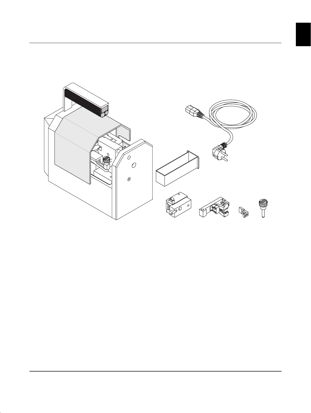
2.1 Scope of delivery ...................................................................................................9
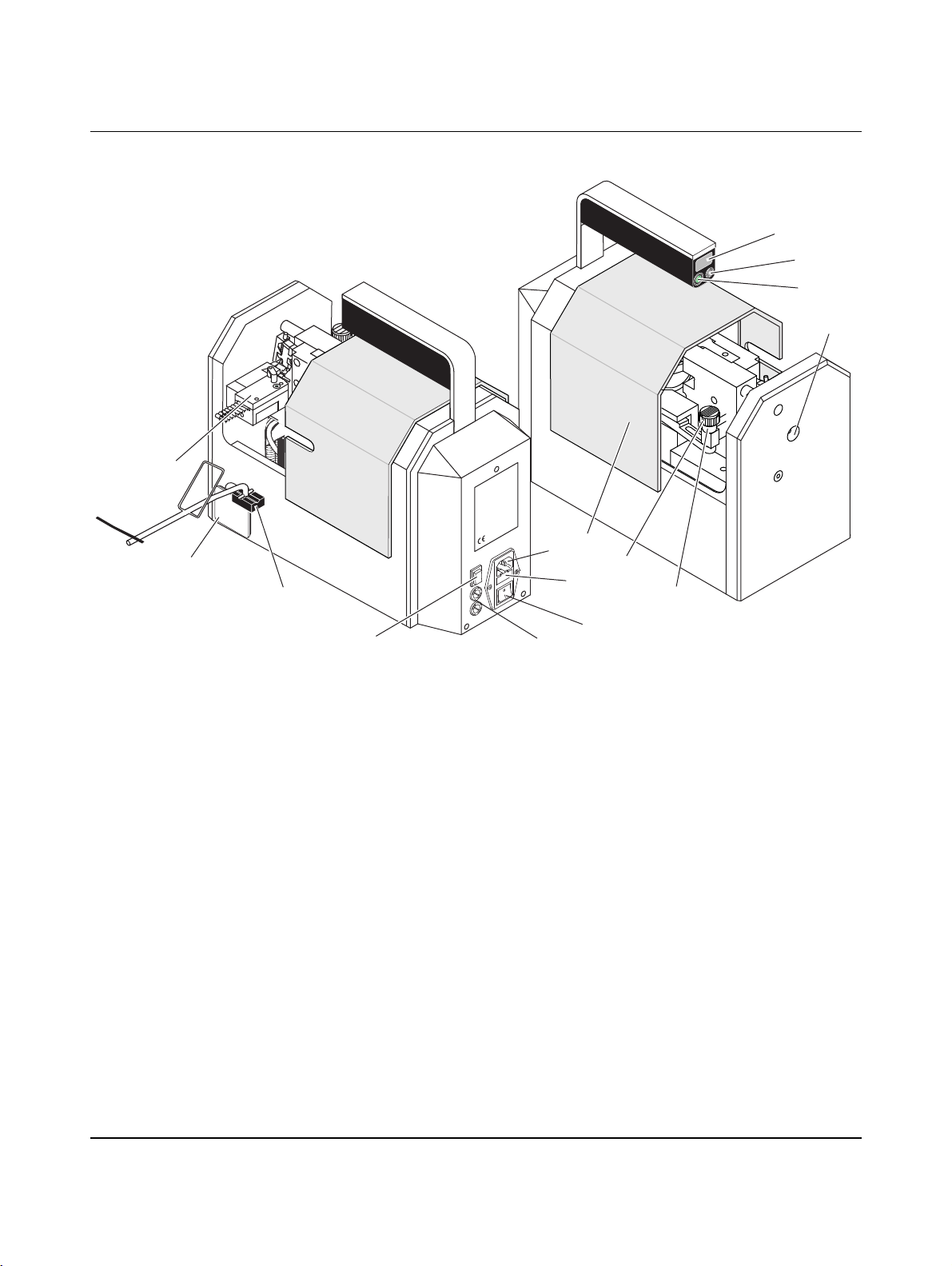
2.2 Overview of the operating components ...............................................................10
3 Putting into operation ...............................................................................................................11
3.1 Selecting the installation site................................................................................11
3.2 Preparing the dispenser.......................................................................................11
4 Operation .................................................................................................................................13
4.1 Stripping and crimping.........................................................................................13
4.2 Converting to other cross-sections ......................................................................14
4.3 Service ................................................................................................................16
5 Rectifying malfunctions ............................................................................................................17
5.1 Maintenance position...........................................................................................17
5.2 Fault cases ..........................................................................................................17
5.3 Fault case 1 .........................................................................................................17
5.4 Fault case 2 .........................................................................................................18
5.5 Fault case 3 .........................................................................................................18
5.6 Fault case 4 .........................................................................................................19
5.7 Fault case 5 .........................................................................................................19
5.8 Fault case 6 .........................................................................................................20
5.9 Fault case 7 .........................................................................................................20
A Technical Annex .......................................................................................................................21
A 1 Technical data .....................................................................................................21
B Order data ................................................................................................................................21
B 1 Stripping and crimping automat ...........................................................................21
B 3 Spare parts..........................................................................................................22

Basic instructions
102649_en_02 PHOENIX CONTACT 7
English
1 Basic instructions
For simplification, only the item name CF 3000 is used in the following.
Basic condition for the proper safe handling and fault-free operation of the CF 3000 is the
knowledge and observation of the safety instructions.
1.1 Intended purpose
The CF 3000 serves to fully automatically strip flexible conductors of the classes 2, 5, and
6 according to DIN VDE 0295 and subsequent pressing insulated ferrules from reel pack-
aging.
Ferrules are processed according to DIN 46228-4 in the cross-section range
0.5 mm² … 2.5 mm² with 8 mm stripping length (order data, see page 21).
Furthermore, an additional fit can be used to process ferrules in the cross-section range
0.25 mm² … 0.34 mm² with 8 mm stripping length (order data, see page 21).
Permitted operators
Only authorized and instructed operators may work with the CF 3000.
The owner must
– make the user manual available to the operator and
– ensure that the operator has read and understood it.
WARNING: The CF 3000 is intended solely for stripping and crimping.
Only the PVC-insulated conductors may be inserted into the insertion funnel on the
CF 3000 for processing; under no circumstance massive metal parts or like objects.
Arbitrary conversions that go beyond the retrofitting and modifications on the CF 3000
are prohibited for safety reasons.
NOTE: Observing all information and the adhering to the prescribed operational condi-
tions belong to the intended purpose.
WARNING: The CF 3000 may only be used
– for the intended purpose and
– when in safe and fault-free condition.
WARNING: All persons that are involved with the startup, operation, and maintenance
of the CF 3000 have to
– be appropriately qualified and
– adhere strictly to this user manual.
NOTE: Use only ferrules and spare parts from Phoenix Contact
(order data, see page 21).

CF 3000
8PHOENIX CONTACT 102649_en_02
1.2 Work sites
1.3 For your safety
NOTE: For operation and storage, avoid the following:
– Humid or dusty places and
– Places that are subject to high warmth, direct sunlight, or low temperatures
(operating range: 15 °C to 35 °C).
NOTE:
If there is a move from a cold room to a warm room, condensation can form.
•Before using the CF 3000, open the front door and allow condensation to evaporate.
NOTE:
•Do not spill liquids on the CF 3000.
•Do not let the CF 3000 be shaken or jolted heavily.
NOTE:
The CF 3000 may be used only when the hood is closed.
•Pull the mains plug before any work on the CF 3000, such as cross-section exchange
or maintenance work.
WARNING: The hood is installed for your safety. You should not modify the hood under
any circumstances, remove it or bridge it by conversions.
WARNING:
The CF 3000 may be used only when the hood is closed.
•Pull the mains plug before any work on the CF 3000, such as cross-section exchange
or maintenance work.
•Make sure that there are no foreign objects inside the housing.

Description of the CF 3000
102649_en_02 PHOENIX CONTACT 9
English
2 Description of the CF 3000
2.1 Scope of delivery
Illustration 2-1 Scope of delivery
1Basic device CF 3000
2Power cable (different types for CF 3000-2,5 and CF 3000-2,5 120 V)
3Container for insulation residues
4Ferrule guide for ferrules 0.5 mm² … 2.5 mm² (5 pieces)
and per cross-section, one spare ferrule guide and a cable guide (not shown)
5Operational inserts for 0.5 mm² … 2.5 mm² (5 pieces)
6Replacement locator for each operational insert (5 pieces)
7Securing bolt ø 6 mm
The ferrule guide and the operational inserts have the same color codes as the ferrule
(according to DIN color code). They are supplied in a case. The case also includes a small
brush (see page 16).
You can order a kit for 0.25 mm² and 0.34 mm² (order data, see page 21).
102649a001
12
3
45
6
7

CF 3000
10 PHOENIX CONTACT 102649_en_02
2.2 Overview of the operating components
Illustration 2-2 Operating components
102649a002
1
2
3
4
5
6
7
8
9
10
11
1213
14
15
16
1Handle 9Mains
connection
Device connection for the power cable
2Counter The counter indicates the number of
processing procedures.
10 Mains fuses Microfuses integrated in the mains connec-
tion.
3Reset button The counter can be reset to 0 with
this button.
11 Mains switch Switches the power supply of the CF 3000
on or off.
4Power-on
indicator
Lights up when the power supply
is switched on.
12 Transformer
fuse
Secondary devise fuse with
microfuse 4.0 A/T/250 V.
5Insertion
funnel
To feed the conductor into the
CF 3000.
13 Reverse
button
Device moves into maintenance position
(see page 17)
6Operational
insert
Positions the ferrule and strips
the cable.
14 Ferrule dis-
penser holder
Holder for the ferrule dispenser.
7Securing
bolt
Locks the operational insert. 15 Container The container collects the insulation resi-
dues. Empty the container regularly.
8Hood The hood is there for your safety.
The CF 3000 functions only when
the hood is closed completely.
16 Ferrule guide The ferrule guide positions the ferrules.
The corresponding guide needs to be
installed for every cross-section.

Putting into operation
102649_en_02 PHOENIX CONTACT 11
English
3 Putting into operation
3.1 Selecting the installation site
3.2 Preparing the dispenser
NOTE: The installation site needs to be level and horizontal.
NOTE: During operation and storage, avoid the following:
– Humid or dusty places
– Places that are subject to high warmth, direct sunlight, or low temperatures
(operating range: 15 °C … 35 °C).
NOTE: If there is a move from a cold room to a warm room, condensation can form.
•Before using the CF 3000, open the hood and allow condensation to evaporate.
NOTE:
•Do not spill liquids on the CF 3000.
•Do not let the CF 3000 be shaken or jolted heavily.
•Open the package of the corresponding reel ferrules, tear off
the strap at the edge (1) and pull out the reel about 20 cm (2).
Preparing the ferrule guide
•Select a ferrule guide with the corresponding cross-section.
•Insert the ferrules in the corresponding guide all the way
sidewise (1).
•Then pull the pin upwards (2) and push the ferrules further to
the marking (3).
NOTE: Insert the ferrules precisely as directed, other-
wise there may be faulty crimpings. Observe the color
code of the ferrule guide.
NOTE: Make sure that the pin has latched in securely.

CF 3000
12 PHOENIX CONTACT 102649_en_02
Mounting the ferrule guide
•Push back the hood.
•Insert the ferrule guide sidewise into the CF 3000 and plug onto
the locating bolts in the front plate.
The ferrule guide has to be seated directly at the housing panel.
•Place the dispenser of the ferrules into the holder.
Mounting the operational insert
•Select an operational insert with the corresponding cross-sec-
tion.
•Push the operational insert sidewise into the intended
guide (1).
•Insert the securing bolt all the way into the borehole of the
operational insert (2).
•Tip over the holder of the dispenser so that it stands at a right
angle to the CF 3000.
•Close the hood.
Connecting the power supply
•Connect the power cable and switch on the CF 3000.
The CF 3000 is now ready for operation.
NOTE: The operational insert should not be mounted
yet.
NOTE: Make sure that the pin has latched in securely.
2
1
NOTE: Note the color code of the operational insert.
NOTE: Make sure that the ferrule reel can run unhin-
dered.
NOTE: The CF 3000 is available in two variants for 230
V and 120 V. Make sure the mains connection is correct
(see type plate).

Operation
102649_en_02 PHOENIX CONTACT 13
English
4 Operation
4.1 Stripping and crimping
4.2 Converting to other cross-sections
The CF 3000 can be converted to the cross-sections 0.5 mm², 0.75 mm², 1.0 mm², 1.5 mm²
and 2.5 mm².
Align the conductor
•The conductor has to be aligned as straight as possible before
the processing.
a) Bend is OK, maximum 2–3 mm at 6 mm length
b) Bend too great
Cutting the conductor
•Cut off the conductor clean and straight, for example with
the cable cutter CUTFOX 35 (item no. 1206638) from
Phoenix Contact.
a) Proper cut
b) Cut surface angled
c) Cut surface squeezed, single wires pulled out
d) Cut surface squeezed
Stripping and crimping
•Close the hood (1).
•If necessary, read the counter (2) and reset to 0.
•Switch on the CF 3000 with the mains switch.
•Push the conductor (4) straight all the way into the insertion
funnel.
The stripping and crimping process starts automatically.
•After the standstill of the CF 3000, pull the conductor straight
out.
Putting out of operation
•If necessary, read the counter and reset to 0.
•Switch off the CF 3000 with the mains switch.
ab
a
b
c
d
1
2
4
In case of a malfunction or otherwise improper
stripping, see page 17.
Operational set, ferrule guide, and reel ferrules of a cross-section are marked by colors
(color code according to DIN 46288-4).

CF 3000
14 PHOENIX CONTACT 102649_en_02
Preparing the conversion
•If necessary, read the counter and reset to 0.
•Switch off the CF 3000 with the mains switch.
•Pull the mains plug.
•Push back the hood.
•Pull the securing bolt for the operational insert (1).
•Remove the operational insert (2).
Replacing the ferrule guide
•Pull the pin upwards and pull out the ferrules.
•Remove the dispenser and roll up the remaining ferrules.
Fold in the holder.
•Pull the ferrule guide backwards (towards the handle) (1) and
remove sidewise from the CF 3000 (2).
Preparing the ferrule guide
•Select a ferrule guide with the corresponding cross-section.
•Insert the ferrules in the corresponding guide all the way
sidewise (1).
•Then pull the pin upwards (2) and push the ferrules further to
the marking (3).
Mounting the ferrule guide
•Push back the hood.
•Insert the ferrule guide sidewise into the CF 3000 and plug onto
the locating bolts in the front plate.
The ferrule guide has to be seated directly at the housing panel.
1
2
WARNING: Risk of injury!
The hood needs to be opened. Pull the mains plug
before opening the hood!
NOTE: Insert the ferrules precisely as directed, other-
wise there may be faulty crimpings. Observe the color
code of the ferrule guide.
NOTE: Make sure that the pin has latched in securely.
2
1
NOTE: The operational insert should not be mounted
yet.
NOTE: Make sure that the pin has latched in securely.

Operation
102649_en_02 PHOENIX CONTACT 15
English
•Place the dispenser of the ferrules on the holder so that the fer-
rules reel is fed from bottom to top in the ferrule guide.
Mounting the operational insert
Select an operational insert with the corresponding cross-section.
•Push the operational insert sidewise into the intended
guide (1).
•Insert the securing bolt all the way into the borehole of the
operational insert (2).
•Tip over the holder of the dispenser so that it stands at a right
angle to the CF 3000.
•Close the hood.
Connecting the power supply
•Connect the power cable and switch on the CF 3000.
The CF 3000 is now ready for operation.
2
1
NOTE: Note the color code of the operational insert.
NOTE: Make sure that the ferrule reel can run unhin-
dered.
NOTE: The CF 3000 is available in two variants for 230
V and 120 V. Make sure the mains connection is correct
(see type plate).

CF 3000
16 PHOENIX CONTACT 102649_en_02
4.3 Service
Clean the CF 3000 daily
•If necessary, read the counter and reset to 0.
•Switch off the CF 3000 with the mains switch.
•Pull the mains plug.
•Open the hood.
•Empty the container for insulation residues daily.
•Check if there are any insulation residue inside of the CF 3000
and remove them.
•Insert the container.
•Close the hood.
Cleaning the insertion funnel
•If the insertion funnel is soiled, it can be cleaned by a brush
(included in the scope of delivery).
WARNING: Risk of injury!
Pull the mains plug and disconnect the compressed air
before you open the front door.

Rectifying malfunctions
102649_en_02 PHOENIX CONTACT 17
English
5 Rectifying malfunctions
5.1 Maintenance position
The maintenance position is used for removing replaceable parts in case of faulty crimping
or jammed-in conductors.
The control drives automatically into maintenance position in case the crimping was not
completed. It may happen that the CF 3000 carries out the crimping cycle through to the end
position despite a faulty crimping. In this case, press the Reverse button to drive the
CF 3000 into maintenance position.
5.2 Fault cases
5.3 Fault case 1
The conductor cannot be inserted
Table 5-1 Fault cases
Fault/malfunction Rectification Fault case
number
See
Conductor cannot be inserted Press the Reverse button Fault case 1 Page 17
Crimping process not ended Remove conductor Fault case 2 Page 18
Conductor jams in the CF 3000 Remove conductor Fault case 2 Page 18
Conductor insulation is removed incompletely – Check cross-section
specifications
– Check stripping knife
Fault case 3 Page 18
Ferrule is not separated from the reel Check the separating knife of the
locator
Fault case 4 Page 19
CF 3000 does not function when the main switch
is turned on
Check mains connection/fuses Fault case 5 Page 19
CF 3000 works too slow Check transformer fuse Fault case 6 Page 20
Centering fork defective Exchange centering forks Fault case 7 Page 20
The conductor can only be inserted in the start position (front) and
not in the maintenance position (back).
•Press the Reverse button to get into the start position.

CF 3000
18 PHOENIX CONTACT 102649_en_02
5.4 Fault case 2
The crimping process was not ended or the conductor is jammed in the CF 3000
5.5 Fault case 3
The conductor insulation is removed incompletely
•If the conductor jams in the CF 3000, press the Reverse button
to get into maintenance position.
•If necessary, read the counter and reset to 0.
•Switch off the CF 3000 with the mains switch.
•Pull the mains plug.
Remove the operational insert and take out the conductor
•Push back the hood.
•Remove the securing bolt and pull the operational insert out to
the side (3).
•Remove the ferrules (4).
•Bend the conductor to the side (5).
•Pull the pin upwards and pull out the ferrules.
•Close the hood.
•Plug in the mains plug. Switch on the CF 3000 with the mains
switch.
•Press the Reverse button again. The CF 3000 move into the
start position.
•Pull out the conductor.
Set up the CF 3000 after that (see page 11).
WARNING: Risk of injury!
The hood needs to be opened. Pull the mains plug
before opening the hood!
1
2
3
4
5
Check cross-section specifications
•If the stripping of the conductor is not removed completely,
check the cross-section specifications.
The conductor cross-section needs to match the cross-section
specifications of operational insert and ferrule guide.
•Match the inserts to the selected conductor cross-section
(see page 13).
Replacing the stripping knife
•Check if the stripping knives (1) are damaged.
•If the stripping knives of the operational insert are worn or dam-
aged, they need to be replaced (item no., see page 22).
•Loosen the Allen head screw (2), replace the stripping knives
and retighten the screw.

Rectifying malfunctions
102649_en_02 PHOENIX CONTACT 19
English
5.6 Fault case 4
The ferrule is not separated from the reel
5.7 Fault case 5
The CF 3000 does not function when the main switch is turned on
•Make sure that the connections between the CF 3000 and the socket has been estab-
lished without fault.
Replacing the locator
If the separating knife (1) is damaged or broken off, the ferrule that
is crimped to the conductor will not be separated from the reel.
•Remove the operational insert (see page 13).
•Check the separating knife (1). If the separating knife (1)
is defective, remove the locator (3).
•Loosen the Phillips screw (2).
•Remove the locator.
•Install a new locator for the corresponding cross-section
(item number, see page 22).
•Tighten the Phillips screw (2).
Checking the mains fuses
•Switch off the CF 3000 with the mains switch.
•Pull the mains plug (1).
•Pull out the fuse holder (2).
•Replace the defective mains fuses (3) with microfuses:
2 x 0.63 A/T/250 V (CF 3000-2,5) or otherwise
2 x 1.25 A/T/120 V (CF 3000-2,5 120 V),
(item no., see page 22).
•Insert the fuse holder.
WARNING: Risk of injury!
The hood needs to be opened. Pull the mains plug
before opening the hood!
NOTE: The fuse holder has to snap in.

CF 3000
20 PHOENIX CONTACT 102649_en_02
5.8 Fault case 6
The CF 3000 works too slow
5.9 Fault case 7
Top centering fork (crimp die) or bottom centering fork (crimp casting) are
defective
Checking the transformer fuse
•Switch off the CF 3000 with the mains switch.
•Pull the mains plug (1).
•Turn out the fuse holder (2) with a suitable screwdriver.
•Replace the defective fuses (3) with microfuses
(4.0 A/T/250 V, item no., see page 22).
•Turn the fuse holders back in.
WARNING: Risk of injury!
The hood needs to be opened. Pull the mains plug
before opening the hood!
Exchanging the centering forks
•Switch off the CF 3000 with the mains switch.
•Pull the mains plug.
•Remove the operational insert and the ferrule guide
(see page 13).
•To remove the bottom centering fork (1) and the top centering
fork (2), loosen the respective Allen head screws (3).
•Take out the bottom centering fork. Press the top crimp casting
a few millimeters down for that.
•Press down the hose clamp (4), pull out the hose (5) and re-
move the top centering fork.
•Replacing defective centering forks with new ones
(item no., see page 22).
WARNING: Risk of injury!
The hood needs to be opened. Pull the mains plug
before opening the hood!
NOTE: The plastic parts have to be clean and free of
grease.
This manual suits for next models
1
Table of contents
Other Phoenix Contact Power Tools manuals