Holzstar FKS 315-1500 E User manual

FKS 315-1500 E
Instruction Manual
FKS 315-1500 E
Panel saw
FKS 315-1500 E

2 FKS 315-1500 E | Version 1.07
Imprint
Product identification
Panel saw Item number
FKS 315-1500 E 5900315
Manufacturer
St rmer Maschinen GmbH
Dr.-Robert-Pfleger-Str. 26
D-96103 Hallstadt
Fax: 0049 (0) 951 96555 - 55
E-Mail: [email protected]
Internet: www.holzstar.de
Indications regarding the operating instructions
Original operating instructions
Edition: 28.01.2019
Version: 1.07
Language: English
Author: MS/ES
Indications regarding the copyright
Copyright © 2019 St rmer Maschinen GmbH, Hallstadt,
Germany.
The contents of these operating instructions is the sole
property of the company St rmer Maschinen GmbH.
Passing on as well as copying of this document, the use
and distribution of this content are prohibited if not expli-
citly permitted. Contraventions are liable to compensa-
tion.
Subject to technical modifications and error.
Contents
Imprint...................................................... 2
Contents .................................................. 2
1 Introduction ............................................. 3
1.1 Copyright ............................................................ 3
1.2 Customer service................................................ 3
1.3 Limitation of liablility............................................ 3
2 Safety ....................................................... 3
2.1 Symbol explanation ............................................ 3
2.2 Personal protective equipment ........................... 4
2.3 Safety labels on the Panel saw........................... 4
2.4 Safety equipment................................................ 5
3 Intended use ............................................ 5
4 Technical ata......................................... 6
4.1 Table .................................................................. 6
4.2 Type plate........................................................... 6
5 Transport, Packaging, Storage .............. 6
5.1 Delivery and transport......................................... 6
5.2 Packaging........................................................... 6
5.3 Storage ............................................................... 6
6 escription of the device ....................... 7
6.1 Machine .............................................................. 7
6.2 Scope of delivery: ............................................... 7
7 Setting up and connection ..................... 7
7.1 Requirements for the installation site.................. 7
7.2 Setting up the panel saw .................................... 7
7.3 Electrical connection......................................... 10
8 Operation of the Panel saw ................. 10
8.1 Sawing with the sliding table............................. 11
8.2 Sawing with the sliding table............................. 12
8.3 Height adjustment............................................. 12
8.4 Adjust inclination angle..................................... 12
9 Care, Maintenance and Repair............. 12
9.1 Care after the end of work ................................ 12
9.2 Maintenance and Repair................................... 13
10
isposal, recycling of old equipment
.. 15
10.1 Decommissioning ........................................... 15
10.2 Disposal of electrical equipment..................... 15
10.3 Disposing of lubricants.................................... 15
11 Troubleshooting.................................. 16
12 Spare parts .......................................... 17
12.1 Spare parts orders.......................................... 17
12.2 Spare parts drawings FKS 315-1500 E ......... 18
13 Electrical circuit diagram ................... 25
14 EC eclaration of Conformity ............ 26
15 Notes .................................................... 27

Introduction
FKS 315-1500 E | Version 1.07 3
1 Introduction
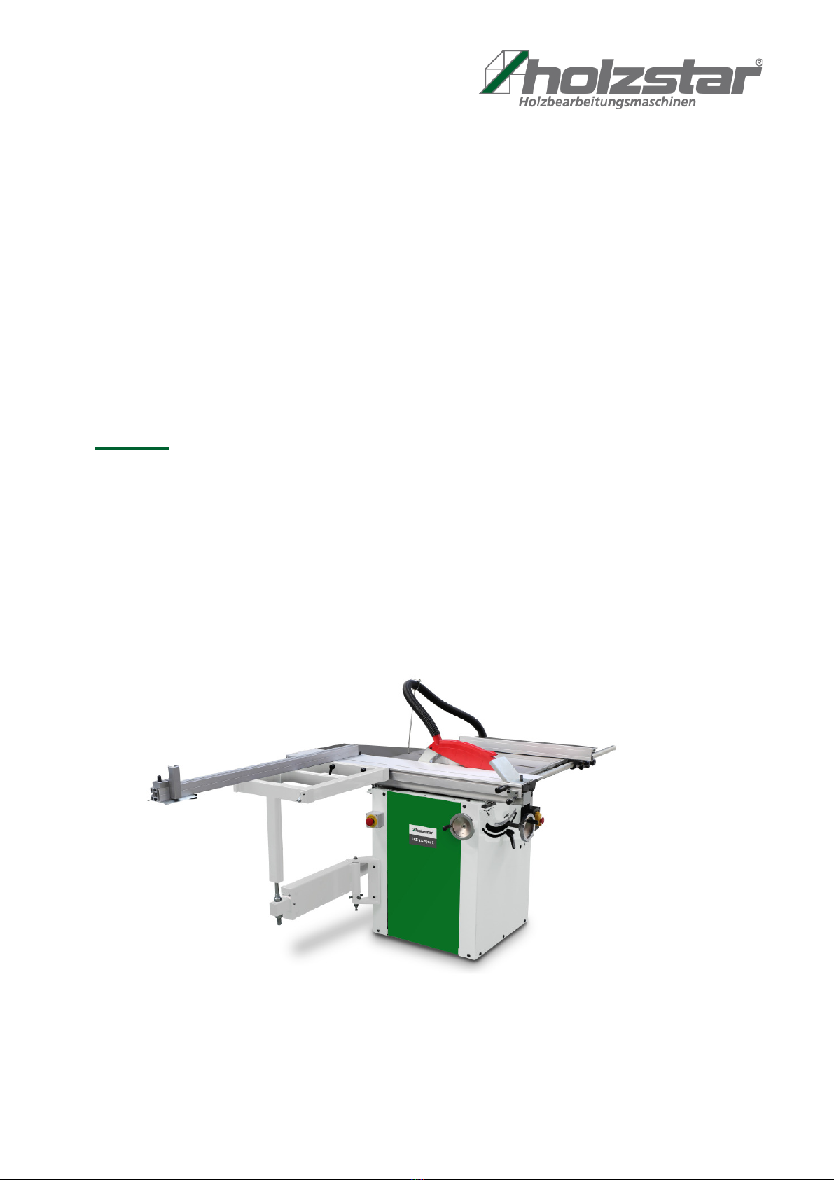
With the purchase of Panel saw from Holzstar you have
made a good choice.
Read the operating instructions carefully before
commissioning.
This informs you about the proper commissioning, the in-
tended use as well as the safe and efficient operation
and maintenance of your Panel saw.
The operating instructions are part of the panel saw. Al-
ways keep this operating manual in the place of use of
your Panel saw. In addition, observe the local accident
prevention regulations and general safety regulations for
the area of application of the Panel saw.
1.1 Copyright
The contents of these operating instructions are pro-
tected by copyright. Their application is permitted within
the context of the use of the panel saw. Any further use
shall not be permitted without written consent by the ma-
nufacturer. For the protection of our products, we shall
register tra-demark, patent and design rights, as this is
possible in individual cases. We strongly oppose any in-
fringement of our intellectual property.
1.2 Customer service
Please contact your specialist retailer if you have any
questions regarding your panel saw or require any tech-
nical information. Your specialist retailer will be happy to
support you with specialist advice and information.
Germany:
Stürmer Maschinen GmbH
r.-Robert-Pfleger-Str. 26
-96103 Hallstadt
Repair-Service:
Fax: 0049(0)951 96555-111
E-Mail: service@stuermer-maschinen.de
Internet: www.holzstar.de
Spare parts ordering:
Fax: 0049(0)951 96555-119
E-Mail: ersatzteile@stuermer-maschinen.de
We are always interested in valuable experience and
knowledge gained from using the application, whichthen
could be shared and be valuable to develop ourproducts
even further.
1.3 Limitation of liablility
All information and instructions has been compiled on
the basis of the state-of-the-art, valid standards and gui-
delines as well as our many years of expertise and expe-
rience.
The manufacturer shall not be liable for damage in the
following cases:
- Non-observance of these operating instructions
- Unintended use
- Deployment of untrained staff
- Conversions at one's own responsibility
- Technical modifications
- Use of unauthorised spare parts
The actual scope of delivery may deviate from the expla-
nations and illustrations described here in the case of
special designs, use of additional order options or due to
the latest technical changes.
The obligations agreed in the delivery contract, the gene-
ral terms and conditions as well as the delivery conditi-
ons of the manufacturer and the legal regulations valid at
the time of the conclusion of the contract apply.
2 Safety
This section provides an overview of all important safety
packages for personal protection as well as safe and re-
liable operation. The sections on individual service life
phases contain additional, specifically applicable safety
information.
2.1 Symbol explanation
Safety Instructions
Safety instructions are indicated by symbols in these ope-
rating instructions. The safety instructions are in-itiated by
signal words that express the extent of the ha-zard.
ANGER!
This combination of symbol and signal term indica-
tes a directly dangerous situation which may
cause death or serious injury if not averted.
WARNING!
This combination of symbol and signal term indica-
tes potentially hazardous situations which may cause
death or serious injury if not averted.

4 FKS 315-1500 E | Version 1.07
Safety
Tips and recommendations
Observe the safety information in these operating in-
structions to minimise the risk of personal injury as well
as material damage and prevent hazardous situations.
2.2 Personal protective equipment
Personal protective equipment is intended to protect the
health and safety of persons at work. Staff must wear the
personal protective equipment indicated in individual
sections of these operating instructions when carrying
out the different tasks on the machine.
The personal protective equipment is described in the
following section:
2.3 Safety labels on the Panel saw
The following safety markings are attached to the panel
saw (Fig. 1), which must be observed and followed.
Fig. 1: Safety signs
If safety labels on the machine are damaged or missing,
this can cause errors, personal injury and material da-
mage. The safety symbols attached to the machine must
not be removed. Damaged safety symbols must be re-
placed immediately.
As soon as the signs are not clearly visible and compre-
hensible at first glance, the machine must be stopped
until new signs have been attached.
CAUTION!
This combination of symbol and signal word indicates
a potentially hazardous situation which, if not avoi-
ded, could result in minor injury..
ATTENTION
This combination of symbol and signal term indica-
tes a potentially hazardous situation which may
cause minor or light injuries if it is not averted.
NOTE!
This combination of symbol and signal term indica-
tes a potentially dangerous situation which may
cause material damage or harm the environment if it
is not averted.
Tips and recommendations
This symbol highlights useful tips and recommendati-
ons as well as information for efficient and reliable
operation.
Hearing- and Head protection
The hearing protection protects the ears against
damages of hearing due to noise. The industrial hel-
met protects the head against falling objects and kno-
cks against stationary objects items.
Eye protection
Protective glasses protect the eyes against projected
parts and splashes of liquid.
Protective gloves
The protective gloves are used to protect the hands
from sharp-edged components, as well as against
friction, abrasions or deeper injuries.
Safety shoes
The safety shoes protect the feet from bruising, falling
parts and slipping on slippery surfaces.
Protective clothing
Protective clothing is tight-fitting work clothing, with no
protruding parts, with low tear resistance.
234
1
6
5

Intended use
FKS 315-1500 E | Version 1.07 5
2.4 Safety equipment
Emergency stop button
The machine FKS 315-1500 E is equipped with an
EMERGENCY STOP button (A, Fig. 3).
Fig. 2: EMERGENCY STOP button and ON / OFF switch
In emergencies, press the EMERGENCY STOP button
and the machine will stop immediately. The power supply
is switched off or the drives are mechanically dis-
connected. After the emergency stop button has been
pressed, it must be unlocked by turning it in the direction
of the arrow so that it can be switched on again.
Motor protection switch
There is a thermal protection switch in the motor of the
Panel saw, which switches off the motor automatically in
case of thermal overload.
After eliminating the cause of the overload and waiting
for the engine to cool down completely, the engine can
be restarted.
Workpiece kickback protection
Fig. 3: Workpiece kickback protection
If necessary, the workpiece kickback guard can be
mounted on the sliding carriage to prevent the workpiece
from being knocked back.
3 Intended use
The Panel saw FKS 315-1500 E is used for sawing with
versatile adjustable angles of boards and strips. The
processing of solid wood, chipboard, panels and profiles
is possible. In compliance with the safety instructions,
the conditions of use for the saw blade used must be ob-
served. Firewood must not be processed. The machine
must be operated with a suitable extraction system. It is
suitable for private use, not for industrial use. Proper use
also includes compliance with all information in this ma-
nual. Any use beyond the intended use or otherwise is
considered misuse.
For structural and technical changes on the panel saw the
company St rmer Maschinen GmbH assumes no liability.
Claims of any kind due to damage due to improper use are
excluded.
WARNING!
Risk of misuse!
Misuse of the panel saw can lead to dangerous situa-
tions.

6 FKS 315-1500 E | Version 1.07
Technical ata
4 Technical Data
4.1 Table
4.2 Type plate
Fig.. 4: Type plate FKS 315-1500 E
5 Transport, Packaging, Storage
5.1 Delivery and transport
elivery
Check the Panel saw for visible transport damage after
delivery. If you discover any damage to Panel saw, im-
mediately report it to the transport company or the de-
aler.
Transport
Transport with a forklift / pallet truck:
For shipping, the boxed unit is delivered on a pallet so
that it can be transported by forklift or pallet truck.
5.2 Packaging
All used packaging materials and packaging aids of the
panel saw are recyclable and must always be recycled.
Packing components made of cardboard are crushed to
waste paper collection.
The foils are made of polyethylene (PE) and the uphol-
stery parts made of polystyrene (PS). You can hand over
these substances to a recycling center or to the disposal
company responsible for you.
5.3 Storage
Thoroughly clean the panel saw in a dry, clean and frost-
free environment. Cover the machine with a protective
tarpaulin.
Ambient temperature range: -25 ° C to +55 ° C.
Model
FKS 315-1500 E
Electrical connection 400 V /
50Hz
3,0 kW
Table dimensions [mm]
350 x 760
Extension table steel [mm]
600 x 760
Rear table [mm]
350 x 500
Sliding table [mm]
1500 x 238
Telescopic stop [mm]
1200-2200
Max. saw blade Ø
Ø 315 mm
Saw blade speed
4250 min-1
Max. cutting height 90°
100 mm
Max. cutting height 45°
75 mm
Max. Trimming length
1370 mm
Max. Max. cutting width with
stop
940 mm
Weight
202 kg
Sound level with no-load
85 dB(A)
Suction for
Blade guard
Machine
Ø 40 mm
Ø 100 mm
Min. Suction speed
20 m/s
Extraction volume
Blade guard
Machine
140 m3/h
690 m3/h
WARNING!
Risk of death!
If the weight of the device and the permissible lifting
capacity of the lifting gear are not observed during
transport or lifting, the device may topple over or fall
over.
- During transport and during lifting work, pay atten-
tion to the weight of the device and the permissible
load capacity of the lifting equipment.
- Check lifting gear and load attachment means for
perfect condition.

escription of the device
FKS 315-1500 E | Version 1.07 7
6 Description of the device
6.1 Machine
Illustrations in this manual may differ from the origi-
nal.
Fig. 5: Panel saw FKS 315-1500 E
1 Extension table
2 Main table
3 Saw blade protection with suction connection
4 Saw blade
5 Rear extension table
6 Sliding carriages
7 Telescopic stop
8 Sliding table
9 Substructure
10 ON and OFF switch
11 EMERGENCY STOP button
12 Workpiece hold-down device
13 Handwheel for adjusting the saw blade height
14 Handwheel for fine adjustment of the inclination angle
15 Stop
16 Drive
6.2 Scope of delivery:
- Sliding carriage with boom
- Bed extension and width extension
- Clamp sleigh
- Rip fence with rod guide and fine adjustment
- Saw blade protective hood with extraction hose
Fig. 6: Tools for FKS 315-1500 E
7 Setting up and connection
7.1 Requirements for the installation site
The panel saw must be set up stable on a level and firm
ground. It is important to ensure that there is enough
freedom of movement to work. The site should meet the
following criteria:
- The substrate must be level, firm and vibration-
free.
- Altitude of the workplace: max. 1000 m;
- Max ambient temperature: 40 ° C
- Min ambient temperature: 5 ° C
- Max humidity at 40 ° C: 50%:
- Max humidity at 20 ° C: 90%
- The substrate must not let any lubricant through.
- The installation or work area must be dry and well
ventilated.
- Do not operate machines that cause dust and
chips near the machine.
- There must be sufficient space for the operating
personnel, for material transport as well as for ad-
justment and maintenance work.
- The site must have good lighting.
- There must be a suction device with min. 690 m3 /h
extraction capacity, min. 20 m / s flow velocity at
the suction connection; Hose diameter 100 mm,
max. Hose length 4 m.
7.2 Setting up the panel saw
CAUTION!
Danger of injury due to a machine that is not stably er-
ected!
Check the stability of the machine after placing it on
stable ground.

8 FKS 315-1500 E | Version 1.07
Setting up and connection
Make the machine operational by following these steps:
Mount sliding carriage and saw blade guard
Fig. 7: Mount sliding carriage and saw blade guard
Step 1: Screw the sliding carriage B to the frame F with
the screws, washers and nuts 8, 9, 10.
Step 2: Screw the handle C with washer and nut 4, 5 to
the sliding carriage. Screw the workpiece hol-
der A to the sliding carriage with the screw,
washer and nuts 1, 2, 3.
Step 3: Screw the saw blade guard E to the cutting knife
D with the screw and nut 6, 7.
Mount sliding table
Fig. 8: Mount sliding table
Step 4: Insert the sliding table B in the sliding carriage A
and the carrier C and fix it to the sliding car-
riage A with the clamping levers 2 and plate 1.
Mount telescopic stop and extension tables
Fig. 9: Mount telescopic stop and extension tables
Step 5: Insert the telescopic stopper A with the bolt in the
hole on the sliding table B and fix it with the
clamping lever 1 after adjusting the angle.
Fig. 10: Mount extension tables
Step 6: Loosely screw the extension tables B and C with
the screws and washers 2, 3. Then align the
extension tables in height on table A and tigh-
ten the screws. Fit hose guide D to table C.
CAUTION!
Some metal parts can be sharp-edged. Check all me-
tal parts to avoid injury.
CAUTION!
Pay attention to the weight of the machine!
The machine may only be set up by two persons.
Check the aid accordingly for sufficient dimensioning
and load capacity.
ATTENTION!
To ensure sufficient stability of the machine, it should
be screwed to the ground. There are 4 holes on the
machine housing for this purpose

Setting up and connection
FKS 315-1500 E | Version 1.07 9
Fig. 11: Mount measuring bar and guide rail
Step 7: Screw the measuring strip B to the table A with
the screws 3. Then screw on the guide rail with
screws and nuts 1, 2.
Mounting the stop
Fig. 12: Mounting the stop
Step 8: Attach the stopper clip B to the guide rail C, then
attach stopper A to B.
Align the tables
Fig. 13: Align the tables
Step 9: Set the distance between A and B to less than 3
mm. Then tighten bolts 1 and 2. Place a guide-
line on the steel table and the sliding table and
adjust the height with the screws 5 and 6, then
tighten the clamping screws 3 and 4.
Fig. 14: Align extension tables
Step 10: Place a guideline (A) on the steel table and ex-
tension tables E and F and adjust the height.
Mount the suction hoses
Fig. 15: Mount the suction hoses
Step 1: Attach the 40 mm suction hose to the saw blade
guard with a hose clamp, then insert the hose
into the hose guide. Make sure that the hose
runs freely and that there is enough clearance
to the work surface.
Step 2: Attach the other end of the suction hose to the
suction connection on the machine housing
with a hose clamp.
Step 3: Attach the 100 mm suction hose to the suction
connection on the machine housing with a
hose clamp. Attach the other end of the suction
hose with a hose clamp to the intake manifold
of the extraction system.

10 FKS 315-1500 E | Version 1.07
Operation of the Panel saw
7.3 Electrical connection
When making electrical connections, make sure that the
characteristics (voltage, mains frequency, protection)
match those on the rating plate and for the motor.
Requirements for the power grid:
- Overvoltage protection and undervoltage protec-
tion
- Voltage deviation from the nominal value: 0.9-1.1
- Frequency deviation from the nominal value: 0.99-
1.01
- Hedging: 16 A
Step 1: Check that the panel saw is switched off.
Step 2: Connect the machine to the mains and check the
direction of motor rotation. If the direction of rota-
tion is wrong, two phases must be exchanged.
8 Operation of the Panel saw
With the sliding table of the sliding table saw large-sized
workpieces can be cut, without the stresses that would
occur through sawing on a stationary table.
In addition, the saw can be used as a regular table saw
to cut smaller workpieces.
ANGER!
To ensure sufficient stability of the machine, it should
be screwed to the ground. There are 4 holes on the
machine housing for this purpose
ANGER!
anger of electrocution!
There is danger to life when in contact with live com-
ponents. Switched on electrical components can
cause uncontrolled movements and lead to serious
injuries.
ATTENTION!
All work on the electrical installation may only be car-
ried out by a qualified electrician.
ANGER!
The three phases must be connected in such a way
that the saw blade moves according to the cutting di-
rection shown on the housing.
ANGER!
anger of electrocution!
There is danger to life when in contact with live com-
ponents. Switched on electrical components can
cause uncontrolled movements and lead to serious
injuries.
- - Disconnect the power before starting adjustments
to the machine.
WARNING!
Risk of death!
There is danger to life for the operator and other per-
sons if they do not adhere to the following rules.
- The panel saw may only be operated by a trained
and experienced person.
- The operator may not work while under the influ-
ence of alcohol, drugs or medication.
- The operator must not work when he is tired or suf-
fering from concentration-impairing illnesses.
- The panel saw may only be operated by one person.
Other persons must keep away from the work area
during operation.
CAUTION!
Crushing!
Incorrect work on the machine can cause injury to the
upper limbs.
Wear ear protection!
Wear safety glasses!
Wear safety shoes!
Wear protective clothing!

Operation of the Panel saw
FKS 315-1500 E | Version 1.07 11
Working position
Fig. 16: Working position
Working positions on the sliding table saw:
A: Working with the sliding table
B: Working on the saw table
Workpiece downholder
Fig. 17: Workpiece downholder
Before the sawing process, place the workpiece hold-
down in a suitable position to the workpiece to prevent
the workpiece from striking back during sawing (kickback
protection).
ON-OFF switch
Fig. 18: ON-OFF switch (B)
To start the machine, press the green START button.
Select suitable saw blade
Fig. 19: Number of teeth of a suitable saw blade: A
For a safe operation:
- Check that the machine is well secured and does
not vibrate.
- Never take the workpiece back after cutting starts.
- Work at the proper and consistent feed rate, never
stopping the workpiece during the cut.
- Only work with a sharp saw blade.
- Select suitable saw blade: At least 2 - 3 teeth
should always cut the workpiece at the same time
(A, Fig. 19).
8.1 Sawing with the sliding table
Fig. 20: Sawing operation with sliding table
Step 1: Place the workpiece on the sliding table and fix it
to stop B and kickback guard C.
Step 2: Turn on the suction device and the saw.
Step 3: From working position A push the sliding carriage
in the direction of the saw blade.

12 FKS 315-1500 E | Version 1.07
Care, Maintenance and Repair
8.2 Sawing with the sliding table
Step 1: Slide the sliding table out of the sawing area and
clamp the sliding carriage in a stationary posi-
tion.
Step 2: Adjust the fence to the desired cutting width.
Step 3: Place the workpiece on the saw table.
Fig. 21: Sawing operation with the saw table
Step 4: Turn on the suction device, turn on the saw, and do
the sawing.
8.3 Height adjustment
Fig. 22: Handwheel for height adjustment of the saw blade
Step 1: Loosen the handwheel clamping lever for adju-
sting the height of the saw blade.
Step 2: Adjust the desired position of the saw blade with
the handwheel and lock the handwheel with
the clamping lever again.
8.4 Adjust inclination angle
Fig. 23: Handwheel for adjusting the angle of inclination (left)
Step 1: Release the handwheel clamping lever to adjust
the saw blade tilt angle (Fig. 23, left).
Step 2: Use the handwheel to set the desired angle of in-
clination of the saw blade using the scale (Fig.
23, right). Then lock the handwheel with the
clamping lever again.
9 Care, Maintenance and Repair
9.1 Care after the end of work
Step 1: Disconnect the power plug from the socket.
Step 2: Empty and clean the suction device.
ANGER!
anger of electrocution!
There is danger to life when in contact with live com-
ponents. Switched on electrical components can
cause uncontrolled movements and lead to serious
injuries..
- Before starting any cleaning or maintenance
work,switch off the machine and disconnect the po-
wer plug.
Wear safety gloves!
NOTE!
Never use harsh cleaning agents for cleaning. This
can lead to damage or destruction of the device.

Care, Maintenance and Repair
FKS 315-1500 E | Version 1.07 13
Fig. 24: Clean the machine
Step 3: Extract the machine from sawdust and sawdust
and clean it with a dry cloth and / or compres-
sed air (wear protective goggles!). In particular,
the guide rails B (Fig. 24) and the sliding carrier
A (Fig. 24) must be kept clean.
Fig. 25: Important lubrication points
Step 4: Lubricate all moving parts, especially A, B (Fig.
25) regularly (weekly). Protect all belts and pul-
leys against oiling!
Step 5: Spray all unpainted metal surfaces with some
anti-rust spray.
Step 6: Inspect the machine for damage to the safety de-
vices and saw blade. If necessary, carry out the
repair or arrange for it, observing the safety in-
structions.
Step 7: Check the machine regularly and replace if
necessary:
- Loose screws and nuts
- Worn or damaged switches
- Worn or damaged saw blade
- Worn or damaged blade guard
Step 7: Every 3 months, check the drive belts monthly for
daily use, replace if worn or damaged.
9.2 Maintenance and Repair
Maintenance and repair work may only be carried out by
qualified personnel.
If the panel saw does not work properly, contact a dealer
or our customer service. The contact details can be
found in chapter 1.2 Customer Service.
All protection and safety equipment must be reinstalled
immediately after completion of repair and maintenance
work.
9.2.1 Change the saw blade
Step 1: Disconnect the power plug from the socket.
Step 2: Adjust the saw blade inclination angle to 0 ° (90 °
to the saw table) and raise the saw blade as far
as possible.
Step 3: Push the sliding carriage to the right as far as
possible, unscrew the two M6x12 screws and re-
move the saw blade guard.
Step 4: Remove the insert at the table.
Step 5: Insert the shaft pin into the hole on the inside of
the saw blade flange to lock the saw blade and
unscrew the saw blade nut clockwise with the
wrench.
NOTE!
The bearings are closed and pre-lubricated. They are
maintenance-free for the normal life of the machine.
The bearing surfaces should always be kept clean to
ensure proper operation of the saw.
Wear safety gloves!
ANGER!
The saw blade measures 315 x 30 x 3 mm (outer dia-
meter, inner diameter, thickness)
ANGER!
Each time you change the blade thickness, you must
fit an appropriately dimensioned cutting blade and a
suitable auxiliary saw blade.

14 FKS 315-1500 E | Version 1.07
Care, Maintenance and Repair
Fig. 26: Unscrew the saw blade
Step 6: Remove the saw blade flange and the saw blade.
Step 7: Place the new saw blade with flange and nut on
the shaft and tighten the nut (counterclockwise).
Step 8: Check that a correctly dimensioned cutting knife
and a suitable auxiliary saw blade are fitted and
aligned with the saw blade.
Step 9: Mount the saw blade guard.
9.2.2 Change of the riving knife
Fig. 27: Adjust the Riving knife
Step 1: Disconnect the power plug from the power outlet.
Step 2: Adjust the saw blade inclination angle to 0 ° (90 °
to the saw table) and raise the saw blade as far
as possible.
Step 3: Push the sliding carriage to the right as far as
possible, unscrew the two M6x12 screws and re-
move the saw blade guard.
Step 4: Loosen the fastening bolt for the separating knife
and remove the cutting knife.
Step 5: Insert the new cutting knife and loosely screw it
on.
Fig. 28: Set the distance of the cutting blade to the saw blade
Step 6: Screw the cutting knife with a distance between 3
mm and 8 mm from the saw blade.
Step 7: Attach the saw blade guard.
9.2.3 Replace the drive belt
Step 1: Disconnect the power plug from the power outlet.
Step 2: Remove the saw blade, s. Section "saw blade
change".
Step 3: Remove the chip container by unscrewing the 3
M8x18 screws.
Fig. 29: Replace the drive belt
Step 4: Unscrew the 4 screws of the left cover and re-
move the cover.
ANGER!
If the saw blade thickness has changed, an appropri-
ately dimensioned cutting knife and a suitable auxili-
ary saw blade must now be mounted.
ANGER!
The riving knife is partially structured. The structured
area must be below the saw table.
The mounting bolt is inserted in a slot so that the
horizontal distance to the saw blade can be varied.
NOTE!
When removing the lower two M8x18 screws, the in-
clination angle is tilted to 30 °, when removing the up-
per M8x18 screw, the inclination angle is tilted to 0 °.

isposal, recycling of old equipment
FKS 315-1500 E | Version 1.07 15
Fig. 30: Loosen the engine screws
Step 5: Screw the 3 fixing screws of the engine approx. 3
mm out of the engine mount, so that the engine
still remains on the mount.
Step 6: With the help of the second person, unscrew the
3 nuts on the engine mount completely and re-
move the engine
Step 7: Remove remnants of a worn drive belt with the
appropriate tool so that the drive belt fits well
into the grooves.
Step 8: Insert the drive belt into the engine mount
Step 9: The engine is put on and pulled in this position so
tight that there is still enough clearance to ad-
just the drive belt clearance.
Step 10: Put on the spacer ring and secure the self-lock-
ing nut with a washer
Step 11: Place a short bolt or similar between the base
frame and the motor mount. By turning the
height adjustment crank, you can vary the
height adjustment guide.
Step 12: First, the spacer sleeve must be inserted in the
right position shown with a bar iron or appropri-
ate tool. Pull the drive belt upwards and insert
the belt pulley and place the drive belt in the
middle
Step 13: Now insert the saw blade spindle with the
feather key into the top of the motor mount.
Lightly tap the spindle into the bearing, tighten
the spindle with the hexagon socket screw,
tighten the threaded pin of the spacer sleeve.
10 Disposal, recycling of old equipment
In your own interests and in the interests of the environ-
ment, please ensure that all components of the machine
are disposed of in the proper and approved way.
10.1 Decommissioning
Disused machines must be decommissioned immedi-
ately to prevent misuse at a later point and putting the
environment or persons at risk.
Step 1: Remove all environmentally hazardous fluids
from the old unit.
Step 2: If necessary, dismantle the machine into mana-
geable and usable assemblies and compo-
nents.
Step 3: Guide the machine components and operating
materials to the appropriate disposal routes.
10.2 Disposal of electrical equipment
Note that electrical equipment contains a variety of recy-
cling-capable materials and also environmentally hazar-
dous components.
Please help to separate these components and dispose
of them responsibly. In case of doubt, contact your local
waste disposal authority. Consult a specialist disposal
agent for recycling if needed.
10.3 Disposing of lubricants
Lubricant manufacturers provide disposal information for
the lubricants used. If necessary, request product-speci-
fic data sheets.

16 FKS 315-1500 E | Version 1.07
Troubleshooting
11 Troubleshooting
Fault Possible cause Solution
Engine does not start No mains voltage Connection cable
defective
Have the power connection checked
by qualified personnel.
Engine is running but the saw blade
is not turning
Drive belt torn Replace the drive belt
Engine is getting hot 1.Engine short circuit
2.Overload of the engine
1. Disconnect the power plug and
have the machine repaired by qua-
lified personnel.
2. Check whether the saw blade is
suitable for the material to be cut.
Check whether the saw blade is
still sufficiently sharp Take a break
from work and let the engine cool
down.
Saw blade speed too low 1.Engine defective
2.too low mains voltage
1.Have the engine checked by quali-
fied personnel.
2.Have the mains voltage checked
by qualified personnel
Saw blade rotates unevenly under
load
Drive belt not sufficiently tensioned Check the belt tension.
Saw blade does not start or stops un-
der load
Drive belt not sufficiently tensioned Check the belt tension.
Saw vibrates, saw blade strikes 1.Saw blade does not match the spe-
cification
2.Saw blade not sufficiently secured
3.Saw blade defective
1.Check on the basis of the specifi-
cations in the technical data
whether the saw blade is suitable
for installation.
2.Tighten the fixing screw.
3.Check the saw blade for mechani-
cal damage and replace it if neces-
sary.
No clean 45 ° or 90 ° cuts 1.Stops not aligned correctly
2.Angle display not set correctly
1.Check the saw blade with stan-
dard angle and align the stops.
2.Check saw blade with standard
angle and adjust angle display.
Workpiece is knocked back by the
saw blade.
1.Stops not aligned correctly
2.Disconnect blade not aligned with
saw blade
3.Defective saw blade
1.Align the stops.
2.Align the cutting blade with the saw
blade.
3.Replace the saw blade.

Spare parts
FKS 315-1500 E | Version 1.07 17
12 Spare parts
12.1 Spare parts orders
The spare parts can be obtained from the dealer or di-
rectly from the manufacturer. The contact details are in
chapter 1.2 Customer Service.
Specify the following key data for inquiries or when orde-
ring spare parts:
- Device type
- Item number
- Position number
- Construction year
- amount
- desired shipping method (post, freight, sea, air, ex-
press)
- delivery address
Spare parts orders without details given above can not
be considered. If the shipping method is missing, ship-
ping will be at the discretion of the supplier.
Information on the device type, article number and year
of manufacture can be found on the type plate, which is
attached to the device.
Example
The Switch of the Panel saw FKS 315-1500 E must be
ordered. The Switch has the position number 13 in the
spare part drawing 1.
- Type of device: Panel saw FKS 315-1500 E
- Item number: 5900315
- Drawing number: 1
- Position number: 13
The order number is: 0-5900315-1-13
The order number consists of the article number, the
item number and a position in front of the article number.
- Place the digit 0 in front of the item No.
- Also place the digit 0 in front of the position No. 1
trough 9.
ANGER!
Risk of injury due to incorrect spare
parts!
The use of incorrect or faulty replacement parts may
cause danger to the operator and cause damage and
malfunction.
- Only use original spare parts from the manufacturer
or replacement parts approved by the manufacturer.
- In case of doubt, always contact the manufacturer.
Tips and recommendations
Using non-approved spare parts voids the manu-
facturer's warranty

18 FKS 315-1500 E | Version 1.07
Spare parts
12.2 Spare parts drawings FKS 315-1500 E
The following spare parts drawing is intended to help identify the necessary spare parts. To order, please send a copy of
the list of spare parts with the marked components to your dealer.
Fig. 31: Spare parts drawing 1 Panel saw FKS 315-1500 E

Spare parts
FKS 315-1500 E | Version 1.07 19
Fig. 32: Spare parts drawing 2 Panel saw FKS 315-1500 E

20 FKS 315-1500 E | Version 1.07
Spare parts
Fig. 33: Spare parts drawing 3 Panel saw FKS 315-1500 E
Table of contents
Other Holzstar Power Tools manuals
Popular Power Tools manuals by other brands

Textron
Textron Greenlee PSTLPRESS-TOOL32kN Operation manual

Cornwell Tools
Cornwell Tools CAT2000MR operating instructions

Weller
Weller WXHAP 200 operating instructions

Matco Tools
Matco Tools MHG751C quick start guide

Haug
Haug 04.7614.000 operating instructions

Synthesizers.com
Synthesizers.com Q141 quick start guide