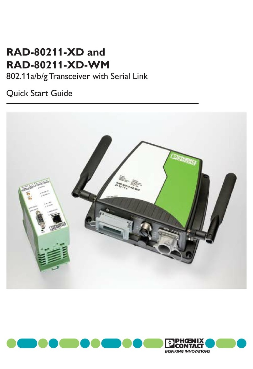
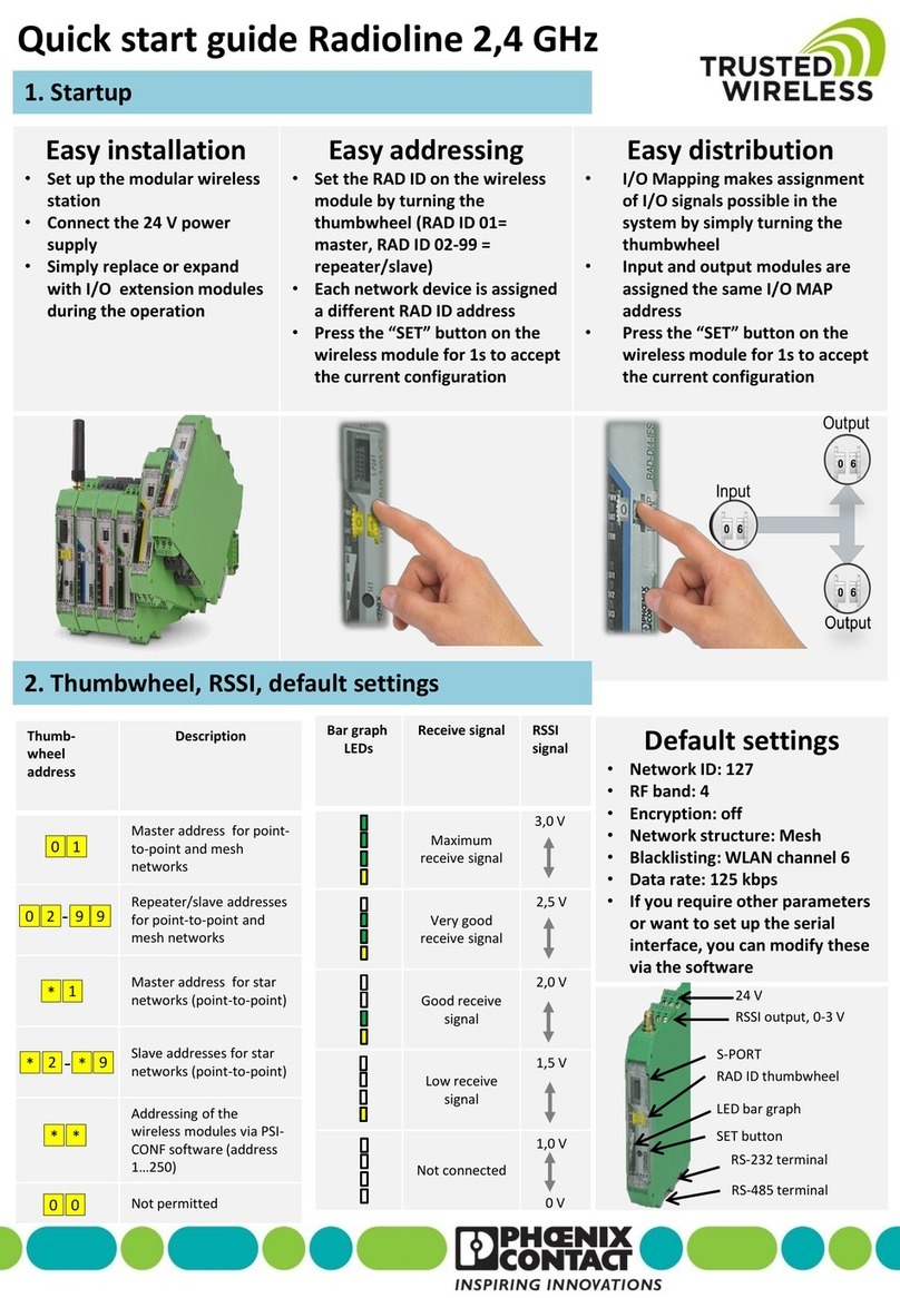
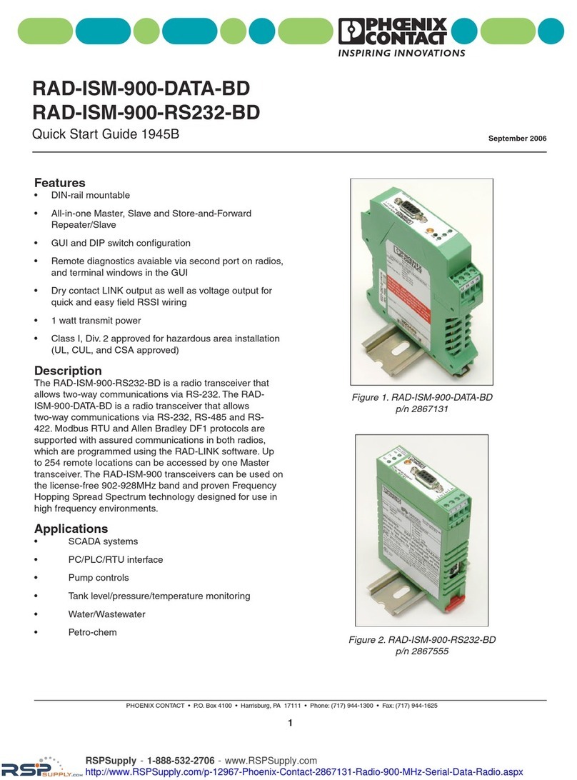
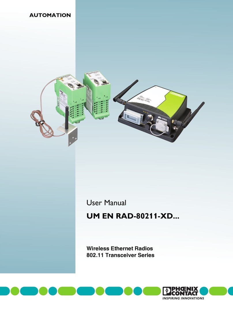
Phoenix Contact RAD IFS Series User manual

User manual
UM EN RAD-...-IFS
Radioline -
Wireless transmission system for
serial interfaces and I/O signals

2018-09-21
PHOENIX CONTACT GmbH & Co. KG • Flachsmarktstraße 8 • 32825 Blomberg • Germany
phoenixcontact.com
105542_en_05
Radioline - Wireless transmission system for serial interfaces and
I/O signals
Designation Order No.
Wireless modules:
RAD-2400-IFS 2901541
RAD-868-IFS 2904909
RAD-2400-IFS-JP 2702863
I/O extension modules:
RAD-AI4-IFS 2901537
RAD-PT100-4-IFS 2904035
RAD-AO4-IFS 2901538
RAD-DI4-IFS 2901535
RAD-DI8-IFS 2901539
RAD-DOR4-IFS 2901536
RAD-DO8-IFS 2902811
RAD-DAIO6-IFS 2901533
User manual
This user manual is valid for:
UM EN RAD-...-IFS, Revision 05

105542_en_05 PHOENIX CONTACT 3 / 198
Table of contents
1 For your safety ...........................................................................................................................7
1.1 Marking of warning notes....................................................................................... 7
1.2 Qualification of users ............................................................................................. 7
1.3 Field of application of the product..........................................................................8
1.4 Installation notes.................................................................................................. 10
1.5 Installation in Zone 2............................................................................................ 11
1.6 Notes for individual I/O extension modules.......................................................... 12
1.7 UL notes (RAD-2400-IFS and I/O extension modules only)................................. 12
1.8 FCC, Industry Canada, IFT Mexico (RAD-2400-IFS only) ................................... 13
2 Brief description .......................................................................................................................15
2.1 Wireless modules ................................................................................................ 15
2.2 Firmware versions ............................................................................................... 16
2.3 I/O extension modules......................................................................................... 17
2.4 Application examples .......................................................................................... 18
3 Installation ................................................................................................................................19
3.1 Wireless module structure...................................................................................19
3.2 Basic circuit diagram ........................................................................................... 20
3.3 Mounting and removal......................................................................................... 20
3.4 Connecting the cables......................................................................................... 22
3.5 Connecting the power supply .............................................................................. 23
3.6 Serial interfaces................................................................................................... 24
3.7 Connecting the antenna ...................................................................................... 27
4 Configuration and startup .........................................................................................................29
4.1 Default settings of the wireless module ............................................................... 29
4.2 Operating mode of the wireless module ..............................................................31
4.3 Setting the address of the wireless module using the thumbwheel......................35
4.4 Configuration using the configuration stick .......................................................... 35
4.5 Copying the device settings via a memory stick .................................................. 37
4.6 Configuration via the PSI-CONF software ...........................................................38
4.7 Diagnostics on the wireless module .................................................................... 44
4.8 Diagnostics via PSI-CONF software....................................................................49
4.9 Starting up I/O extension modules....................................................................... 52
4.10 Startup time of the wireless station ......................................................................54
5 Serial data mode ......................................................................................................................55
5.1 Frame-based data transmission .......................................................................... 57

RAD-...-IFS
4 / 198 PHOENIX CONTACT 105542_en_05
5.2 Setting telegram pauses based on the example of Modbus/RTU........................ 58
6 PLC / Modbus/RTU ..................................................................................................................59
6.1 PLC / Modbus/RTU mode ...................................................................................59
6.2 PLC / Modbus/RTU dual mode............................................................................ 62
6.3 Watchdog............................................................................................................ 65
6.4 Modbus function codes ....................................................................................... 66
6.5 Module type and error code registers for I/O extension modules......................... 67
6.6 Modbus memory map..........................................................................................68
6.7 Error codes and formats for analog input and output values................................ 83
6.8 Radioline function blocks..................................................................................... 84
7 Description of I/O extension modules ......................................................................................87
7.1 RAD-AI4-IFS - analog extension module with four inputs .................................... 87
7.2 RAD-PT100-4-IFS - extension module with four temperature inputs ................... 91
7.3 RAD-AO4-IFS - analog extension module with four outputs ................................ 98
7.4 RAD-DI4-IFS - digital extension module with four inputs ................................... 102
7.5 RAD-DI8-IFS - digital extension module with eight inputs.................................. 106
7.6 RAD-DOR4-IFS - digital extension module with four outputs............................. 111
7.7 RAD-DO8-IFS - digital extension module with eight outputs.............................. 115
7.8 RAD-DAIO6-IFS - analog/digital extension module with six channels ............... 120
8 Planning wireless systems .....................................................................................................125
8.1 Delay time ......................................................................................................... 125
8.2 Pulse transmission ............................................................................................ 127
8.3 Trusted Wireless 2.0.......................................................................................... 127
8.4 RF bands........................................................................................................... 131
8.5 Planning wireless paths..................................................................................... 132
8.6 Practical test...................................................................................................... 132
8.7 Selecting antenna cables and antennas............................................................ 133
8.8 Installing antennas............................................................................................. 134
8.9 Level and attenuation of wireless modules and accessories ............................. 137
8.10 Free space attenuation...................................................................................... 139
8.11 Propagation of radio waves ............................................................................... 141
8.12 Fresnel zone...................................................................................................... 144
8.13 Range................................................................................................................ 146
8.14 Equivalent isotropically radiated power (EIRP).................................................. 147
8.15 System calculation in free space ....................................................................... 148

Table of contents
105542_en_05 PHOENIX CONTACT 5 / 198
8.16 Practical examples ............................................................................................ 149
9 Detecting and removing errors ...............................................................................................151
9.1 Loopback test during serial data transmission................................................... 157
10 Technical data for the wireless modules ................................................................................159
A Technical appendix.................................................................................................................171
A 1 Typical combinations of antennas and adapter cables ......................................171
A 2 Control box for wireless systems ....................................................................... 184
B Appendixes.............................................................................................................................185
B 1 List of figures ..................................................................................................... 185
B 2 List of tables ......................................................................................................189
B 3 Index.................................................................................................................. 191

For your safety
105542_en_05 PHOENIX CONTACT 7 / 198
1Foryoursafety
Read this user manual carefully and keep it for future reference. The screenshots shown in
this user manual may differ from your software version.
1.1 Marking of warning notes
1.2 Qualification of users
The use of products described in this manual is oriented exclusively to electrically skilled
persons or persons instructed by them. The users must be familiar with the relevant safety
concepts of automation technology as well as applicable standards and other regulations.
This symbol indicates hazards that could lead to personal injury.
There are three signal words indicating the severity of a potential injury.
DANGER
Indicates a hazard with a high risk level. If this hazardous situation is not
avoided, it will result in death or serious injury.
WARNING
Indicates a hazard with a medium risk level. If this hazardous situation is not
avoided, it could result in death or serious injury.
CAUTION
Indicates a hazard with a low risk level. If this hazardous situation is not avoided,
it could result in minor or moderate injury.
This symbol together with the NOTE signal word warns the reader of actions
that might cause property damage or a malfunction.
Here you will find additional information or detailed sources of information.

RAD-...-IFS
8 / 198 PHOENIX CONTACT 105542_en_05
1.3 Field of application of the product
1.3.1 Intended use
The devices are designed for use in industrial environments.
The Radioline wireless system is a Class A item of equipment and may cause radio interfer-
ence in residential areas. In this case, the operator may be required to implement appropri-
ate measures and to pay the costs incurred as a result.
Operation of the wireless system is only permitted if accessories available from
Phoenix Contact are used. The use of other accessory components could invalidate the op-
erating license. You can find the approved accessories for this wireless system listed with
the product at phoenixcontact.net/products.
1.3.2 RAD-2400-IFS wireless module
Please note that, in combination with antennas, the maximum permissible transmission
power may be exceeded. In this case, set the transmission power via the software (see
“Transmission power” on page 39).
Install the wireless module at least 1 m away from other devices using the 2.4 GHz fre-
quency band (e.g., WLAN, Bluetooth, microwave ovens). Otherwise, both the link quality
and the data transmission speed will be reduced.
1.3.3 RAD-868-IFS wireless module
For the country registrations, please visit phoenixcontact.net/product/2901541.
The RAD-868-IFS wireless module is only approved for use in Europe and South Africa.

For your safety
105542_en_05 PHOENIX CONTACT 9 / 198
1.3.4 RAD-2400-IFS-JP wireless module
Install the wireless module at least 1 m away from other devices using the 2.4 GHz fre-
quency band (e.g., WLAN, Bluetooth, microwave ovens). Otherwise, both the link quality
and the data transmission speed will be reduced.
1.3.5 Product changes
Modifications to hardware and firmware of the device are not permitted.
Incorrect operation or modifications to the device can endanger your safety or damage the
device. Do not repair the device yourself. If the device is defective, please contact
Phoenix Contact.
The RAD-2400-IFS-JP wireless module is only approved for use in Japan.
The RAD-2400-IFS-JP wireless module does not have ATEX approval. It is not suitable
for use in potentially explosive areas. Only install the wireless module in the safe area.
Japanese Radio Law and Japanese Telecommunications Business Law Compliance
The device is granted pursuant to the Japanese Radio Law ( ) and the
Japanese Telecommunications Business Law ( ).
This device should not be modified (otherwise the granted designation number will
become invalid.

RAD-...-IFS
10 / 198 PHOENIX CONTACT 105542_en_05
1.4 Installation notes
• RAD-2400-IFS and RAD-868-IFS only: Phoenix Contact hereby declares that this
wireless system complies with the basic requirements and other relevant regulations
specified in Directive 2014/53/EC.
• RAD-2400-IFS and RAD-868-IFS only: The category 3 device is suitable for installa-
tion in Zone 2 potentially explosive areas. It meets the requirements of EN 60079-
0:2012+A11:2013 and EN 60079-15:2010.
•Installation, operation, and maintenance may only be carried out by qualified electri-
cians. Follow the installation instructions as described.
•When installing and operating the device, the applicable regulations and safety direc-
tives (including national safety directives), as well as general regulations applicable to
the technology, must be observed. The technical data is provided in the packing slip
and on the certificates (conformity assessment, additional approvals where applica-
ble).
•Do not open or modify the device. Do not repair the device yourself; replace it with an
equivalent device instead. Repairs may only be carried out by the manufacturer. The
manufacturer is not liable for damage resulting from noncompliance.
•The IP20 degree of protection (IEC 60529/EN 60529) of the device is intended for use
in a clean and dry environment. Do not subject the device to mechanical and/or thermal
loads that exceed the specified limits.
•To protect the device against mechanical or electrical damage, install it in suitable
housing with an appropriate degree of protection according to IEC 60529.
•The device complies with the EMC regulations for industrial areas (EMC class A).
When used in residential areas, the device may cause radio interference.
•Only specified devices from Phoenix Contact may be connected to the 12-pos.
S-PORT interface.
•This device is not designed for use in atmospheres with a risk of dust explosions.
•If dust is present, the device must be installed in suitable approved housing, taking the
surface temperature of the housing into consideration.
WARNING: Risk of electric shock
During operation, certain parts of the devices may carry hazardous voltages. Disregarding this warning may
result in serious personal injury and/or damage to equipment.
– Provide a switch/circuit breaker close to the device, which is labeled as the disconnect device for this de-
vice or the entire control cabinet.
– Provide overcurrent protection (I ≤6 A) in the installation.
– Disconnect the device from all power sources during maintenance work and configuration (for SELV or
PELV circuits the device can remain connected).
– The housing of the device provides basic insulation against the neighboring devices for 300 Vrms. If sev-
eral devices are installed next to each other, this must be taken into consideration and additional insulation
may have to be installed. If the neighboring device is equipped with basic insulation, no additional insula-
tion is required.

For your safety
105542_en_05 PHOENIX CONTACT 11 / 198
1.5 Installation in Zone 2
•Observe the specified conditions for use in potentially explosive areas! Install the de-
vice in suitable approved housing (with at least IP54 degree of protection) that meets
the requirements of EN 60079-15. Also observe the requirements of EN 60079-14.
•Only connect devices to the supply and signal circuits in Zone 2 that are suitable for op-
eration in Ex Zone 2 and for the conditions at the installation location.
•In potentially explosive areas, only snap the device on or off the DIN rail connector and
connect/disconnect cables when the power is disconnected.
•The switches of the device that can be accessed may only be actuated when the power
supply to the device is disconnected.
•The device has to be stopped and immediately removed from the Ex area if it is dam-
aged, was subjected to an impermissible load, stored incorrectly, or if it malfunctions.
•Ensure that the radiated wireless power is neither bundled (focused) by the antenna it-
self nor by any inserts in the environment of the antenna, and that it cannot enter neigh-
boring Zones 1 or 0. Please refer to the technical data for the transmission power.
•The HF cable to the antenna must be suitable for the ambient conditions. Install the ca-
ble so that it is protected against mechanical damage, corrosion, chemical stress, and
negative effects from heat or UV radiation. The same applies to the antenna which is
connected to the cable and which functions as a cable termination.
•The antenna must meet the requirements of EN 60079-0 with regard to housing and
electrostatic charge. Otherwise install the antenna in housing that meets the require-
ments of EN 60079-0 and EN 60079-15 and has at least IP54 degree of protection
(EN 60529).
Notes for antennas
•Only use antennas approved for the Ex area (see Section “Accessories” on page 159).
•The intrinsically safe antennas support universal communication in various HF areas.
The antennas are intended for use in potentially explosive areas that require
1G equipment. Connection is via antenna barriers (Order No. 2702198) with separate
approval as intrinsically safe equipment.
•Observe the safety notes in the documentation for the respective antenna.
WARNING: Explosion hazard when used in potentially explosive areas
Make sure that the following notes and instructions are observed.
The RAD-2400-IFS-JP wireless module does not have ATEX approval. It is not suitable
for use in potentially explosive areas. Only install this wireless module in the safe area.

RAD-...-IFS
12 / 198 PHOENIX CONTACT 105542_en_05
1.6 Notes for individual I/O extension modules
For RAD-DI4-IFS, RAD-DOR4-IFS, RAD-DAIO6-IFS
For RAD-AO4-IFS
1.7 UL notes (RAD-2400-IFS and I/O extension
modules only)
For RAD-2400-IFS wireless module
For the I/O extension modules
WARNING: Risk of electric shock
Use the same phase for digital inputs and outputs. The isolating voltage between the in-
dividual channels must not exceed 300 V.
Use either the current or voltage output at every analog channel.
INDUSTRIAL CONTROL EQUIPMENT FOR HAZARDOUS LOCATIONS 45FP
A This equipment is suitable for use in ClassI, Zone2, IIC T4 and ClassI, Division2,
Groups A, B, C, D T4A hazardous locations or non-hazardous locations only.
B WARNING - EXPLOSION HAZARD - DO NOT DISCONNECT EQUIPMENT UN-
LESS POWER HAS BEEN SWITCHED OFF OR THE AREA IS KNOWN TO BE
NON-HAZARDOUS.
C WARNING - EXPLOSION HAZARD - SUBSTITUTION OF COMPONENTS MAY
IMPAIR SUITABILITY FOR CLASS 1, DIVISION 2.
D These devices are open-type devices that are to be installed in an enclosure suit-
able for the environment that is only accessible with the use of a tool.
E WARNING - Exposure to some chemicals may degrade the sealing properties of
materials used in relays within this device.
F WARNING - EXPLOSION HAZARD - S-PORT IS FOR MAINTENANCE AND
PROGRAMMING ONLY AND SHOULD ONLY BE USED WHEN THE AREA IS
KNOWN TO BE NON-HAZARDOUS.
INDUSTRIAL CONTROL EQUIPMENT FOR HAZARDOUS LOCATIONS 45FP
A This equipment is suitable for use in ClassI, Zone2, IIC T4 and ClassI, Division2,
Groups A, B, C, D T4A hazardous locations or non-hazardous locations only.
B WARNING - EXPLOSION HAZARD - DO NOT DISCONNECT EQUIPMENT UN-
LESS POWER HAS BEEN SWITCHED OFF OR THE AREA IS KNOWN TO BE
NON-HAZARDOUS.
C WARNING - EXPLOSION HAZARD - SUBSTITUTION OF COMPONENTS MAY IM-
PAIR SUITABILITY FOR CLASS 1, DIVISION 2.
D These devices are open-type devices that are to be installed in an enclosure suitable
for the environment that is only accessible with the use of a tool.
E WARNING - Exposure to some chemicals may degrade the sealing properties of ma-
terials used in relays within this device.

For your safety
105542_en_05 PHOENIX CONTACT 13 / 198
1.8 FCC, Industry Canada, IFT Mexico (RAD-2400-IFS
only)
FCC
This device complies with Part 15 of the FCC rules. Operation is subject to the following two
conditions:
This device may not cause harmful interference. This device must accept any interference
received, including interference that may cause undesired operation.
Any changes or modifications not explicitly approved by PhoenixContact could cause the
device to cease to comply with FCC rules Part 15, and thus void the user's authority to ope-
rate the equipment.
Radio frequency exposure:
The device contains a radio transmitter and receiver. During communication the device re-
ceives and transmits radio frequency (RF) electromagnetic fields (microwaves) in the fre-
quency range of 2400 MHz to 2483.5 MHz.
RF Exposure Statement:
This equipment should be installed and operated with a minimum distance of 20 cm be-
tween the radiator and your body.
This transmitter must not be co-located or operating in conjunction with any other antenna
or transmitter.
This device contains:
FCC ID: YG3RAD2400A
Industry Canada (IC)
Operation is subject to the following two conditions: (1) this device may not cause interfer-
ence, and (2) this device must accept any interference, including interference that may
cause undesired operation of the device.
This device has been designed to operate with an antenna having a maximum gain of 9 dBi.
Having a higher gain is strictly prohibited per regulations of Industry Canada. The required
antenna impedance is 50 ohms.
To reduce potential radio interference to other users, the antenna type and its gain should
be so chosen that the equivalent isotropically radiated power (EIRP) is not more than that
permitted for successful communication.
This device contains:
IC certificate: 4720B-RAD2400A
NOTE: Interference
This equipment has been tested and found to comply with the limits for a
Class A digital device, pursuant to part 15 of the FCC rules. These limits are
designed to provide reasonable protection against harmful interference when
the equipment is operated in a commercial environment. This equipment
generates, uses and can radiate radio frequency energy and, if not installed
and used in accordance with the instruction manual, may cause harmful inter-
ference to radio communications. Operation of this equipment in a residential
area is likely to cause harmful interference, in which case, the user will be re-
quired to correct the interference at his own expense.

RAD-...-IFS
14 / 198 PHOENIX CONTACT 105542_en_05
IFT, Instituto Federal de Telecomunicaciones México
The operation of this equipment is subject to the following two conditions: (1) it is possible
that this equipment or device may not cause harmful interference, and (2) this equipment or
device must accept any interference including interference that may cause its undesired
operation.
This equipment has been designed to operate with antennas listed below and for an
antenna´s maximum gain of 19dBi. Use of this equipment with antennas not included in this
list or having a higher gain than 19dBi is prohibited. The required antenna impedance is
50ohms.
Certificate number: IFTRCPPHRA17-1112
– Antennas: see table “2.4 GHz antennas”

Brief description
105542_en_05 PHOENIX CONTACT 15 / 198
2 Brief description
Wireless communication is based on Trusted Wireless 2.0 technology. The wireless mod-
ules meet the high requirements for interference-free data transmission through, among
other things, the use of the frequency-hopping spread spectrum (FHSS) method and
128-bit data encryption (AES).
2.1 Wireless modules
In addition to an RS-232 and RS-485 2-wire interface, the wireless modules support the op-
tion of directly connecting up to 32 I/O extension modules in the station structure via the DIN
rail connector.
Addressing of the wireless modules and I/O mapping of the extension modules is carried
out quickly and easily by means of the thumbwheel on the front. The yellow thumbwheel on
the wireless module is used to set the RAD ID. The white thumbwheel on the extension
modules is used to set the I/O MAP address. Programming knowledge is not required. You
can easily start up the wireless network without the need for software.
In addition, the wireless network can be extended with up to 98 RS-485 stations
(RAD-RS485-IFS, Order No. 2702184). I/O data can therefore be distributed across vari-
ous media using the thumbwheel.
The PSI-CONF configuration and diagnostic software for special functions and diagnostic
options of the wireless module is available free of charge.
Features
– Flexible network applications:
I/O data, serial data, PLC / Modbus/RTU mode, dual mode
– Adjustable data rates for the wireless interface
– Easy point-to-point or network structures (star, mesh)
– Yellow thumbwheel for unique addressing of wireless modules in the wireless network
– Integrated RS-232 and RS-485 interfaces
– Can be extended with up to 32 I/O modules per station via DIN rail connector (hot-swap
capability)
– 128-bit AES data encryption and authentication
– Unique network addressing via plug-in configuration stick (RAD-CONF) for secure, par-
allel operation of multiple networks with different RF bands
– Data rates and ranges can be configured using the PSI-CONF software
– International approvals
– Installation in Ex Zone 2 (RAD-2400-IFS and RAD-868-IFS only)
–Canbecombinedwith RS-485 stations
Wireless modules Frequency band
RAD-2400-IFS, RAD-2400-IFS-JP License-free 2.4 GHz ISM band
RAD-868-IFS 868 MHz ISM band, license-free in Europe
The RAD-RS485-IFS RS-485 front module is not described in this user manual.
For additional information, visit phoenixcontact.com/product/2702184.

RAD-...-IFS
16 / 198 PHOENIX CONTACT 105542_en_05
2.2 Firmware versions
Make sure that all the wireless modules in a network have the same firmware version.
Where possible, always use the latest firmware.
You can download the latest firmware free of charge at phoenixcontact.net/products.
Table 2-1 Firmware versions
Function As of firmware version...
RAD-2400-IFS RAD-868-IFS
Initial version 1.00 1.00
PLC / Modbus/RTU mode 1.30 1.00
Support for RAD-DI8-IFS and
RAD-DO8-IFS I/O extension modules
1.40 1.00
Support for RAD-PT100-4-IFS 1.50 1.00
Support for ETSI EN 300328: V1.8.1 1.60 -
Support for RAD-RS485-IFS
RS-485 front module
1.70 1.70
PLC / Modbus/RTU dual mode 1.80 1.80

Brief description
105542_en_05 PHOENIX CONTACT 17 / 198
2.3 I/O extension modules
Various I/O extension modules are available for setting up the wireless system quickly and
easily. You can therefore adapt the number and type of signals to the respective application.
Features
– White thumbwheel for easy and tool-free assignment of device pairs (I/O mapping)
– Modular structure via DIN rail connector (hot-swap capability)
– Depending on the module: channel-to-channel electrical isolation
– Depending on the module: analog inputs or outputs (0/4 mA ... 20 mA / 16-bit resolution
/ <0.1% accuracy)
– Depending on the module: digital wide-range inputs or outputs (0 V ... 250 V AC/DC)
– DIP switches for HOLD/RESET behavior of outputs
– Loop power function for passive sensors
For a detailed description of the available I/O extension modules, refer to the pages listed
below:
Table 2-2 Overview of I/O extension modules
Module type Designation Order
No.
From
page
Analog 4 analog inputs RAD-AI4-IFS 2901537 87
4 Pt 100 inputs RAD-PT100-4-IFS 2904035 91
4 analog outputs RAD-AO4-IFS 2901538 98
Digital 4 digital inputs RAD-DI4-IFS 2901535 102
8 digital inputs or 2 pulse inputs RAD-DI8-IFS 2901539 106
4 digital relay outputs RAD-DOR4-IFS 2901536 111
8 digital transistor outputs RAD-DO8-IFS 2902811 106
Analog/
digital
1 analog input/output, 2 digital
wide-range inputs/outputs RAD-DAIO6-IFS 2901533 121

Installation
105542_en_05 PHOENIX CONTACT 19 / 198
3 Installation
3.1 Wireless module structure
Figure 3-1 Wireless module structure
Item Te r m i n a l
block
Designation
1 RSMA antenna connection (socket)
2 2.1/2.2 RSSI test output (0 V ... 3 V DC) for evaluation of the wireless signal
strength
3 1.1/1.2 Device supply (+24 V DC, GND)
4 S-PORT (12-pos. programming interface)
5 Yellow thumbwheel for setting the RAD ID
6SETbutton
7 Connection option for DIN rail connector
8DINrail
9 Metal foot catch for DIN rail fixing
10 4.1/4.2 Connection terminal blocks for RS-485 interface
11 5.1/5.2/5.3 Connection terminal blocks for RS-232 interface
12 6.1/6.2/6.3 Relay output with floating changeover contact (RF link relay)
13 Status LED (RX/TX) for RS-232/485 serial interface
14 LED bar graph for displaying the wireless signal strength
15 ERR status LED, red (communication error)
16 DAT status LED, green (bus communication)
17 PWR status LED, green (supply voltage)
+24V
RSSI+RSSI-
ANT
COM
1
NO
1
NC
1
RXTXGND
D(A)D(B)
Reset
RAD-ID RAD-2400-IFS
S.PORT
8
8
PWR
DAT
ERR
RXTX
0V
+24V0V
RSSI+RSSI-
2
1
3
4
5
7
6
9
11
12
17
16
13
15
14
10
8

RAD-...-IFS
20 / 198 PHOENIX CONTACT 105542_en_05
3.2 Basic circuit diagram
Figure 3-2 Basic circuit diagram for the wireless module
3.3 Mounting and removal
You can connect up to 32 different I/O extension modules to each wireless module via the
DIN rail connector. Data is transmitted and power is supplied to the I/O extension modules
via the bus foot.
When using the device in a connection station, use the supplied 17.5 mm DIN rail connec-
tor. Only use the DIN rail connector in conjunction with 24 V DC devices.
Figure 3-3 Radioline connection station with up to 32 I/O extension modules
– Mount the wireless module to the left and the I/O extension modules only to the right
of the wireless module.
– The individual extension modules can be arranged in any order.
–2.4 GHz wireless modules only: install the wireless module at least 1 m away from
other devices using the 2.4 GHz frequency band (e.g., WLAN, Bluetooth, microwave
ovens). Otherwise, both the link quality and the data transmission speed will be re-
duced.
RF
5.1
5.2
5.3
RX
TX
RS232
GND
4.1
4.2
D(A)
D(B)
RS485
RAD-ID
S-Port
1.2
1.1 +24 V
0 V
2.1
2.2
RSSI+
RSSI-
U
IFS
IFS
µC
6.1
6.2
6.3
NC
1
NO
1
COM
1
DC
DC
This manual suits for next models
22
Table of contents
Other Phoenix Contact Transceiver manuals

Phoenix Contact
Phoenix Contact RAD-80211-XD User manual

Phoenix Contact
Phoenix Contact RAD-ISM-900-DATA-BD User manual

Phoenix Contact
Phoenix Contact RAD-80211-XD User manual

Phoenix Contact
Phoenix Contact RAD-900-IFS User manual

Phoenix Contact
Phoenix Contact RAD-900-IFS User manual

Phoenix Contact
Phoenix Contact RAD-80211-XD User manual

Phoenix Contact
Phoenix Contact RAD-2400-IFS User manual

Phoenix Contact
Phoenix Contact RAD-80211-XD User manual