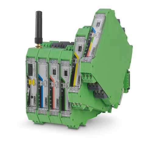
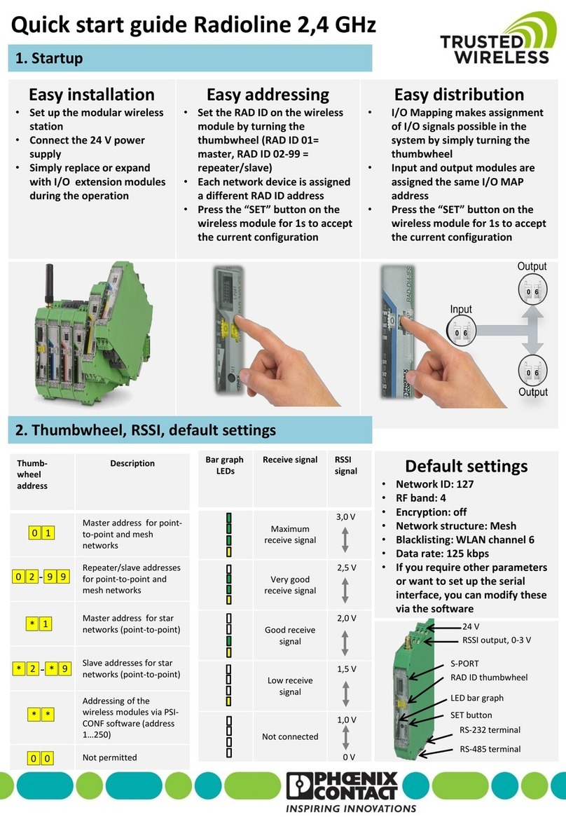
Phoenix Contact RAD-80211-XD User manual

AUTOMATION
User Manual
Wireless Ethernet Radios
802.11 Transceiver Series
UM EN RAD-80211-XD...


Designation:
Revision:
Order No.:
This user manual is valid for:
AUTOMATION
2186_en_I PHOENIX CONTACT
04/2009
Wireless Ethernet Radios 802.11 Transceiver Series
UM EN RAD-80211-XD...
I
Designation Version Order No.
RAD-80211-XD 2885728
RAD-80211-XD-BUS 2885757
RAD-80211-XD-WM 2885715
User Manual

RAD-80211-XD...
PHOENIX CONTACT 2186_en_I
Please observe the following notes
In order to ensure the safe use of the product described, you have to read and understand
this manual. The following notes provide information on how to use this manual.
User group of this manual
The use of products described in this manual is oriented exclusively to
Phoenix Contact accepts no liability for erroneous handling or damage to products from
Phoenix Contact or third-party products resulting from disregard of information contained in
this manual.
Explanation of symbols used and signal words
The following types of messages provide information about possible property damage and
general information concerning proper operation and ease-of-use.
This is the safety alert symbol. It is used to alert you to potential personal injury
hazards. Obey all safety messages that follow this symbol to avoid possible
injury or death.
DANGER
This indicates a hazardous situation which, if not avoided, will result in death or serious
injury.
WARNING
This indicates a hazardous situation which, if not avoided, could result in death or serious
injury.
CAUTION
This indicates a hazardous situation which, if not avoided, could result in minor or
moderate injury.
NOTE
This symbol and the accompanying text alerts the reader to a situation which may cause
damage or malfunction to the device, either hardware or software, or surrounding
property.
This symbol and the accompanying text provides additional information to the reader. It is
also used as a reference to other sources of information (manuals, data sheets, literature)
on the subject matter, product, etc.

RAD-80211-XD...
2186_en_I PHOENIX CONTACT
General terms and conditions of use for technical documentation
Phoenix Contact reserves the right to alter, correct, and/or improve the technical
documentation and the products described in the technical documentation at its own
discretion and without giving prior notice, insofar as this is reasonable for the user. The
same applies to any technical changes that serve the purpose of technical progress.
The receipt of technical documentation (in particular data sheets, installation instructions,
manuals, etc.) does not constitute any further duty on the part of Phoenix Contact to furnish
information on alterations to products and/or technical documentation. Any other
agreement shall only apply if expressly confirmed in writing by Phoenix Contact. Please
note that the supplied documentation is product-specific documentation only and that you
are responsible for checking the suitability and intended use of the products in your specific
application, in particular with regard to observing the applicable standards and regulations.
Although Phoenix Contact makes every effort to ensure that the information content is
accurate, up-to-date, and state-of-the-art, technical inaccuracies and/or printing errors in
the information cannot be ruled out. Phoenix Contact does not offer any guarantees as to
the reliability, accuracy or completeness of the information. All information made available
in the technical data is supplied without any accompanying guarantee, whether expressly
mentioned, implied or tacitly assumed. This information does not include any guarantees
regarding quality, does not describe any fair marketable quality, and does not make any
claims as to quality guarantees or guarantees regarding the suitability for a special purpose.
Phoenix Contact accepts no liability or responsibility for errors or omissions in the content
of the technical documentation (in particular data sheets, installation instructions, manuals,
etc.).
The aforementioned limitations of liability and exemptions from liability do not apply, in so
far as liability must be assumed, e.g., according to product liability law, in cases of
premeditation, gross negligence, on account of loss of life, physical injury or damage to
health or on account of the violation of important contractual obligations. Claims for
damages for the violation of important contractual obligations are, however, limited to
contract-typical, predictable damages, provided there is no premeditation or gross
negligence, or that liability is assumed on account of loss of life, physical injury or damage
to health. This ruling does not imply a change in the burden of proof to the detriment of the
user.
RAD-80211-XD...
PHOENIX CONTACT 2186_en_I
Statement of legal authority
This manual, including all illustrations contained herein, is copyright protected. Use of this
manual by any third party is forbidden. Reproduction, translation, and public disclosure, as
well as electronic and photographic archiving or alteration requires the express written
consent of Phoenix Contact. Violators are liable for damages.
Phoenix Contact reserves all rights in the case of patent award or listing of a registered
design. Third-party products are always named without reference to patent rights. The
existence of such rights shall not be excluded.
Modbus is a registered trademark of Schneider Automation. Wi-Fi is a registered trademark
of the Wi-Fi Alliance.
How to contact us
Internet Up-to-date information on Phoenix Contact products and our Terms and Conditions can be
found on the Internet at:
www.phoenixcontact.com.
Make sure you always use the latest documentation. It can be downloaded at:
www.phoenixcontact.net/download.
Subsidiaries If there are any problems that cannot be solved using the documentation, please contact
your Phoenix Contact subsidiary. Subsidiary contact information is available at
www.phoenixcontact.com.
Published by .
Should you have any suggestions or recommendations for improvement of the contents and
layout of our manuals, please send your comments to
PHOENIX CONTACT GmbH & Co. KG
Flachsmarktstraße 8
32825 Blomberg
Germany
Phone +49 - (0) 52 35 - 3-00
Fax +49 - (0) 52 35 - 3-4 12 00

2186_en_I PHOENIX CONTACT i
Table of Contents
1 802.11 Series Overview...........................................................................................................1-3
1.1 Basic Features of the IEEE 802.11 Wireless Standards .....................................1-3
1.2 Radio Descriptions .............................................................................................1-4
1.3 Wireless Standard IEEE 802.11 Basics..............................................................1-8
1.4 Access Point/Client Configurations ....................................................................1-9
1.5 Bridge Configurations.........................................................................................1-9
1.6 Data Encryption and Security ...........................................................................1-11
1.7 SSID (Service Set ID) .......................................................................................1-11
1.8 Access Point and Client Encryption..................................................................1-12
1.9 Bridge Encryption .............................................................................................1-13
1.10 DHCP Server....................................................................................................1-13
1.11 Operator Authentication and Management.......................................................1-14
1.12 Modbus/TCP I/O Emulation..............................................................................1-14
1.13 Ethernet Terminal Server..................................................................................1-14
2 System Planning......................................................................................................................2-3
2.1 Accessing the Site..............................................................................................2-3
2.2 Path Quality Analysis..........................................................................................2-3
2.3 Signal Strength ................................................................................................... 2-3
2.4 Antennas and Cabling ........................................................................................2-4
2.5 Antenna Mounting Considerations .....................................................................2-6
2.6 Maintaining System Performance.......................................................................2-7
3 Installation ...............................................................................................................................3-3
3.1 Mounting the Radios...........................................................................................3-3
3.2 Making Connections and Powering Up...............................................................3-8
4 Programming the Radio ...........................................................................................................4-3
4.1 Configuring the PC to Communicate with the Radio ...........................................4-3
4.2 Logging Into the Radio........................................................................................4-3
4.3 Viewing Device Information ................................................................................4-4
4.4 General Device Information ................................................................................4-5
4.5 Local Diagnostics ...............................................................................................4-6
4.6 General Configuration ........................................................................................4-7
4.7 Operational Mode...............................................................................................4-8
4.8 LAN Configuration ..............................................................................................4-9
4.9 SNMP Configuration.........................................................................................4-10
4.10 DHCP Server....................................................................................................4-11

RAD-80211-XD...
ii PHOENIX CONTACT 2186_en_I
4.11 Configuring the RAD-80211-XD... as an Access Point ....................................4-12
4.12 Client Configuration ..........................................................................................4-21
4.13 Bridge Configuration.........................................................................................4-25
4.14 I/O Ports ...........................................................................................................4-31
4.15 Passwords........................................................................................................4-34
4.16 Store and Retrieve Settings..............................................................................4-35
4.17 Performance.....................................................................................................4-36
4.18 Maintenance.....................................................................................................4-36
4.19 Monitoring/Reports...........................................................................................4-38
5 XD-BUS Configuration for I/O Modules (RAD-80211-XD-BUS only) .......................................5-3
5.1 I/O Communications...........................................................................................5-3
5.2 I/O Module Descriptions .....................................................................................5-8
5.3 Addressing the Remote I/O ................................................................................5-9
5.4 Rotary Switches ...............................................................................................5-15
5.5 Register Scaling ...............................................................................................5-15
5.6 Wiring and Fail Condition DIP Switches for the I/O Modules ............................5-18
5.7 Accessing the XML file .....................................................................................5-28
6 Radio Troubleshooting ............................................................................................................6-3
6.1 LED Indicators....................................................................................................6-3
6.2 RSSI (Received Signal Strength Indicator).........................................................6-5
6.3 General Troubleshooting ....................................................................................6-7
6.4 Resetting the IP Address ....................................................................................6-9
7 Technical Data.........................................................................................................................7-3
7.1 RAD-80211-XD and RAD-80211-XD-BUS ........................................................7-3
7.2 RAD-80211-XD-WM ..........................................................................................7-4
7.3 Dimensions.........................................................................................................7-5
8 Ordering Information................................................................................................................8-3
8.1 RAD-80211-XD and RAD-80211-XD-BUS Parts and Assemblies......................8-3
8.2 RAD-80211-XD-WM Parts and Assemblies .......................................................8-5
8.3 Additional Parts and Accessories .......................................................................8-6

Table of Contents
2186_en_I PHOENIX CONTACT iii
A Technical Appendix ................................................................................................................ A-1
A 1 Structure of IP Addresses.................................................................................. A-1
A 2 Assigning IP Addresses..................................................................................... A-1
B Appendices............................................................................................................................. B-1
B 1 List of Figures .................................................................................................... B-1
B 2 List of Tables ..................................................................................................... B-5
B 3 Explanation of Terms......................................................................................... B-7

RAD-80211-XD...
iv PHOENIX CONTACT 2186_en_I

Section 1
2186_en_I PHOENIX CONTACT 1-1
This section informs you about
– Basic features of IEEE 802.11
– Access point/client configurations
– Bridge configurations
– Data encryption and security availability
–SSID
– Modbus/TCP I/O emulation
– Ethernet Terminal Server
802.11 Series Overview ..................................................................................................................1-3
1.1 Basic Features of the IEEE 802.11 Wireless Standards .....................................1-3
1.2 Radio Descriptions .............................................................................................1-4
1.2.1 RAD-80211-XD....................................................................................1-4
1.2.2 RAD-80211-XD-BUS ...........................................................................1-5
1.2.3 RAD-80211-XD-WM ............................................................................1-7
1.3 Wireless Standard IEEE 802.11 Basics..............................................................1-8
1.3.1 802.11b ...............................................................................................1-8
1.3.2 802.11a................................................................................................1-8
1.3.3 802.11g................................................................................................1-8
1.3.4 802.11b/g Mixed ..................................................................................1-8
1.4 Access Point/Client Configurations ....................................................................1-9
1.4.1 Example of Access Point/Client Topologies.........................................1-9
1.5 Bridge Configurations.........................................................................................1-9
1.5.1 Point-to-Point Bridging.......................................................................1-10
1.5.2 Point-to-Multipoint Bridging ...............................................................1-10
1.5.3 Repeater Mode..................................................................................1-11
1.6 Data Encryption and Security ...........................................................................1-11
1.7 SSID (Service Set ID) .......................................................................................1-11
1.8 Access Point and Client Encryption..................................................................1-12
1.8.1 WEP Encryption.................................................................................1-12
1.8.2 WPA with TKIP/AES-CCMP Encryption.............................................1-12
1.8.3 MAC Address Filtering.......................................................................1-12
1.9 Bridge Encryption .............................................................................................1-13
1.9.1 AES ...................................................................................................1-13
1.10 DHCP Server....................................................................................................1-13
1.11 Operator Authentication and Management.......................................................1-14
1.12 Modbus/TCP I/O Emulation..............................................................................1-14
1.13 Ethernet Terminal Server..................................................................................1-14

RAD-80211-XD...
1-2 PHOENIX CONTACT 2186_en_I

802.11 Series Overview
2186_en_I PHOENIX CONTACT 1-3
1 802.11 Series Overview
1.1 Basic Features of the IEEE 802.11 Wireless
Standards
The Phoenix Contact RAD-80211-XD... radio transceivers are capable of transmitting
Ethernet data using transmission methods conforming to IEEE 802.11a/b/g standards. This
manual describes the RAD-80211-XD, RAD-80211-XD-BUS, and RAD-80211-XD-WM
radios.
Each radio can be programmed to function as an Access Point, Client or a Bridge. Some of
the features of this series include:
–802.11i Security: This algorithm provides an exceptionally high level of security that is
currently deemed unhackable.
–Local and Remote Diagnostics: An RF link dry contact provides local assurance of
link between radios. The RSSI test point provides an easy way to check the strength of
the RF signal. Advanced diagnostics are available via the web-based management.
–RS-232/422/485 Serial Ports: Two built-in serial ports allow the transmission of serial
data using the 802.11 wireless protocol. Ethernet and serial data can be sent
simultaneously.
–Adjustable Transmit Power: Ability to raise or lower the power level to reduce the RF
range to facility boundaries or boost it to overcome obstructions in the path.
–Logging and Reporting Capabilities: Logs can be kept of any configuration
changes, attempts to gain access to the network or which clients are connected.
FCC Part 15 Compliance
This device complies with Part 15 of the FCC Rules. Operation is subject to the following
two conditions: (1) This device may not cause harmful interference, and (2) this device must
accept any interference received, including interference that may cause undesired
operation. Changes or modifications not expressly approved by Phoenix Contact will void
the user’s authority to operate the equipment.
FCC Part 15.247
ISC RSS 2101
CAUTION:
Important Notice (RF Exposure)
Installation of this transmitter system’s antennas must be performed in a manner that will
provide at least a 2 m (6 ft.) clearance from the front radiating aperture to any user or
member of the public.
This product is intended for fixed installation applications.

RAD-80211-XD...
1-4 PHOENIX CONTACT 2186_en_I
1.2 Radio Descriptions
1.2.1 RAD-80211-XD
The RAD-80211-XD is a DIN rail-mount radio with a protection rating of IP20 (see
Figure 1-1). This radio features an RJ45 connector for connection of Ethernet devices as
well as an RS-232 and RS-422/485 port, which gives it the capability of sending serial data
to another transceiver over the 802.11 radio link. The RAD-80211-XD features an RF link
dry contact for indicating a radio link and an RSSI (Received Signal Strength Indicator)
voltage test point to aid installation and troubleshooting. There are two (2) antenna
connectors for antenna diversity.
Figure 1-1 Features of the RAD-80211-XD wireless radio
1 2 3 4
54321
9876
STATUS
RS-485 RX
RS-485TX
RFLINK
RFDATA
WANSPEED
WANLINK
RS-232RX
RS-232T
X
ANT1
ANT2
RSSI
RAD-80211-XD
FLBL-2938-01R1
AB
GND
+24V
B(-)A(+)B(-) A(+)
5 6 7 8
Typ USLKG 5
Typ USLKG 5
Power Connection
RS-485 Connection
End Bracket
End Bracket
Ground Terminal
Block
Main Antenna Connection
Diversity Antenna Connection
(with protective cover)
RS-232 Status LEDs
RS-232 Port RSSI Test Port
RJ45 Ethernet Port
WLAN Status LEDs
RF Link Status LEDs
RS-422/485 Status
LEDs
Power Status LED

802.11 Series Overview
2186_en_I PHOENIX CONTACT 1-5
1.2.2 RAD-80211-XD-BUS
The RAD-80211-XD-BUS radio differs physically from the RAD-80211-XD in that it has a
5-pin BUS connector on the side of the unit (see Figure 1-2). This BUS connector is
designed to allow analog, digital, or frequency input/output modules to be connected (see
Figure 1-3). It also has a Modbus/TCP Gateway and an Ethernet Terminal Server. The
I/O modules are accessed using Modbus/TCP protocol through an access point or a bridge
radio (gateway). The I/O values are also available for read-only applications via an
embedded XML file.
Figure 1-2 Features of the RAD-80211-XD-BUS wireless radio
Power Connection
RS-485 Connection
End Bracket
End Bracket
Ground Terminal
Block
Main Antenna Connection
Diversity Antenna Connection
(with protective cover)
RS-232 Status
LEDs
RS-232 Port
RSSI Test Port
RS-232 Port
WLAN Status LEDs
RF Link Status LEDs
RS-422/485 Status
LEDs
Power Status LED
5-pin Male
Bus Connector
5-pin Female
Bus Connector
Bus Connection Detail
MINI Power Supply
(Not supplied)

RAD-80211-XD...
1-6 PHOENIX CONTACT 2186_en_I
Figure 1-3 I/O Modules used with the RAD-80211-XD-BUS

802.11 Series Overview
2186_en_I PHOENIX CONTACT 1-7
1.2.3 RAD-80211-XD-WM
The RAD-80211-XD-WM (see Figure 1-4) is a wall-mount radio with IP54 protection for non-
hazardous locations. This radio features splash resistant connectors for the connection of
Ethernet and RS-232 and RS-422/485 devices. It can be powered via a standard power
supply or Power-over-Ethernet (PoE). The RAD-80211-XD-WM features an RF link dry
contact for indicating a radio link and an RSSI (Received Signal Strength Indicator) voltage
test point to aid installation and troubleshooting. The RAD-80211-XD-WM radio comes with
two sealed antenna connectors for antenna diversity.
Figure 1-4 Features of the RAD-80211-XD-WM wireless radio
RS-422/485 Connection (M12)
Main Antenna
RS-232 Port
LEDs
Diversity Antenna
Connection
Ground Connection
RJ45 Ethernet Port
Ethernet Port Cover
RS-422/485 Port
Cover
Power Port
Cover
RS-232 Port Cover
WLAN LEDs
RS-232 Port
Power Connection and
RF Link (M12)
Mounting Hole (4x)
RSSI Test Port

RAD-80211-XD...
1-8 PHOENIX CONTACT 2186_en_I
1.3 Wireless Standard IEEE 802.11 Basics
1.3.1 802.11b
The IEEE 802.11b standard, developed by the Wireless Ethernet Compatibility Alliance
(WECA) and ratified by IEEE, establishes a stable standard for compatibility. A user with an
802.11b product can use any brand of access point with any other brand of client hardware
(or bridge to bridge) that is built to the 802.11b standard for basic interconnection.
802.11b devices provide up to 11 Mbps transmission speed, and can fall back to 5.5, 2 and
1 Mbps depending on signal strength or user selection. The 802.11b uses DSSS (Direct
Sequence Spread Spectrum) and operates in the 2.4 GHz band.
1.3.2 802.11a
The IEEE 802.11a standard is an extension to 802.11 that applies to wireless LANs and
provides up to 54 Mbps in the 5 GHz band. 802.11a uses OFDM (Orthogonal Frequency
Division Multiplexing).
1.3.3 802.11g
802.11g operates at data rates up to 54 Mbps within the 2.4 GHz band using OFDM.
802.11g is backwards compatible with 802.11b.
1.3.4 802.11b/g Mixed
802.11b/g Mixed mode only applies to access points and allows both 802.11b and 802.11g
clients to connect using optimum settings.

802.11 Series Overview
2186_en_I PHOENIX CONTACT 1-9
1.4 Access Point/Client Configurations
A transceiver configured as an access point can only communicate with devices configured
as clients. A transceiver operating in bridge mode can only communicate with other bridge
mode devices.
All wireless devices connected to the access point are configured on the same subnetwork
as the wired network interface and can be accessed by devices on the wired network.
1.4.1 Example of Access Point/Client Topologies
An access point can be used as a stand-alone access point without any connection to a
wired network. In this configuration, it simply provides a stand-alone wireless network for a
group of wireless devices (see Figure 1-5).
The RAD-80211-XD... radios can be used as one of a number of access points connected
to an existing Ethernet network to bridge between the wired and wireless environments.
Each access point can operate independently of the other access points on the same LAN.
Multiple Access Points can coexist as separate individual networks at the same site by
using different SSIDs and operating on different channels. It is recommended that non-
overlapping channels be used to minimize interference.
The most common configuration is multiple access points connected to a wired network in
various locations to provide a wider coverage area. This enables wireless client devices to
roam freely about a site switching from access point to access point. The access points all
have the same SSID but operate on different channels.
Figure 1-5 Example of Access Point/Client
1.5 Bridge Configurations
The wireless bridging function of the RAD-80211-XD... supports several different
configurations. The most popular ones are described below.
RAD-80211-XD-WM
28 85 71 5
FLBL-2937-01R2
POWER:
CURRENT:
CONTACTRATING:
TEMPERATURE:
12-30VDC
150mA@ 24VDC
0.5A@ 30VAC / DC
0°CTO 65°C
32°FTO 149°F
Switch
Access
Point
Client
Client
Network
LNK/ACT
100
LNK/ACT
100
LNK/ACT
100
LNK/ACT
100
LNK/ACT
100
LNK/ACT
100
LNK/ACT
100
LNK/ACT
100
FL SWITCH SF 8TX
Odr.No. 2832771
US1 US2
US1 GND US2 GND R1 R2 NC
Ethernet
Ethernet
ABC
Fn

RAD-80211-XD...
1-10 PHOENIX CONTACT 2186_en_I
1.5.1 Point-to-Point Bridging
Figure 1-6 shows Point-to-Point bridging of two Ethernet links.
Figure 1-6 Example of Point-to-Point Bridging
1.5.2 Point-to-Multipoint Bridging
Figure 1-7 shows Point-to-Multipoint bridging of multiple Ethernet networks.
Figure 1-7 Example of Bridge/Repeater Mode
Network
RAD-80211-XD-WM
28 85 71 5
FLBL-2937-01R2
POWER:
CURRENT:
CONTACTRATING:
TEMPERATURE:
12-30VDC
150mA@ 24VDC
0.5A@ 30VAC / DC
0°CTO 65°C
32°FTO 149°F
LNK/ACT
100
LNK/ACT
100
LNK/ACT
100
LNK/ACT
100
LNK/ACT
100
LNK/ACT
100
LNK/ACT
100
LNK/ACT
100
FL SWITCH SF 8TX
Odr.No. 2832771
US1 US2
US1 GND US2 GND R1 R2 NC
RAD-80211-XD-WM
28 85 71 5
FLBL-2937-01R2
POWER:
CURRENT:
CONTACTRATING:
TEMPERATURE:
12-30VDC
150mA@ 24VDC
0.5A@ 30VAC / DC
0°CTO 65°C
32°FTO 149°F
Network
LNK/ACT
100
LNK/ACT
100
LNK/ACT
100
LNK/ACT
100
LNK/ACT
100
LNK/ACT
100
LNK/ACT
100
LNK/ACT
100
FL SWITCH SF 8TX
Odr.No. 2832771
US1 US2
US1 GND US2 GND R1 R2 NC
Switch
Bridge
Mode
Switch
Bridge
Mode
Ethernet
Ethernet
Ethernet
Ethernet
LNK/ACT
100
LNK/ACT
100
LNK/ACT
100
LNK/ACT
100
LNK/ACT
100
LNK/ACT
100
LNK/ACT
100
LNK/ACT
100
FL SWITCH SF 8TX
Odr.No. 2832771
US1 US2
US1 GND US2 GND R1 R2 NC
LNK/ACT
100
LNK/ACT
100
LNK/ACT
100
LNK/ACT
100
LNK/ACT
100
LNK/ACT
100
LNK/ACT
100
LNK/ACT
100
FL SWITCH SF 8TX
Odr.No. 2832771
US1 US2
US1 GND US2 GND R1 R2 NC
RAD-80211-XD-WM
28 85 71 5
FLBL-2937-01R2
POWER:
CURRENT:
CONTACTRATING:
TEMPERATURE:
12-30VDC
150mA@ 24VDC
0.5A@ 30VAC / DC
0°CTO 65°C
32°FTO 149°F
RAD-80211-XD-WM
28 85 71 5
FLBL-2937-01R2
POWER:
CURRENT:
CONTACTRATING:
TEMPERATURE:
12-30VDC
150mA@ 24VDC
0.5A@ 30VAC / DC
0°CTO 65°C
32°FTO 149°F
Switch
Bridge
Mode
Switch
Bridge
Mode
Ethernet
Ethernet
Ethernet
Ethernet
Network
RAD-80211-XD-WM
28 85 71 5
FLBL-2937-01R2
POWER:
CURRENT:
CONTACTRATING:
TEMPERATURE:
12-30VDC
150mA@ 24VDC
0.5A@ 30VAC / DC
0°CTO65°C
32°FTO 149°F
LNK/ACT
100
LNK/ACT
100
LNK/ACT
100
LNK/ACT
100
LNK/ACT
100
LNK/ACT
100
LNK/ACT
100
LNK/ACT
100
FL SWITCH SF 8TX
Odr.No. 2832771
US1 US2
US1 GND US2 GND R1 R2 NC
Ethernet
Network Network
Ethernet
Bridge
Mode
Other manuals for RAD-80211-XD
3
This manual suits for next models
2
Table of contents
Other Phoenix Contact Transceiver manuals

Phoenix Contact
Phoenix Contact RAD-900-IFS User manual

Phoenix Contact
Phoenix Contact RAD-80211-XD User manual

Phoenix Contact
Phoenix Contact RAD-80211-XD User manual

Phoenix Contact
Phoenix Contact RAD IFS Series User manual

Phoenix Contact
Phoenix Contact RAD-80211-XD User manual

Phoenix Contact
Phoenix Contact RAD-2400-IFS User manual

Phoenix Contact
Phoenix Contact RAD-900-IFS User manual

Phoenix Contact
Phoenix Contact RAD-ISM-900-DATA-BD User manual