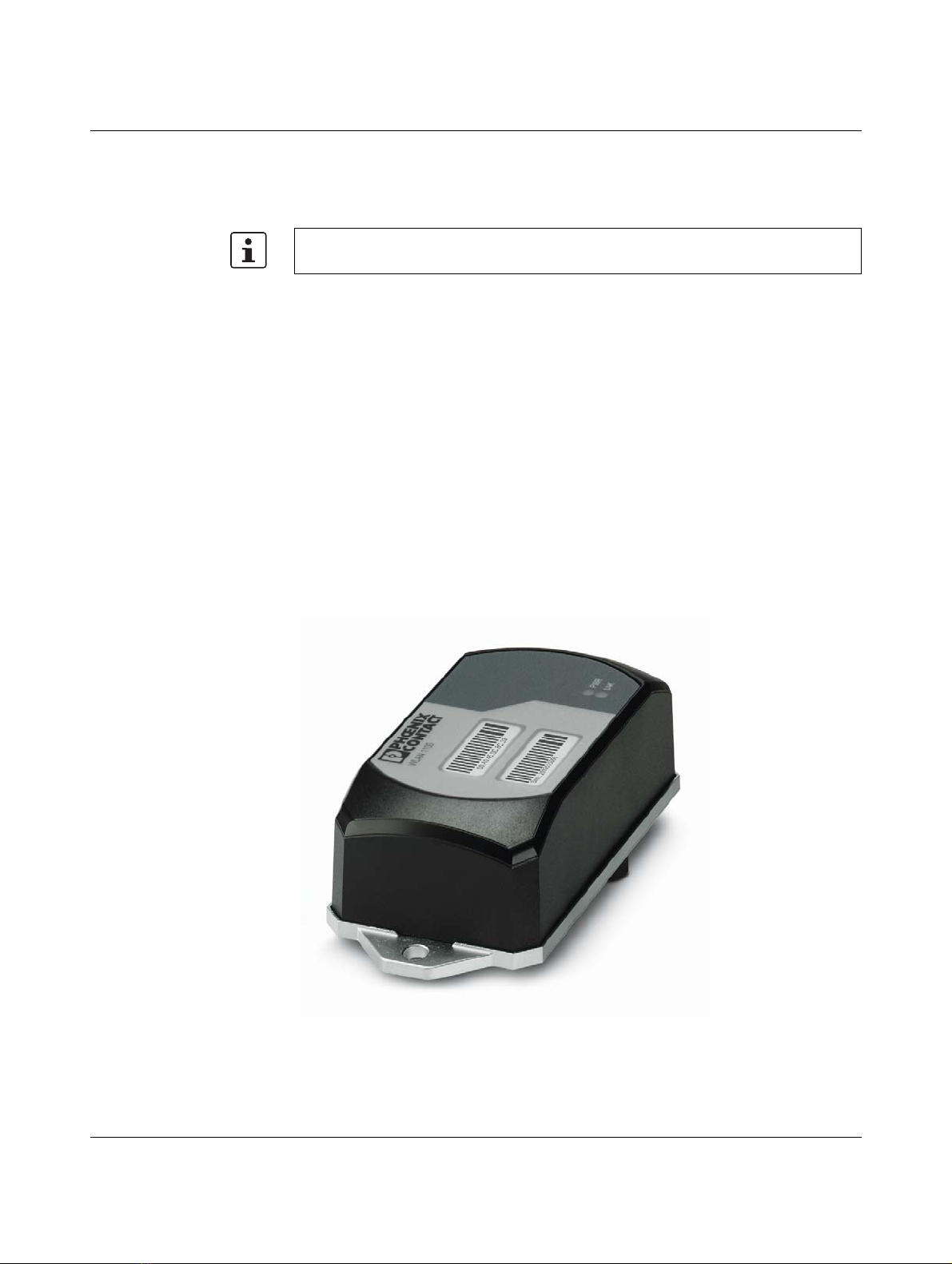
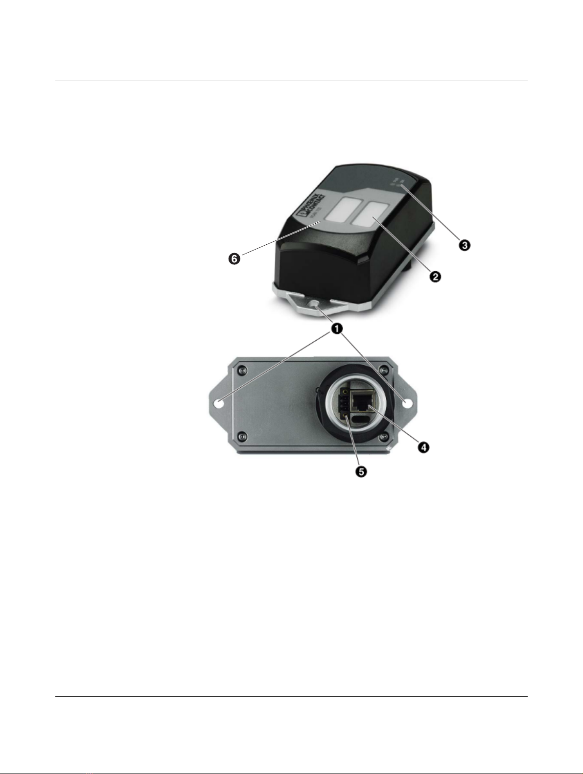
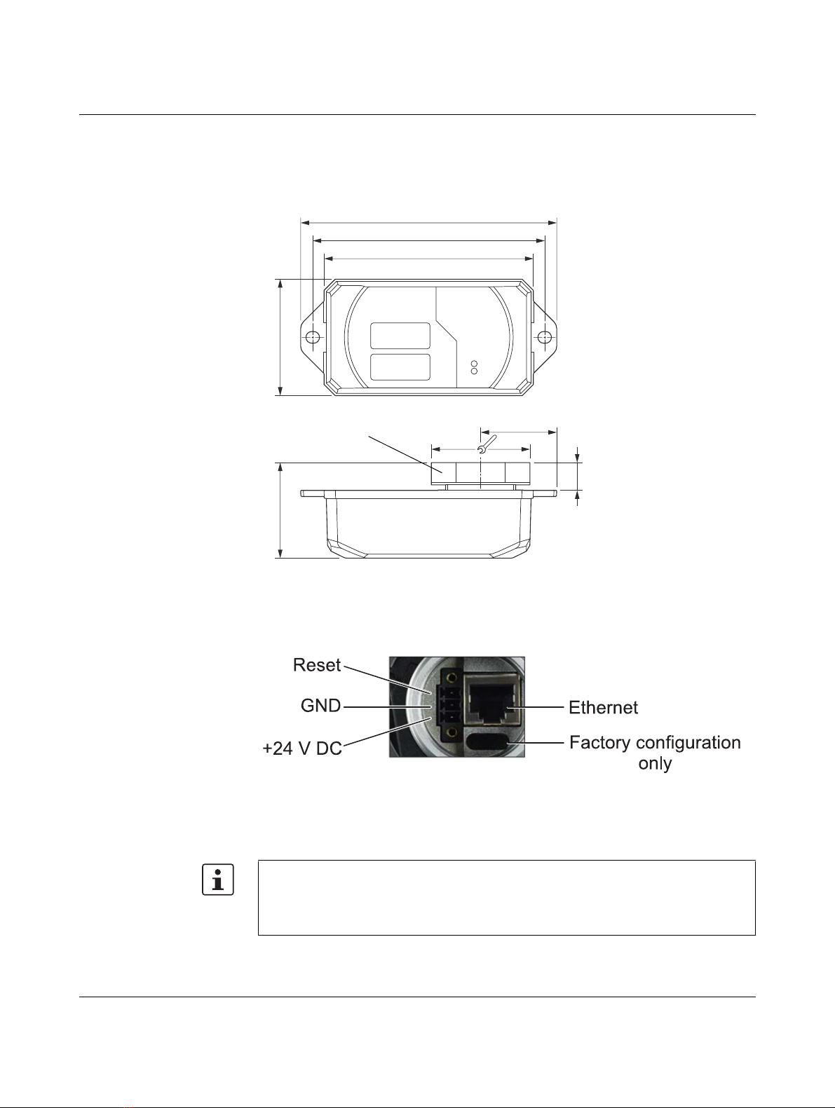
Phoenix Contact FL WLAN 1100 User manual

Technical description
107390_en_01 PHOENIX CONTACT 7
1 Technical description
1.1 General description
Robust, compact WLAN module with integrated antennas:
– Turnkey solution with integrated antenna and wireless module in a single device
– Space savings in the control cabinet, optimized for mounting directly on machines, mo-
bile units or control cabinets
– Fast and reliable wireless communication, thanks to powerful MIMO antennas
– Quick and easy connection, thanks to single-hole mounting
– Extremely robust housing, shock-proof according to IK08
– Operation as a WLAN access point, client or repeater
– Supports WLAN 802.11 standards a, b, g, and n
– Operation in the 2.4 GHz and 5 GHz band
Figure 1-1 FL WLAN 1100
Unless otherwise expressly stated, all information provided in this user manual always ap-
plies to both the FL WLAN 1100 and the FL WLAN 1101.

FL WLAN 1000/2000
8PHOENIX CONTACT 107390_en_01
1.2 FL WLAN 110x country registrations
1.2.1 FL WLAN 1100
The FL WLAN 1100 is a WLAN device with access point and client functionality. The device
uses the WLAN standard in the license-free 2.4 GHz and 5 GHz bands which are free of
charge. It is approved for use in Europe.
Approvals for other countries are available on request.
1.2.2 FL WLAN 1101
Furthermore, the following approvals have been performed and passed for the FL WLAN
1101 device:
– FCC/CFR 47, Part 15 (USA)
– RSS 210 (Canada)
1.2.2.1 FCC information
Note: This equipment has been tested and found to comply with the limits for a Class A dig-
ital device, pursuant to part 15 of the FCC Rules. These limits are designed to provide rea-
sonable protection against harmful interference when the equipment is operated in a com-
mercial environment. This equipment generates, uses, and can radiate radio frequency
energy and, if not installed and used in accordance with the instruction manual, may cause
harmful interference to radio communications. Operation of this equipment in a residential
area is likely to cause harmful interference in which case the user will be required to correct
the interference at his own expense.
NOTICE:
This Class A digital apparatus complies with Canadian ICES-003. Cet appareil numérique
de la classe A est conforme à la norme NMB-003 du Canada.
NOTICE:
This device complies with Part 15 of the FCC Rules and with Industry Canada licence-ex-
empt RSS standard(s).
Operation is subject to the following two conditions:
An up-to-date list of additional country registrations can be found in the e-shop at phoe-
nixcontact.net/product/2702534.
Make sure you observe the regulations of the relevant regulatory body for device opera-
tion in all countries.
The FL WLAN 1101 device, Order No. 2702538, can be used in the USA and Canada. It
does not have CE approval and may not be operated in Europe. It is only available for ex-
port.

Technical description
107390_en_01 PHOENIX CONTACT 9
1this device may not cause harmful interference, and
2this device must accept any interference received, including interference that may cau-
se undesired operation.
Le présent appareil est conforme aux CNR d'Industrie Canada applicables aux appareils
radio exempts de licence. L'exploitation est autorisée aux deux conditions suivantes:
1l'appareil ne doit pas produire de brouillage, et
2l'appareil doit accepter tout brouillage radioélectrique subi, même si le brouillage est
susceptible d'en compromettre le fonctionnement.
NOTICE:
Changes or modifications made to this equipment not expressly approved by Phoenix Con-
tact GmbH & Co. KG may void the FCC authorization to operate this equipment.
Radiofrequency radiation exposure Information:
This equipment complies with FCC and IC radiation exposure limits set forth for an uncon-
trolled environment. This equipment should be installed and operated with minimum dis-
tance of 20 cm between the radiator and your body.
This transmitter must not be co-located or operating in conjunction with any other antenna
or transmitter.
Cet équipement est conforme aux limites d'exposition aux rayonnements IC établies pour
un environnement non contrôlé. Cet équipement doit être installé et utilisé avec un minimum
de 20 cm de distance entre la source de rayonnement et votre corps.
Ce transmetteur ne doit pas etre place au meme endroit ou utilise simultanement avec un
autre transmetteur ou antenne.

FL WLAN 1000/2000
10 PHOENIX CONTACT 107390_en_01
1.3 Firmware
Table 1-1
Firmware version Functions
FW 1.0x Initial version
Additional information on the latest firmware changes for the respective product can be
found in the e-shop at phoenixcontact.com or at phoenixcontact.net/product/2702534.

Mounting/antenna configuration
107390_en_01 PHOENIX CONTACT 11
2 Mounting/antenna configuration
2.1 Connections and operating elements
Figure 2-1 Connections and operating elements of the device
1. Mounting holes
2. Marking fields
3. Status and diagnostic LEDs
4. Ethernet connection in RJ45 format with 100 Mbps
5. Connections for supply voltage and one digital input via COMBICON
6. Two integrated WLAN antennas

FL WLAN 1100/1101
12 PHOENIX CONTACT 107390_en_01
2.1.1 Housing dimensions
The outside dimensions of the FL WLAN 1100 and FL WLAN 1101 devices are 62.8 mm x
36.5 mm x 113.2 mm (width x height x depth).
Figure 2-2 Housing dimensions and distances
2.1.2 Electrical connection
Figure 2-3 Connection of the supply voltage, Ethernet, and the reset input
The supplied connector is an FMC 1,5/ 3-STF-3,5 (Order No. 1966101).
A cable with a cross section of 0.75 mm2and a trapezoidal or square crimped ferrule that
is 10 mm long is recommended.
Always use the appropriate conductor cross section and ferrules to ensure that the cable
is fixed securely.
M40

Mounting/antenna configuration
107390_en_01 PHOENIX CONTACT 13
2.1.2.1 Assignment of the RJ45 Ethernet connectors
2.1.2.2 Grounding of the device
Table 2-1 Connection data for the connector
Conductor cross section solid/stranded min. 0.2 mm2
Conductor cross section solid/stranded max. 1.5 mm2
Conductor cross section stranded with ferrule without plastic
sleeve min.
0.25 mm2
Conductor cross section stranded with ferrule without plastic
sleeve max.
1.5 mm2
Conductor cross section stranded with ferrule with plastic sleeve
min.
0.25 mm2
Conductor cross section stranded with ferrule with plastic sleeve
max.
0.75 mm2
Conductor cross section AWG min. 24
Conductor cross section AWG max. 16
Conductor cross section AWG min. according to UL/CUL 24
Conductor cross section AWG max. according to UL/CUL 16
Table 2-2 Pin assignment of RJ45 connectors
Pin number 10Base-T/10 Mbps 100Base-T/100 Mbps
1 TD+ (transmit) TD+ (transmit)
2 TD- (transmit) TD- (transmit)
3 RD+ (receive) RD+ (receive)
4- -
5- -
6 RD- (receive) RD- (receive)
7- -
8- -
Grounding protects people and machines against hazardous voltages. To avoid these
dangers, as far as possible, correct grounding, taking the local conditions into account, is
vital.
Functional grounding of the device:
The device must be connected to ground (functional earth ground) via the metal part of
the housing. If this is not possible, ensure a low-resistance ground connection (functional
earth ground) for the shielding of the Ethernet cable.

FL WLAN 1100/1101
14 PHOENIX CONTACT 107390_en_01
FL WLAN 1100 and FL WLAN 1101: it is recommended that the base plate of the device is
grounded by connecting the mounting screws to a grounded metal surface (functional earth
ground/FE).
If this is not possible, e.g., because the device is installed on a plastic surface, you must
make sure that the Ethernet cable is properly shielded. This is particularly important if the
housing is not grounded by other means, e.g., via the base plate.
2.1.3 Mounting the device on a level surface
The devices in the FL WLAN 110x series are designed for external mounting on control cab-
inets, machines, automatic guided vehicle (AGV) systems or similar equipment.
To mount the device on a level surface, a bore hole is required for the mounting flange (40
mm in diameter). The nut must be tightened (8 - 10 Nm maximum) to ensure a tight seal.
The device can be additionally secured to the surface with two screws (M6). When using
this additional screw connection, make sure that the entire system is sealed tight.
The device can be installed in any mounting position.
Figure 2-4 Mounting on a level surface

Mounting/antenna configuration
107390_en_01 PHOENIX CONTACT 15
2.1.3.1 Drill hole template
Figure 2-5 Drill hole template (original size)

FL WLAN 1100/1101
16 PHOENIX CONTACT 107390_en_01
2.1.4 Mounting the device with cable feed-through and seal
When mounting the device outside the control cabinet (e.g., on a mounting bracket), a cable
feed-through with seal can be used to seal the connection dome for the supply line. The
metal cable feed-through (FL M32 ADAPTER, Order No. 2702544) screws into the M32 in-
ternal thread of the FL WLAN 1100 connection dome. The FL WLAN 1100 is therefore
sealed to IP54 even outdoors.
Figure 2-6 Mounting on a mounting bracket. If the device is not mounted directly on a
control cabinet, use the FL M32 ADAPTER (Order No. 2702544) to create
the seal.

Mounting/antenna configuration
107390_en_01 PHOENIX CONTACT 17
2.1.4.1 Handling the FL M32 ADAPTER
Figure 2-7 Handling the FL M32 ADAPTER
2.1.4.2 Tightness of seal, retention, and strain relief (in accordance with EN
50262)
Tightening torque (double nipple): 15 Nm for M32
Tightening torque (pressure screw): 20 Nm for Pg29
Tightness of seal for 7 mm hole pattern and 8.5 mm for cable:
IP65 protection is achieved in accordance with DIN EN 60529(2014.09) if the difference be-
tween the cable diameter and hole is less than 10%.
If both are the same, IP68 can be achieved up to 10 bar with defined “retention” in accor-
dance with EN 50262 Class A. The tightness of seal and strain relief depend on the cable
used.
2.1.4.3 Mounting taking the internal antennas into consideration
The FL WLAN 1100 has two internal antennas which transmit through the plastic housing.
This must be taken into consideration when mounting the device: in order to ensure that the
WLAN signal can be transmitted via the built-in antennas, the device must not be installed
inside control cabinets or other metal housings.
The devices in the FL WLAN 110x series have internal antennas for WLAN communica-
tion. The device should therefore be mounted on the outside of metal objects so as to en-
sure that the WLAN signal can be transmitted.
Other manuals for FL WLAN 1100
2
Table of contents
Other Phoenix Contact Wireless Access Point manuals
Popular Wireless Access Point manuals by other brands

Aruba
Aruba AP-92 installation guide

Alcatel-Lucent
Alcatel-Lucent OAW-AP228 installation guide

Extreme Networks
Extreme Networks ExtremeWireless AP5010 installation guide

Enable-IT
Enable-IT 5 Mile 150Mbps WiFi Bridge manual

TRENDnet
TRENDnet TEW-410APB Quick installation guide

Draytek
Draytek VigorAP 1000C quick start guide