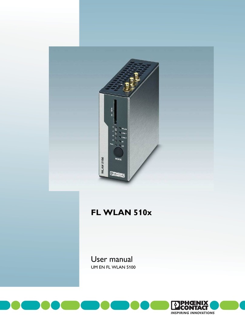
Phoenix Contact UM EN FL WLAN 5100 User manual

User manual
UM EN FL WLAN 5100
UM EN FL WLAN 5100

2013-06-05
PHOENIX CONTACT 7191_en_04
UM EN FL WLAN 5100
UM EN FL WLAN 5100
04
—
Designation Revision Order No.
FL WLAN 5100 2700718
FL WLAN 5101 2701093
User manual
Designation:
Revision:
Order No.:
This user manual is valid for:

PHOENIX CONTACT
Please observe the following notes
User group of this manual
The use of products described in this manual is oriented exclusively to qualified electricians
or persons instructed by them, who are familiar with applicable standards and other regula-
tions regarding electrical engineering and, in particular, the relevant safety concepts.
Explanation of symbols used and signal words
How to contact us
Internet Up-to-date information on Phoenix Contact products and our Terms and Conditions can be
found on the Internet at:
www.phoenixcontact.com
Make sure you always use the latest documentation.
It can be downloaded at:
www.phoenixcontact.net/catalog
Subsidiaries If there are any problems that cannot be solved using the documentation, please contact
your Phoenix Contact subsidiary.
Subsidiary contact information is available at www.phoenixcontact.com.
Published by PHOENIX CONTACT GmbH & Co. KG
Flachsmarktstraße 8
32825 Blomberg
GERMANY
Should you have any suggestions or recommendations for improvement of the contents and
layout of our manuals, please send your comments to:
tecdoc@phoenixcontact.com
This is the safety alert symbol. It is used to alert you to potential personal injury
hazards. Obey all safety measures that follow this symbol to avoid possible in-
jury or death.
There are three different categories of personal injury that are indicated with a
signal word.
DANGER This indicates a hazardous situation which, if not avoided, will re-
sult in death or serious injury.
WARNING This indicates a hazardous situation which, if not avoided, could
result in death or serious injury.
CAUTION This indicates a hazardous situation which, if not avoided, could
result in minor or moderate injury.
This symbol together with the signal word NOTE and the accompanying text
alert the reader to a situation which may cause damage or malfunction to the
device, hardware/software, or surrounding property.
This symbol and the accompanying text provide the reader with additional in-
formation or refer to detailed sources of information.

Please observe the following notes
PHOENIX CONTACT
General terms and conditions of use for technical documentation
Phoenix Contact reserves the right to alter, correct, and/or improve the technical documen-
tation and the products described in the technical documentation at its own discretion and
without giving prior notice, insofar as this is reasonable for the user. The same applies to any
technical changes that serve the purpose of technical progress.
The receipt of technical documentation (in particular user documentation) does not consti-
tute any further duty on the part of Phoenix Contact to furnish information on modifications
to products and/or technical documentation. You are responsible to verify the suitability and
intended use of the products in your specific application, in particular with regard to observ-
ing the applicable standards and regulations. All information made available in the technical
data is supplied without any accompanying guarantee, whether expressly mentioned, im-
plied or tacitly assumed.
In general, the provisions of the current standard Terms and Conditions of Phoenix Contact
apply exclusively, in particular as concerns any warranty liability.
This manual, including all illustrations contained herein, is copyright protected. Any
changes to the contents or the publication of extracts of this document is prohibited.
Phoenix Contact reserves the right to register its own intellectual property rights for the
product identifications of Phoenix Contact products that are used here. Registration of such
intellectual property rights by third parties is prohibited.
Other product identifications may be afforded legal protection, even where they may not be
indicated as such.

Table of contents
7179_en_04 PHOENIX CONTACT 5
Table of contents
1 Technical description .................................................................................................................8
1.1 General description ............................................................................................... 8
1.2 FL WLAN 510x country registrations ..................................................................... 9
1.2.1 FL WLAN 5100 ...................................................................................... 9
1.2.2 FL WLAN 5101 ...................................................................................... 9
1.3 Firmware ............................................................................................................. 12
2 Mounting ..................................................................................................................................13
2.1 Connections and operating elements .................................................................. 13
2.1.1 Electrical connection ............................................................................ 14
2.1.2 Mounting .............................................................................................. 14
3 Startup and configuration .........................................................................................................19
3.1 Status and diagnostic indicators ......................................................................... 20
3.1.1 Meaning of the LAN1/2 indicators ........................................................ 21
3.1.2 Meaning of the LEDs as signal quality indicators in client mode .......... 21
3.2 Configuration using the MODE button ................................................................. 21
3.2.1 General sequence ............................................................................... 22
3.2.2 Changing the firmware image using the MODE button ........................ 23
3.2.3 Connection to a PC .............................................................................. 24
3.2.4 Assigning the IP address via BootP (with IPAssign) ............................. 25
3.2.5 IP address assignment using IPAssign.exe .........................................25
3.2.6 Using the digital input and output ......................................................... 28
3.3 Startup via the web interface ............................................................................... 28
3.3.1 General information in the web interface .............................................. 29
3.4 Quick setup ......................................................................................................... 31
3.4.1 Operation as an access point ............................................................... 34
3.4.2 Operation as a client ............................................................................ 36
3.5 SD card for saving the device configuration ........................................................ 40
3.5.1 Inserting the SD card ........................................................................... 41
3.5.2 Saving the device configuration ........................................................... 42
3.6 Firmware update.................................................................................................. 43
3.6.1 HTTP ................................................................................................... 43
3.6.2 TFTP .................................................................................................... 43
3.6.3 Via SD card .......................................................................................... 43
3.6.4 Via BootP/TFTP ................................................................................... 44
3.7 Operating modes of the device............................................................................ 45
3.7.1 Operating mode: access point ............................................................. 45
3.7.2 Operating mode: client ......................................................................... 46
3.7.3 Operating mode: repeater .................................................................... 49
3.7.4 Operating mode: machine admin ......................................................... 52

FL WLAN 5100
6PHOENIX CONTACT 7179_en_04
3.8 PROFINET assistance mode............................................................................... 54
3.8.1 WLAN in PROFINET applications ........................................................ 54
3.9 Wi-Fi Protected Setup (WPS)..............................................................................56
3.9.1 Running WPS using the MODE button ................................................. 56
3.10 Quality of service ................................................................................................. 56
3.11 Cluster management ........................................................................................... 57
3.11.1 Searching and selecting cluster devices .............................................. 57
3.11.2 Identifying cluster-relevant parameters in the web interface ................ 62
3.11.3 Properties of cluster management ....................................................... 63
3.12 Using file transfer................................................................................................. 63
3.13 DHCP server ....................................................................................................... 64
3.14 Event handling..................................................................................................... 65
3.14.1 Selecting events in web-based management ...................................... 66
4 Menu/functions ........................................................................................................................69
4.1 Parameter list for the configuration ...................................................................... 70
5 Diagnostics ..............................................................................................................................83
5.1 WLAN signal strength diagnostics on the client................................................... 83
5.2 Diagnostics of WLAN channel assignment on the access point .......................... 85
6 Technical data .........................................................................................................................87
6.1 Ordering data ...................................................................................................... 89

7191_en_03 PHOENIX CONTACT 7
WLAN 5100 – next generation industrial WLAN
Industrial WLAN network solutions from Phoenix Contact open up new possibilities for
creating production and logistics processes more efficiently, reliably, and simply. The fields
of application are:
•Reliable, safe and fast communication with mobile or moving automation and
production systems.
•Realtime access to network resources and service information for increasing
productivity and accelerating decision processes.
The WLAN modules in the 510x series offer maximum reliability, data throughput, and
range. The new WLAN 510x combines rugged industrial technology with high 802.11n
performance and modern MiMo (multiple input, multiple output) antenna technology in
extremely compact metal housing. MiMo technology with three antennas significantly
increases the ruggedness, speed, and range of your wireless communication. This is
particularly noticeable under challenging industrial conditions.
A special feature of the WLAN 510x modules is their quick and easy configuration. The
configuration of a WLAN access point is automatically distributed to all other access points
in the WLAN network using the cluster management function. At the touch of a button,
WLAN clients can also be integrated easily into the WLAN network without configuration
thanks to WPS (Wi-Fi Protected Setup).

FL WLAN 510x
8PHOENIX CONTACT 7191_en_03
1 Technical description
1.1 General description
Compact wireless access point/client with the following properties:
– Operation as a WLAN access point, repeater or client
– Supports WLAN 802.11 standards: a, b, g, n
– Operation in the ISM band at 2.4 GHz frequency or in the 5 GHz band
– IP20 degree of protection
– Connections: COMBICON for supply voltage (10 ... 36 V DC), 2 x RJ45 ports for LAN
– Configuration via WBM, SNMP, and CLI via SSH/Telnet
– Security functions: 802.11i: WPA2, WPA-PSK, TKIP, AES
– Connections for three antennas (MiMo technology/connection method:
RSMA/not supplied as standard)
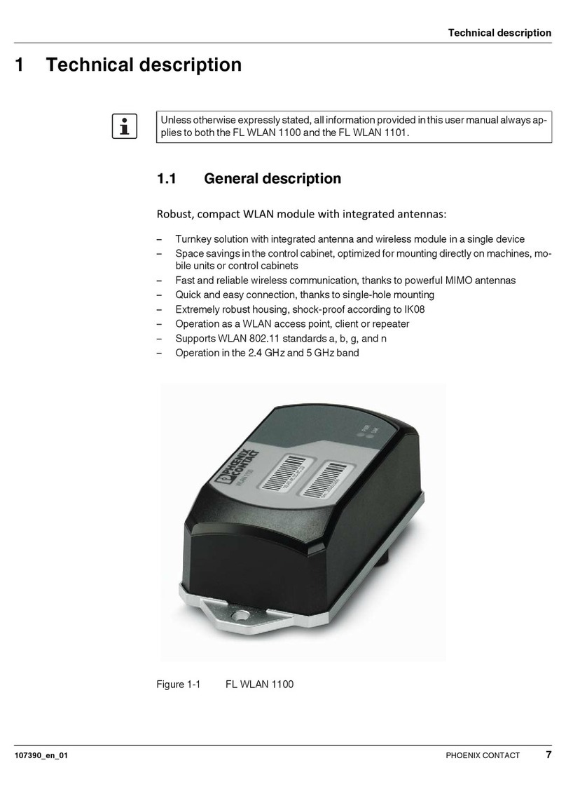
Figure 1-1 FL WLAN AP 5100
Unless otherwise expressly stated, all information provided in this user manual always
applies to both the FL WLAN 5100 and the FL WLAN 5101.

Technical description
7191_en_03 PHOENIX CONTACT 9
1.2 FL WLAN 510x country registrations
1.2.1 FL WLAN 5100
The FL WLAN 5100 is a WLAN device with access point and client functionality. The device
uses the WLAN standard in the license-free 2.4 GHz and 5 GHz bands which are free of
charge.
The device meets all the requirements of R&TTE directive 1999/5/EC (Europe):
– EMC according to EN 61000-6-2:2005
– Safety according to EN 60950-1:2006+A11
– Health according to EN 50371
– EN 301 893 V1.5.1 (5 GHz), EN 300 328 V1.7.1 (2.4 GHz), EN 301 489-01 V1.8.1,
and EN 301 489-17 V2.1.1
Depending on the maximum possible transmission power, device operation must be
approved or registered in some countries. Furthermore, there may be a usage restriction on
the transmission power.
Approvals for other countries are available on request.
1.2.2 FL WLAN 5101
In addition, the following approvals have been performed and passed for the
FL WLAN 5101 device (Order No. 2701093):
– FCC/CFR 47, Part 15 (USA)
– RSS 210 (Canada)
1.2.2.1 FCC information
FCC Statement
This equipment has been tested and found to comply with the limits for a Class B digital
device, pursuant to Part 15 of the FCC rules. These limits are designed to provide
reasonable protection against harmful interference in a residential installation. This
equipment generates, uses and can radiate radio frequency energy and, if not installed and
used in accordance with the instructions, may cause harmful interference to radio
communications.
An up-to-date list of the country registrations can be found in the e-shop at
phoenixcontact.com.
Make sure you observe the regulations of the relevant regulatory domain for device
operation in all countries.
The FL WLAN 5101 device, Order No. 2701093, does not have CE approval and may not
be operated in Europe. It is only available for export.

FL WLAN 510x
10 PHOENIX CONTACT 7191_en_03
However, there is no guarantee that interference will not occur in a particular installation. If
this equipment does cause harmful interference to radio or television reception, which can
be determined by turning the equipment off and on, the user is encouraged to try to correct
the interference by one of the following measures:
– Reorient or relocate the receiving antenna.
– Increase the separation between the equipment and receiver.
– Connect the equipment into an outlet on a circuit different from that to which the receiver
is connected.
– Consult the dealer or an experienced radio/TV technician for help.
To comply with FCC part 15 rules in the United States, the system must be professionally
installed to ensure compliance with the Part 15 certification. It is the responsibility of the
operator and professional installer to ensure that only certified systems are deployed in the
United States. The use of the system in any other combination (such as co-located
antennas transmitting the same information) is expressly for bidden.
FCC Caution
Any changes or modifications not expressly approved by the party responsible for
compliance could void the users authority to operate this equipment.
This device complies with Part 15 of the FCC Rules. Operation is subject to the following
two conditions: (1) this device may not cause harmful interference, and (2) this device must
accept any interference received, including interference that may cause undesired
operation.
operated. Selection of other channels is not possible.
This device and its antenna(s) must not be co-located or operation in conjunction with any
other antenna or transmitter.
If this device is going to be operated in 5.15~5.25GHz frequency range, it is restricted in
indoor environment only.
FCC Radiation Exposure Statement
This equipment complies with FCC radiation exposure limits set forth for an uncontrolled
environment. This equipment should be installed and operated with minimum distance
20cm between the radiator & your body.
IC Statement
This Class B digital apparatus complies with Canadian ICES-003.
Cet appareil numérique de la classe B conforme á la norme NMB-003 du Canada.
This device complies with Industry Canada license-exempt RSS standard(s). Operation this
subject to the following two conditions: (1) this device may not cause interference, and (2)
this device must accept any interference, including interference that may cause undesired
operation of the device.

Technical description
7191_en_03 PHOENIX CONTACT 11
Le présent appareil est conforme aux CNR d`Industrie Canada applicables aux appareils
radio exempts de licence. L`exploitation est autorisèe aux deux conditions suivantes: (1)
l`appareil ne doit pas produire de brouillage, et (2) l`utilisateur de l`appareil doit accepter
tout brouillage radioèlectrique subi, mème si le brouillage est susceptible d`en
compromettre le fonctionnement.
For product available in the USA/Canada market, only channel 1~11 can be operated.
Selection of other channels is not possible.
This device and its antenna(s) must not be co-located or operation in conjunction with any
other antenna or transmitter.
Under Industry Canada regulations, this radio transmitter may only operate using an
antenna of a type and maximum (or lesser) gain approved for the transmitter by Industry
Canada. To reduce potential radio interference to other users, the antenna type and its gain
should be so chosen that the equivalent isotropically radiated power (e.i.r.p.) is not more
than that necessary for successful communication.
This radio transmitter (identify the device by certification number, or model number if
Category II) has been approved by Industry Canada to operate with the antenna types listed
below with the maximum permissible gain and required antenna impedance for each
antenna type indicated. Antenna types not included in this list, having a gain greater than
the maximum gain indicated for that type, are strictly prohibited for use with this device.
The device could automatically discontinue transmission in case of absence of information
to transmit, or operational failure. Note that this is not intended to prohibit transmission of
control or signaling information or the use of repetitive codes where required by the
technology.
Dynamic Frequency Selection (DFS) for devices operating in the bands 5250-5350 MHz,
5470-5600 and 5650-5725 MHz.
The maximum antenna gain permitted for devices in the band 5725-5825 MHz shall comply
with the e.i.r.p. limits specified for point-to-point and non point-to-point operation as
appropriate.
Users should also be advised that high-powers radars are allocated as primary users (i.e.
priority users) of the bands 5250-5350 MHz and 5650-5850 MHz and that these radars
could cause interference and/or damage to LE-LAN devices.
IMPORTANT NOTE:
IC Radiation Exposure Statement:
This equipment complies with IC RSS-102 radiation exposure limits set forth for an
uncontrolled environment. This equipment should be installed and operated with minimum
distance 20cm between radiator & your body.
This module is intended for OEM integrator. The OEM integrator is still responsible for the
IC compliance requirement of the product, which integrates this module.
20cm minimum distance has to be able to be maintained between the antenna and the
users for the host this module is integrated into. Under such configuration, the IC RSS-102
radiation exposure limits set forth for a population/uncontrolled environment can be
satisfied.
Any changes or modifications not expressly approved by the manufacturer could void the
users authority to operate this equipment.

FL WLAN 510x
12 PHOENIX CONTACT 7191_en_03
1.3 Firmware
Table 1-1
Firmware version Functionality
FW 1.60 The “machine admin mode” (second SSID) and DHCP server func-
tions are available as of this FW version.

Mounting
7191_en_03 PHOENIX CONTACT 13
2Mounting
2.1 Connections and operating elements
Figure 2-1 Connections and operating elements of the device
1. COMBICON connections for supply voltage and one digital input or output (X3)
2. Two RJ45 Ethernet connections with 100 Mbps (X1, X2)
3. Mode button for setting various pre-configured states
4. Status and diagnostic LEDs
5. Slot for optional SD memory card (X4)
6. RSMA antenna connections (female) (X5, X6, X7)
X4 MEM
WLAN 5100
MODE
WLAN
D
C
B
A
FAIL
LAN 1
LAN 2
DI
US
1
2
3
4
5
X4 MEM
WLAN 5100
MODE
WLAN
D
C
B
A
FAIL
LAN1
LAN2
DI
US
6
X5
X6
X7

FL WLAN 510x
14 PHOENIX CONTACT 7191_en_03
2.1.1 Electrical connection
Figure 2-2 Connecting the supply voltage and the input/output
2.1.2 Mounting
2.1.2.1 DIN rail mounting
Use the DIN rail guide to position the module onto the upper edge of the DIN rail, and snap
the module into place by pushing it downward.
Figure 2-3 Snapping the module onto the DIN rail
When using remote antennas, always keep the antenna cable as short as possible to
avoid an attenuation of the wireless signal.
Preferably use the mounting position illustrated in the following graphic.
A1
A2

Mounting
7191_en_03 PHOENIX CONTACT 15
2.1.2.2 Removal
Insert a suitable tool (e.g., flat-bladed screwdriver) into the latch and pull the latch
downward (B1).
Figure 2-4 Removing the module from the DIN rail
2.1.2.3 Housing dimensions
Figure 2-5 Housing dimensions with protruding parts in mm
B1
B2
X4
D WLAN
LAN 1
LAN 2
DI
US
C
B
A
FAIL
MODE
WLAN 5100
MEM
109
100
40
115

FL WLAN 510x
16 PHOENIX CONTACT 7191_en_03
2.1.2.4 Wall mounting
The FL WLAN 5100 PA mounting kit (Order No. 2701092) can be used to mount the device
on a wall.
Figure 2-6 Securing the mounting kit
Use the two screws provided to secure the device to the base plate.
The two 4.5 mm bore holes can be used for mounting.
2.1.2.5 Dimensions of the mounting kit and drill hole template
Figure 2-7 Dimensions of the mounting kit and drill hole template in mm
Preferably use the mounting position illustrated in the following graphic.
X4 MEM
WLAN 5100
MODE
WLAN
D
C
B
A
FAIL
LAN1
LAN2
DI
US
X4
DW
LAN
LAN1
LAN2
DI
US
C
B
A
FAIL
MODE
WLAN 5100
MEM
125
140
95
64
Ø4,2
9,2

Mounting
7191_en_03 PHOENIX CONTACT 17
2.1.2.6 Mounting in the IP65 housing
Phoenix Contact offers an IP65 housing (FL RUGGED BOX OMNI-1) specifically for use in
conjunction with the FL WLAN 510x. Three omnidirectional antennas (dual band, 2.4 GHz,
and 5 GHz) are supplied as standard with the housing. They are screwed directly onto the
housing. Also included are three antenna connecting cables, the necessary DIN rail (144
mm), plus cable feed-throughs. The WLAN access point is not supplied as standard.
Housing dimensions of FL RUGGED BOX OMNI-1
Width: 180 mm
Height: 250 mm
Depth: 140 mm
Figure 2-8 IP65 protective housing with antennas and cable feed-throughs
Additional rugged box versions can be found at phoenixcontact.com:
FL RUGGED BOX, Order No. 2701204
FL RUGGED BOX OMNI-2, Order No. 2701439
FL RUGGED BOX DIR-1, Order No. 2701440
2.1.2.7 Antenna mounting distances
The WLAN 510x supports the MIMO (multiple input multiple output) antenna technology. Up
to three antennas are used which are connected to connections X5, X6, X7. The antennas
should be connected via an antenna cable outside the control cabinet, so they can radiate

FL WLAN 510x
18 PHOENIX CONTACT 7191_en_03
well into the area. This means that the radiating element of the antenna should not be
located too close to conductive objects, if possible. Keep a distance of more than 200 mm,
if possible. Smaller distances are possible, however, they may affect radiation.
Figure 2-9 Correct and wrong antenna mounting using an omnidirectional antenna as
an example
Distance of the antennas from one another
The distance between the three antennas of a device must at least be 80 mm each to
ensure decoupling of the data streams that are transmitted in parallel (MIMO technology). If
larger distances of approximately 200 mm to 500 mm between the antennas are
mechanically feasible, this may lead to further improvement.
For the same reason, antennas should not be screwed directly onto the device.
Figure 2-10 Do not screw several antennas onto the device.

Startup and configuration
7191_en_03 PHOENIX CONTACT 19
3 Startup and configuration
Installation notes
The category 3 device is designed for installation in the potentially explosive area of zone 2.
It meets the requirements of EN 60079-0:2009 and EN 60079-15:2010.
Installation, operation, and servicing may only be carried out by qualified electricians.
Follow the installation instructions as described. When installing and operating the device,
the applicable regulations and safety directives (including national safety directives), as well
as general technical regulations, must be observed. The safety data is provided in this user
manual and on the certificates (conformity assessment, additional approvals where
applicable).
Do not open or modify the device. Do not repair the device yourself but replace it with an
equivalent device. Repairs may only be performed by the manufacturer. The manufacturer
is not liable for harm resulting from noncompliance.
The IP20 degree of protection (IEC 60529/EN 60529) of the device is intended for use in a
clean and dry environment. Do not subject the device to mechanical and/or thermal loads
that exceed the specified limits.
The device is not suitable for installation in zone 22.
If, however, you wish to use the device in zone 22, it must be installed in a housing that
complies with EN 60079-0. In doing so, observe the maximum surface temperatures.
Adhere to the requirements of EN 60079-14.
Installation in zone 2
Observe the specified conditions for use in potentially explosive areas! When installing the
device, use an appropriate and approved housing with a minimum protection of IP54. At the
same time, observe EN 60079-14 requirements.
Only devices which are designed for operation in zone 2 and are suitable for the conditions
at the installation location may be connected to the supply and signal circuits in zone 2.
In potentially explosive areas, only connect and disconnect cables when the power is
disconnected.
You must only work on the device if it has been ensured that there is no explosive
environment.
The device must be stopped and immediately removed from the Ex area if it is damaged,
was subjected to an impermissible load, stored incorrectly or if it malfunctions.
In addition for FL WLAN 5100:
Ensure that the radiated wireless power is neither bundled (focused) by the antenna itself
nor by any inserts in the environment of the antenna, and that it cannot enter neighboring
zones 1 or 0. Please refer to the technical data for the transmission power.
Application note:
The HF antenna cable must be suitable for the ambient conditions and should be installed
in a way that it is protected against mechanical damage, corrosion, chemical stress, and the
effects of heat or UV radiation. The same applies to the antenna which is connected to the
cable and which functions as a cable termination.
The antenna must meet the requirements of EN 60079-0 with regard to housing and
electrostatic discharge.

FL WLAN 510x
20 PHOENIX CONTACT 7191_en_03
This section describes a typical startup of the WLAN device as an access point or client
using the “Quick Setup” feature. A standard WLAN network can be established in this way.
For special applications and configuration, further details can be found in “Menu/functions”
on page 69.
3.1 Status and diagnostic indicators
Figure 3-1 Status and diagnostic indicators
1. LEDs A, B, C, and D indicate the relevant state of the device while it is being configured
using the MODE button. For details, see the sticker on the side of the device or
“Configuration using the MODE button” on page 21.
In WLAN operation as a client, the LEDs indicate the signal strength of the connected
device (see “Meaning of the LEDs as signal quality indicators in client mode” on
page 21).
2. Fail:
Lights up red if no configuration has been received in WPS mode, the link quality LEDs
also flash yellow.
3. WLAN status:
WLAN connection established (blue)
Whether data transmission occurs depends on whether the passwords and certificates
are valid. A WLAN connection can therefore exist even if data cannot be transmitted. If
WLAN authentication fails, this is indicated in the log file.
Half duplex data transmission: blue; if flashing, data transmission is active
NOTE:
The device must only ever be operated when an antenna is present at the activated
antenna connection. The antenna connections can be deactivated under “Advanced
WLAN” in the web interface.
Do not screw more than one omnidirectional antenna onto the device. The distance of the
antenna connectors has been optimized for installation in control cabinets and the use of
antenna cables. To ensure decoupling the distance between the antennas should be at
least 80 mm. A larger distance may improve the performance of the device.
1
2
3
4
5
6
7
Other manuals for UM EN FL WLAN 5100
1
Table of contents
Other Phoenix Contact Wireless Access Point manuals