Phoenix International VL1-250-SC-DS Manual

VL1-250-SC-DS
MASS STORAGE SUBSYSTEM
Technical Information
Copyright ©Phoenix International 2005. All Rights Reserved
812 W. Southern Avenue, Orange, CA 92865

PREFACE
A number of conventions are used throughout this manual in order to provide clarity and
descriptive accuracy. These include:
1. The use of an 'H' (character) suffix to a number indicates that the number reference is
in hexadecimal notation.
2. The use of a '-' (minus) postfix to a signal name indicates that the signal is either true
when the signal is at a logic 0 level or that the signal initiates actions on a high-to-low
signal transition.
DISCLAIMER
The information contained within this document has been carefully checked and is believed to
be entirely reliable and consistent with the product that it describes. However, no
responsibility is assumed for inaccuracies. Nor does Phoenix International assume any
liability arising out of the application or use of any product or circuit described herein. Phoenix
International reserves the right to make changes to any product and product documentation in
an effort to improve performance, reliability or design. Furthermore, the information contained
herein is of a proprietary nature and is not to be reproduced without prior written consent of
Phoenix International.
TRADEMARKS
IBM, PC/XT, PC/AT, EGA, CGA, and VGA are registered trademarks of International Business
Machines Corporation. MS-DOS is a registered trademark of Microsoft Corporation. Hercules
is a trademark of Hercules Corporation.
REV 1.0
DATE 5-2005

Table of Contents
Chapter 1 Manual Organization and Introduction 1-1
Scope 1-3
Manual Organization 1-3
VL1-250-SC-DS Introduction 1-3
Chapter 2 Features and Specifications 2-1
Scope 2-3
Features 2-3
SCSI Interface Description 2-3
VL1-250-SC-DS Specifications 2-4
Chapter 3 Configuration, Installation, and Operation 3-1
Scope 3-3
Drive Hardware Configuration 3-3
Hard Drive Hardware Configuration 3-3
Considerations for Installation 3-3
VMEbus Slot Requirements 3-3
VMEbus Backplane Requirements 3-3
Power Supply Requirements 3-3
Termination ` 3-3
Terminator Power Configuration 3-4
Installing the VL1-250-SC-DS 3-4
Drive Software Configuration 3-4
Hard Drive Software Configuration 3-4
Operation 3-4
Chapter 4 Hard Disk Drive Details 4-1
Scope 4-3
Introduction 4-3
Key Features 4-3
Physical Configuration 4-3
Drive Performance 4-3
Read/Write Performance 4-3
Power Requirements 4-4
Physical Characteristics 4-4
Environmental Characteristics 4-4
Reliability 4-4
Shock and Vibration 4-4
Functional Description 4-4
Error Correction 4-4
Power Connectors 4-4
SCSI Interface Connector 4-4

Chapter 5 Product Support, Service and Warranty 5-1
Scope 5-3
Warranty Statement 5-3
If You Have a Problem 5-3
Product Repairs 5-3
Obtaining an RMA 5-3
Shipping the Product 5-3
Providing a Product Defect Report 5-4
Warranty Repairs 5-4
Non-warranty Repairs 5-4
Product Updates 5-4
Tables
Table 2-2 Ultra 320 SCSI Pin Definition 2-3
Table 2-3 P2 Pin Definition 2-5
Figures
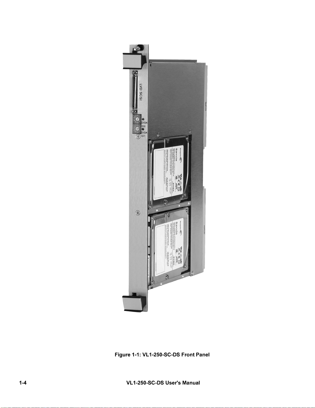
Figure 1-1 VL1-250-SC-DS Front Panel 1-4

Chapter 1
Manual Organization
and Introduction

This page intentionally left blank.

Scope
This chapter describes the organization of this manual and gives an overview of the VL1-250-SC-DS.
Manual Organization
This manual is organized as follows:
Chapter 1 MANUAL ORGANIZATION AND INTRODUCTION
Contains an overview of the manual organization and provides a brief product description.
Chapter 2 FEATURES AND SPECIFICATIONS
Describes the product features, compatibility, and electrical specifications.
Chapter 3 CONFIGURATION, INSTALLATION AND OPERATION
Provides information on how to configure and install the VL1-250-SC-DS .
Chapter 4 SCSI HARD DISK DETAILS
Contains specific details about the hard disk drive used on the VL1-250-SC-DS .
Chapter 5 PRODUCT SUPPORT, SERVICE AND WARRANTY
Describes what to do if you have trouble and how we will support you.
VL1-250-SC-DS Introduction
The VL1-250-SC-DS has been designed to provide a complete disk drive subsystem which is mechanically compatible
with the VMEbus. It has been designed specifically to interface with VMEbus processors with an embedded Ultra 320
SCSI Host Adapter. Together with the processor, a complete system can be installed in only two standard VMEbus sys-
tem slots. The VL1-250-SC-DS provides one or two hard disk drives within the same module making it very convenient
to have fixed data storage. The drives used on board the VL1-250-SC-DS were chosen for their compatibility, rugged-
ness and reliability. The Ultra 320 SCSI bus can be connected to the module via the front panel 68 pin Wide SCSI
VHDCI connector or via the P2 connector.
Manual Organization and Introduction 1-3


Chapter 2
Features and
Specifications

This page intentionally left blank.

Scope
This chapter describes the overall features and specifications of the VL1-250-SC-DS .
Features
The VL1-250-SC-DS incorporates one or two very compact winchester disk drives within a single module. The hard
disk drive(s) is a high-performance winchester type with embedded disk drive control electronics. This microprocessor
controlled embedded controller is on the hard disk and is compatible with ANSI X3.131-1986 SCSI commands. The
hard drive is a very high performer, with a 1-to-1 interleave and an average track-to-track access times of 10 millisec-
onds or less. It incorporates an embedded at least 8 megabytes of cache buffer which is operated in “look ahead”
mode, providing buffering for sequential sector operations. The hard drive(s) has been carefully packaged with suitable
control cables and power distribution connectors for direct attachment to single board computers in the VME chassis or
to external devices.
Ultra 320 SCSI Interface Description
In order to provide a method of embedding the disk drive control electronics within the hard disk drive, several disk
drive manufacturers jointly defined an interface specification. This specification for the Small Computer System Inter-
face has become known throughout the industry as “SCSI”. Basically, the SCSI interface consists of the required
address, data and control signals from a wide SCSI Host Adapter. Since a goal of the specification is to allow the disk
drive to be connected via standard cable, the specification required buffering of all signals so that the drive could be
mounted a suitable distance from the board interface. This distance, however, is limited to twelve meters. The specifi-
cation provides all signals via a 68-pin header connector for use with standard 68 conductor ribbon cable and connec-
tors. Table 2-2 is a description of the Ultra320 SCSI pin definitions. The direction indicated is relative to the host.
Pin Signal Pin Signal Direction Description
1 +DB(12) 35 -DB (12) In/Out Bidirectional data line 12
2 +DB(13) 36 -DB (13) In/Out Bidirectional data line 13
3 +DB(14) 37 -DB (14) In/Out Bidirectional data line 14
4 +DB(15) 38 -DB (15) In/Out Bidirectional data line 15
5 +DB(P1) 39 -DB (P1) In/Out Bidirectional data line parity1
6 +DB(0) 40 -DB (0) In/Out Bidirectional data line 0
7 +DB(1) 41 -DB (1) In/Out Bidirectional data line 1
8 +DB(2) 42 -DB (2) In/Out Bidirectional data line 2
9 +DB(3) 43 -DB (3) I n/Out Bidirectional data line 3
10 +DB(4) 44 -DB (4) In/Out Bidirectional data line 4
11 +DB(5) 45 -DB (5) In/Out Bidirectional data line 5
12 +DB(6) 46 -DB (6) In/Out Bidirectional data line 6
13 +DB(7) 47 -DB (7) In/Out Bidirectional data line 7
14 +DB(P) 48 -DB (P) I n/Out Bidirectional data line parity
15 GND 49 GND - Ground reference
16 DIFFSENS 50 GND - SCSI Sense/Ground reference
17 TERMPWR 51 TERMPWR - Terminator Power
18 TERMPWR 52 TERMPWR - Terminator Power
19 RESERVED 53 RESERVED - Reserved for future use
20 GND 54 GND - Ground reference
21 +ATN 55 -ATN In/Out Attention
22 GND 56 GND - Ground reference
23 +BSY 57 -BSY In/Out Busy
24 +ACK 58 -ACK - In Acknowledge
25 +RST 59 -RST In Reset
26 +MSG 60 -MSG Out Message
27 +SEL 61 -SEL In/Out Select
28 +C/D 62 -C/D Out Control/Data
29 +REQ 63 -REQ Out Request
30 +I/O 64 -I/O Out Input/Output
31 +DB(8) 65 -DB (8) In/Out Bidirectional data line 8
32 +DB(9) 66 -DB (9) In/Out Bidirectional data line 9
33 +DB(10) 67 -DB (10) In/Out Bidirectional data line 10
34 +DB(11) 68 -DB (11) In/Out Bidirectional data line 11
Table 2-2: SCSI Pin Definition
NOTES:
(1) The minus sign next to the signals indicates active low.
Features and Specifications 2-3

VL1-250-SC-DS Specifications
The following table provides the specifications of the complete VL1-250-SC-DS . Individual disk drive specifications are
given in their respective chapters.
General
Model: VL1-250-SC-DS
Description: Hard disk drive module compatible with Ultra 320 SCSI commands.
Interface: Ultra 320 SCSI
Drive Type: Particular type depends on capacity ordered. See Chapter 4 for drive
details.
Hardware Compatibility:VMEbus Double Eurocard (6Ux4HP)
Electrical
Power: +5VDC 0.110A(max)
+12VDC (Applicable to mounted devices only))
Physical
Size: 160mm x 234mm (Double Eurocard)
4HP (1 Standard Slots)
Construction: Double-sided FR4 PCB and steel chassis
Environmental
Temperature: 5-55oC Inlet Air (Operating)
-20 to 60oC (Non-operating)
Humidity: 8-90% RH, Non-condensing
Shock: Unit will withstand shock exceeding the specifications of
devices mounted)
Features and Specifications2-4

Features and Specifications 2-5
P2 Connector Pin Definitions
Ultra 320 SCSI
P2 Pin P2 SIGNAL P2 Signal P2 Pin
A1 +DB11 -DB 11 C1
A2 +DB10 -DB 10 C2
A3 +DB9 -DB 9 C3
A4 +DB8 -DB 8 C4
A5 +I/O -I/O C5
A6 +REQ -REQ C6
A7 +C/D -C/D C7
A8 +SEL -SEL C8
A9 +MSG -MSG C9
A10 +RST -RST C10
A11 +ACK -ACK C11
A12 +BSY -BSY C12
A13 GROUND GROUND C13
A14 +ATN -ATN C14
A15 GROUND GROUND C15
A16 TERMPOWER TERMPOWER C16
A17 DIFFSENS DIFFSENS C17
A18 +DBP -DBP C18
A19 +DB7 -DB7 C19
A20 +DB6 -DB6 C20
A21 +DB5 -DB5 C21
A22 +DB4 -DB4 C22
A23 +DB3 -DB3 C23
A24 +DB2 -DB2 C24
A25 +DB1 -DB1 C25
A26 +DB0 -DB0 C26
A27 +DBP1 -DBP1 C27
A28 +DB15 -DB15 C28
A29 +DB14 -DB14 C29
A30 +DB13 -DB13 C30
A31 +DB12 -DB12 C31
A32 GROUND GROUND C32
Table 2-3 P2 Pin Definitions

Chapter 3
Configuration, Installation,
and Operation

This page intentionally left blank.

Scope
This chapter describes how to configure, install and operate the VL1-250-SC-DS mass storage subsystem module.
Drive Hardware Configuration
The drives on the VL1-250-SC-DS can be configured for normal operation as SCSI units 0-15 by setting the front panel
switches with a small screwdriver.(See Figure 1-1) The particular configuration of the Unit ID's required depends upon
the software and the application operating system.
Hard Disk Drive Hardware Configuration
The hard drive can be set so that it is activated by the SCSI unit 0-15 ID, as is required to maintain compatibility with the
SCSI software. The hard drive installed on the VL1-250-SC-DS utilizes the Ultra 320 SCSI interface. It is possible to
connect other Ultra 320 SCSI devices via the interface cable and to connect 14 other units to the SCSI interface if need-
ed.
Considerations For Installation
There are several considerations before installing the VL1-250-SC-DS into your system.
VMEbus Slot Requirements
The VL1-250-SC-DS requires one slot in a standard VMEbus 6U card cage. Since there is drives are steel panel cover,
this could potentially cause a shorting problem. If you are going to have a VMEbus card located in the next adjacent slot,
you should carefully check it to make sure that no leads are likely to touch the VL1-250-SC-DS .
VMEbus Backplane Configuration
The VMEbus P1 connector supplies all operating power to the VL1-250-SC-DS and shunts the daisy-chain signals on the
P1 connector. However, no other VME signals are connected on board. Therefore, you must check your VMEbus back-
plane for all daisy-chain signals continuity at the two slot positions occupied by the VL1-250-SC-DS .
Power Supply Requirements
Make sure that your VMEbus power supply has adequate capabilities to support the operation of the VL1-250-SC-DS
when it is installed with all other cards in your VMEbus system. Pay particular attention to the +12 volt power require-
ment. The specifications listed in Chapters 2 and 4 should be consulted for the maximum current requirements. Your
power supply must be capable of providing sufficient current for the hard disk drive motor(s) to spin up during initial oper-
ation (approximately 5 seconds).
Installing the VL1-250-SC-DS
Make sure that all power is removed from the backplane before inserting the boards. Prior to inserting the VL1-250-SC-
DS into the card cage, it is necessary to verify the cable connections to the SCSI host/processor. Once you have con-
nected and properly seated the associated cable assemblies, you should insert the host/processor into the VMEbus card
cage. Now install the VL1-250-SC-DS into the VME chassis and mate the P1 connector properly. The P2 connector
should also be aligned. Then connect the VL1-250-SC-DS to the SCSI host/processor with a 68 pin Micro-D cable or via
the P2 connector on the backplane with the proper Phoenix International adapter module.
Configuration, Installation, and Operation 3-3

Drive Software Configuration
Initially you will need to run a device setup program in order to configure the software and hardware to properly recognize
the drives on the VL1-250-SC-DS . You should consult the host/processor manual and/or operating system manuals for a
description of the utility required to properly format and use your mass storage subsystem.
Hard Drive Software Configuration
The hard disk drive can be installed as SCSI unit 0-15. The disk drive characteristics are described in detail in Chapter 4.
It operates using the Ultra 320 SCSI interface and has to be configured by the host operating system software for proper
operation.
Terminator Power
Terminator power for the drives is routed via cable from the SCSI bus Host adapter. This supplies the Terminator Power
to the unit and the P2 connector pins for Terminator Power.(See Figure 1-2)
Termination
The active termination required for the SCSI-2 bus is on the VX2 module. The SensiTermTM circuitry will automatically
configure the termination for the SCSI bus. It determines if the SCSI bus signals are received from the P2 connector or
from the Micro-D connector on the front panel and sets the termination at the correct end of the SCSI bus. If the module
is in the middle of a SCSI bus route, the SensiTermTM circuitry automatically disables all on board termination.
Operation
Once the VL1-250-SC-DS has been configured properly and the software has been set up, operation is identical to that
of a standard SCSI storage subsystem. No specialized software is required.
Configuration, Installation, and Operation3-4

Chapter 4
ST973401LC Hard Disk
Drive
Details

Scope
This chapter describes the Seagate ST973401LC disk drive in detail.
Introduction
The ST973401LC is a high performance 2.5" one half inch high 73.4 gigabyte (formatted) disk drive with a 4.7
millisecond average seek time that is designed to operate with a SCSI host adapter or equivalent. The drive
features low power requirements and high shock resistance, enabling operation in portable environments. The
drive uses the industry standard Small Computer System Interface (SCSI-2).
Key Features
• Low power requirements enabling operation in portable applications
• High performance balanced low mass rotary voice coil actuator
• High shock resistance
• Dynamic spindle brake
• 8 Mbyte multisegmented, read look-ahead cache buffer
• Automatic error correction and retries
• Integrated SCSI controller
• Selectable sector sizes from 512 to 528 bytes/sector in multiples of 2 bytes/sector
• Embedded servo data rather than a separate servo data surface
Physical Configuration
Actuator Type: Balanced low mass rotary voice coil
Media Type: Thin Film
Recording Method: EPR4 16/17
Number of Disks: 2
Data Surfaces: 4
Data Heads: 4
Tracks: 102,104
Cylinders: 51,052
Bytes per Block: 512-528 variable, 512 default
Sectors per Track: 703 at 512 bytes/sector
Formatted Capacity: 73.4 Gbytes
Drive Interface: SCSI Ultra320
Drive Performance
Average Latency: 3.00 ms
Average Access:
Read 4.7 ms
Write 5.1 ms
Single Track Seek:
Read 0.65 ms
Write 0.95 ms
Max Full Seek
Read 807 ms
Write 9.1 ms
Rotation Speed: 10,009
Internal Transfer Rate: 506 to 753 mbits/sec (variable with zone)
External Transfer Rate: 5 - 80 Mbyte/sec (synchronous)
Cache Buffer Size: 8 Mbyte
ST973401LC Hard Disk Drive Details 4-3

4-4 ST973401LC Hard Disk Drive Details
Power Requirements
+ 12 Volt Start-up: 1.58 Amps (Maximum)
+ 12 Volt Typical: 0.19 Amps
+ 5 Volt Start-up: 0.70 Amps
+ 5 Volt Typical: 0.51 Amps
Typical Usage: 4.83 Watts
Physical Characteristics
Height: 1.62 inches
Length: 5.75 inches
Width: 4.00 inches
Weight: 2.20 pounds
Environmental Characteristics
Temperature: 5ºC to 55ºC (operating)
-40ºC to +70ºC (non operating)
Thermal Gradient: 20ºC per hour maximum
Humidity: 5% to 95% non-condensing
Altitude: -1,000 to 10,000 feet (operating)
-1,000 to 40,000 feet (non-operating)
Reliability
MTBF: 1,400,000 hours (POH)
MTTR: 10 minutes (typical)
Shock and Vibration
Shock: 15 G's (operating-normal)
40 G's (operating-abnormal)
maximum duration of 11 msec (half sinewave)
75 G's (non-operating)
maximum duration of 11 msec (half sinewave)
Vibration: 5-400 Hz @ 1.0 G (operating-normal)
5-22 Hz @ 0.020 inches
22-350 Hz @ 1.2 G's (operating-abnormal)
Functional Description
The ST973401LC contains all necessary mechanical and electronic parts to interpret control signals, position the
recording heads over the desired track, read and write data, and provide a contaminant free environment for the
heads and disks.
Power Connector
The ST973401LC has the DC power integrated into the 80 pin SCA interface connector.
Functional Description
The ST973401LC has a 80 pin SCSI connector. Two drives or other SCSI devices may be daisy chained together
with a maximum cable length of 18 feet, by using cabling that is compliant to SCSI specifications.
Table of contents
Other Phoenix International Storage manuals