W-IE-NE-R Plein & Baus GmbH 9 www.wiener-d.com
The MTCA Crate starts automatically after powering of the W-I
e
-N
e
-R MTCA.4 power supply.
Shortly after the W-I
e
-N
e
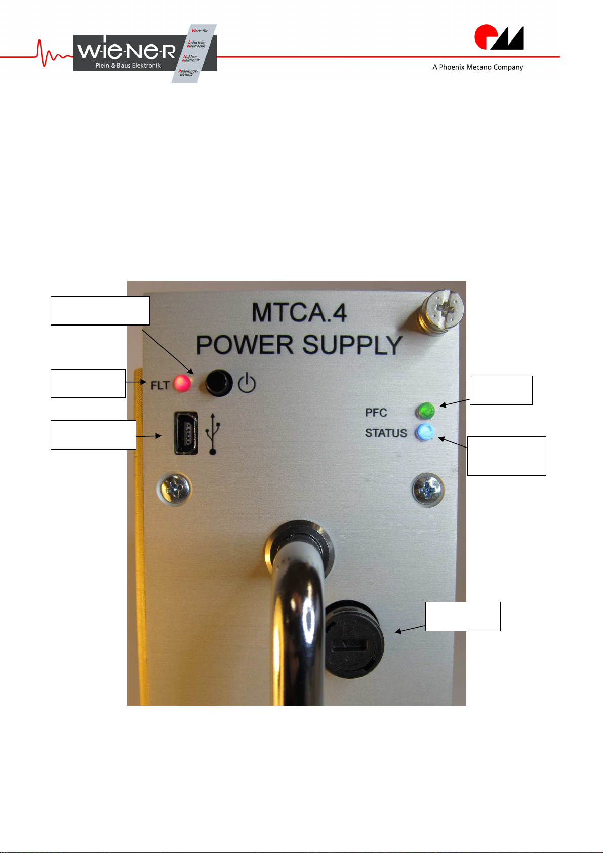
-R MTCA.4 power supply is at mains the PFC needs some seconds to
fill the capacitor banks while the green PFC LED shows a short fast blink, see fig 1. When fully
operational the PFC LED shows steady green state. If the PFC has any major problem it will show
it with special blinking codes (e.g. long-short-short) important for W-I
e
-N
e
-R repair workshop.
1
As specified in the PICMG MTCA.1 specification the crate starts first in autonomous mode with
both blowers (CUs, cooling units) on at maximum speed and the management hubs (MCHs) on.
After established communication with the power supply module (PM) the individual powers for
the attached AMC cards are distributed. If the calculated power budget is finished no further AMC
card will be integrated into the system. Finally the blowers speed down and up to a final optimum.
State-of-the-art to switch MTCA.4 crates ON and OFF regularly is to invoke it via one of the
MCHs command interfaces. Drawback is that the crate is not really OFF then: While all AMC
cards power down the CUs still work but at a minimum rate to cool the PM/s and the MCH/s. This
may be acceptable for a counting room but will not be silent enough for a laboratory.
Else if one likes to switch OFF the supply by hand W-I
e
-N
e
-R recommends to push the
◙
/ HSS
(Hot Swap Switch) only once, see fig. 1. (this default option can be inhibited by request, s. §5.6).
Then the W-I
e
-N
e
-R MTCA.4 will request the MTCA hub to power down the crate completely
controlled. After this interrogation the Status BLUE LED on the power supply front panel is
blinking till completely on signaling that this action has been finished. After this the W-I
e
-N
e
-R
MTCA.4 power supply is in the Hot Swap Status. The crate is then completely silent.
While in Hot Swap Status return the crate back into operation by one push on the
◙
/ HSS switch
– or – unplug the power cord or use an external circuit breaker to finally switch off the crate
– or – extract the module from one crate to another (with power cord on)
– or – move it to another power slot position (with power cord on).
W-I
e
-N
e
-R recommends not too often or regularly switch OFF the crates power supply by
– or – unplugging the power or power cord when just on substantial load,
– or – tearing the power supply out of the slot when just on substantial load,
even though the supply itself would not directly fear damage by doing this.
If more than one W-I
e
-N
e
-R MTCA.4 power supply resides in a crate switching on/off is more
complex if special redundancy conditions have to be met (1+1, or 2+0). All states following the
autonomous operation are controlled by the management work of an MCH. The MCH supported
redundancy setups will depend on the last or actual backplanes EEPROM configuration (FRU
settings) as well as on the geographical addresses under which the power supplies reside.
For state-of-the-art power redundancy and power sharing modes please refer to the MTCA.1
specification standard or request help from your system partner (e.g. N.A.T./ELMA/VadaTech).
FLT, see fig. 1, is signaling when power supply is a secondary power supply left without power in
a crate or blinking during firmware upgrade and if not of both signals for any reason of repair
and maintenance.
1
Within the newest versions of the W-I
e
-N
e
-R MTCA.4 power supply the PFC LED signals also the
redundancy level: off = inactive, green = active primary, orange = active secondary or redundant