Phoenix Mecano wiener PL508 User manual

Water Interconnection Revision
Service Manual

14. Dezember 2015 I W-IE-NE-R
General Remarks
The purpose of this manual is to describe the required procedure to complete the
modification of the power supplies water cooling system.
W-IE-NE-R revises this product and manual without notice. Differences of the
description in manual and product are possible.
With this service manual, the user received a specific training from a
W-IE-NE-R authority. Therefore the trained user himself received precautions and
advises to be aware for possible damage occurring during service. If any of the
revisions causes malfunction of one or more products, a regular RMA has to be
opened with W-IE-NE-R or its contractor.
Safety advises referring to W-IE-NE-R Power supplies will be made at the
beginning of the Manual. Each user has to follow additional safety advises of its
home institution. W-IE-NE-R assumes that only certified electricians with familiarity
of IEC 60364-4-41 (2005-12) or comparable rules to prevent electrical shocks will
do the service. In any case, W-IE-NE-R is not responsible for direct or indirect
influences of health of human beings.
Products mentioned in this manual are mentioned for identification purposes only.
Product names appearing in this manual may or may not be registered trademarks
or copyrights of their respective companies.
No part of this manual may be reproduced, transmitted, transcribed, stored in a
retrieval system, or translated into any language in any form by any means without
the express written permission of W-IE-NE-R.
In case of questions or problems don’t hesitate to contact our contractor
Magentasys, they my assist you or forward your concerns.
They’re located in 13/R-023 at Cern
W-IE-NE-R Plein & Baus GmbH
Linde 18
51399 Burscheid
Germany
+49 2174 678 0
info@wiener-d.com
MagentaSys
15, chemin de Sous-la-Ville
1272 Genolier
Switzerland
+41 22 366 33 33
info@magentasys.com

14. Dezember 2015 II W-IE-NE-R
Field of Application
This manual was made for one specific reason. – The revision of water
interconnections of W-IE-NE-R Power supply Units. Analogue given advises may
or may not correspond to other work steps given in other service manuals.
W-IE-NE-R does not recommend trying repair attempts to defective units
depending on advises given in this manual. W-IE-NE-R excludes completely any
liability for loss of profits, loss of business, loss of use or data, interrupt of
business, or for indirect, special incidental, or consequential damages of any kind,
even if W-IE-NE-R has been advises of the possibility of such damages arising
from any defect or error in this manual.
W-IE-NE-R gives a qualified training using a customer given selection of power
supplies instead. In case of issues / questions during the modification, please
contact our support.
Part number ranges of power supplies considered in this Manual:
0M02.xxxx, 0M05.xxxx, 0M21.xxxx, 0M22.xxxx, 0M24.xxxx
0P17.xxxx / 0P47.xxx
Further also referred to as PL508, PL512, Power-Supply or Maraton
according to CERN Database

14. Dezember 2015 III W-IE-NE-R
TABLE OF CONTENTS
1. Safety advice................................................................................................... 1
1.1. Charged Capacitors and Discharging........................................................ 1
1.2. Weight and Lever ...................................................................................... 1
1.3. Attention and awareness........................................................................... 1
1.4. General safety of electrical devices........................................................... 1
1.5. Functionality .............................................................................................. 1
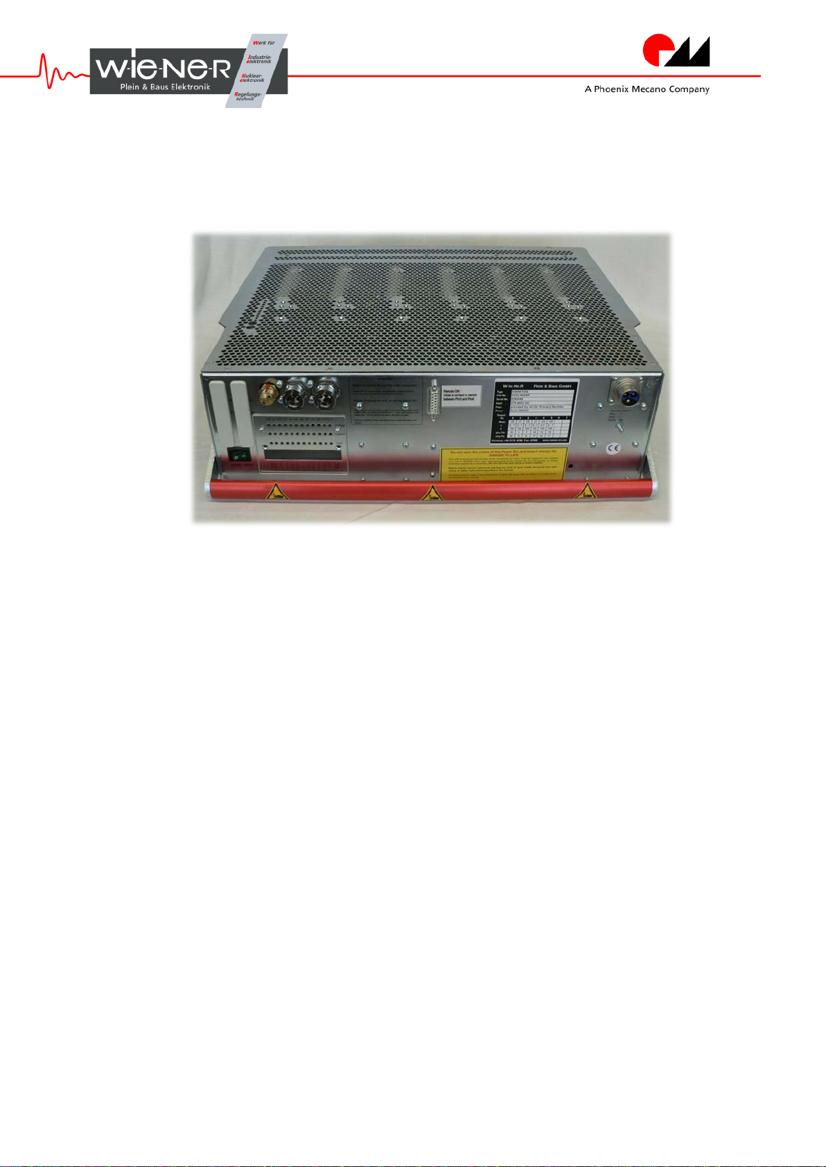
1.6. Unit identification....................................................................................... 1
2. What to Do and Why ....................................................................................... 2
2.1. PL 5xx / Maraton – Watercooled ............................................................... 2
3. Preparations.................................................................................................... 3
3.1. Check for damage..................................................................................... 3
3.2. Purge......................................................................................................... 3
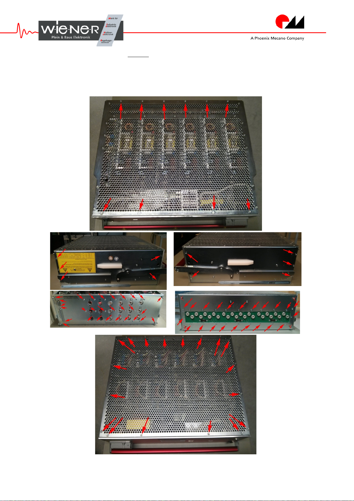
4. Opening the Power supply .............................................................................. 3
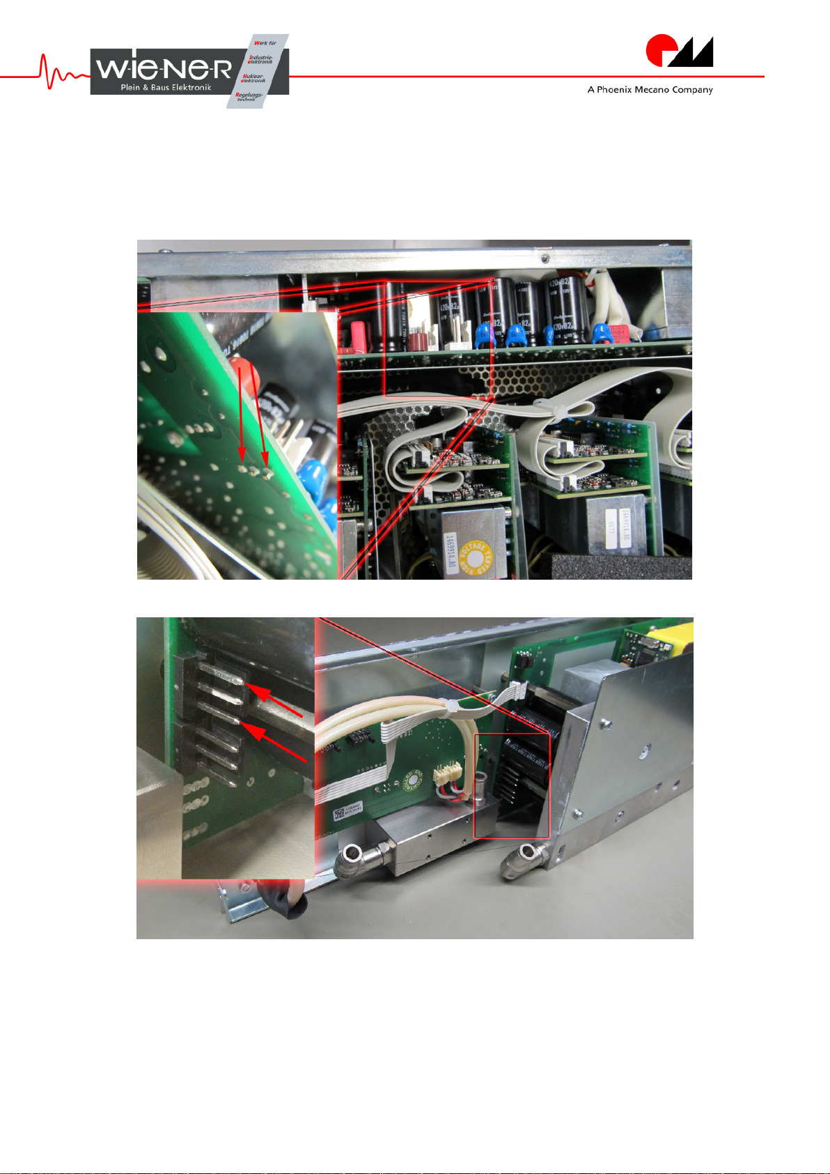
4.1. Capacitor Discharge.................................................................................. 5
4.2. Access to the Interior................................................................................. 6
4.3. Hints .......................................................................................................... 6
5. Modification..................................................................................................... 7
5.1. Main Differences between Units................................................................ 7
5.1.1.Standard Units („PFC“).............................................................................. 8
Front cover removal PFC...............................................................................9
5.1.2.Radiation Hard Units („MNE“).................................................................. 10
Front cover removal MNE............................................................................11
Backside access...........................................................................................11
5.2. Amount of Modules.................................................................................. 12
5.3. Age of Units / Different Tubing................................................................. 12
5.4. The Connector Block............................................................................... 13
Dismounting of Connector Block................................................................13
5.5. PFC Modification..................................................................................... 14
5.6. The Legris Tube ...................................................................................... 15
Cutting & Marking...........................................................................................15
Bending Radius / kinking................................................................................15
Plug & Unplug.................................................................................................16
Tube Circuitry / Typical Lengths.....................................................................16
6. Checkup, Front and Rear closing.................................................................. 17
7. Closing the Power supply.............................................................................. 19

14. Dezember 2015 IV W-IE-NE-R
8. Electrical tests ............................................................................................... 21
9. Leakage Check (AIR).................................................................................... 19
9.1. Check Procedure..................................................................................... 20
10. Pressure Test (Water)................................................................................... 20
10.1. Check Procedure..................................................................................... 20
11. Appendix ....................................................................................................... 21
11.1. List of Recommended Tools / Environment............................................. 22
11.2. Tubing examples (with water flow direction)............................................ 23
11.3. Pressure / Purge Environment Sketch..................................................... 24

14. Dezember 2015 1 Water Interconnection Revision
1. SAFETY ADVICE
The modification of Wiener power supplies, especially the work inside of them
requires a high level of attention. Further in this chapter, special advises should
extend the given state of knowledge to personal safety.
1.1. CHARGED CAPACITORS AND DISCHARGING
W-IE-NE-R Power supplies use an internal Voltage of 385VDC including
capacitors charged to this level. It is strongly recommended to use a
discharge resistor. How to identify the correct points to discharge and the
recommended resistor will be explained in chapter 4.1.
1.2. WEIGHT AND LEVER
The power supplies included in this revision are provided with a red lever.
This lever is designed to engage the units into the power bin, be careful not
to pinch your fingers.
Don’t underestimate the weight of the power supply units. Especially the
Magnetic Tolerant types contain iron shielding and weigh up to 30kg per
unit. Please follow general safety rules for proper handling bigger amounts
of heavy objects, available at your institutions safety advisor.
1.3. ATTENTION AND AWARENESS
Keep in mind that you want to improve running systems. Not to destroy
them. Therefore please raise awareness and attention while performing the
necessary steps advised by W-IE-NE-R employees and this manual.
1.4. GENERAL SAFETY OF ELECTRICAL DEVICES
Please note that this manual does not disable the electrical safety rules.
After modification, each unit has to be tested for electrical safety.
1.5. FUNCTIONALITY
A complete functional test before and after modification is highly
recommended to prevent damage on the unit or its environment.
1.6. UNIT IDENTIFICATION
It is highly recommended to mark the modified units. This prevents double
work. Please get in contact with PH-ESE for a unified marking and
database management.

14. Dezember 2015 2 Water Interconnection Revision
2. WHAT TO DO AND WHY
Now, that you are ready to begin the modification, it‘s the right moment to
hesitate and think about what you’ll do in the next time while following this
manual.
2.1. PL 5XX /MARATON –WATERCOOLED
W-IE-NE-R delivered a vast amount of watercooled power supplies to
CERN in the last decade. There are about 40 different units in use, a
complete amount of over 500 power supplies. They differ from each other in
many aspects depending on the experiments and collaborations. The
important differences will be explained later at 5.1. After longer operating
times it turned out that the build in water connectors get in trouble with
electrochemical corrosion. This caused leakage and damage in the past.
Therefore it is important to replace the old interconnections with new ones,
made out of stainless steel, capable of running over a long period without
problems. Further analyses of those issues are available at Vincent Bobilier
in the PH-ESE group.
Analysis figured out, that the main problem consists of 90° angled
connectors, at least 2 are used in every unit. According the named analyses
W-IE-NE-R supplies prepared and tested connection blocks, Legris tubes
and tools for tubing application as seen at chapter 5.6 .They will be
available in the PH-ESE group. This manual will show up how to exchange
those Blocks.

14. Dezember 2015 3 Water Interconnection Revision
3. PREPARATIONS
Before you can start, it is important to prepare your workspace. You’ll need
a stable, rugged surface with enough space for about 2x2 power supplies to
get best possible access. We recommend prefer plastics instead of wooden
surfaces due to possible abrasion. A complete list of tools / environment will
be given in chapter 11.1.
3.1. CHECK FOR DAMAGE
At first ensure that you have a functional and fully operational unit in front of
you. W-IE-NE-R recommends for this type of modification to refuse work on
obviously damaged units. Those should be declared for RMA to ensure
proper maintenance. To have a better approach of view if the unit doesn’t
work after modification, we recommend performing a functional test before
and after modification.
3.2. PURGE
Before opening the Power supply it is important to purge out all remaining
Water. Therefore connect a sufficient air supply with about 7bar to one of
the CPC Connectors (further CPC). Then use an open end CPC (or open
the external Valve if present) on the other Terminal. A connected tube
would be strongly recommended to dump the water where you want. Slowly
open the air supply, be aware that the connected Tube may swing around
when opening to fast! When the water is dumped, wait for about 5-10
seconds until the vapor fog disappears.
Please see chapter 11.3 for an Idea how to set up your environment.
If available, use oil filters for your air supply. Unless the amount of oil in the
pressure air system is small it could be better if you are in worry about your
cooling water cirquitry. See chapter 5.6 for further information about the
Tube.
DO NOT CHANGE THE PRESSURE RLIEF VALVE SETTING!
4. OPENING THE POWER SUPPLY
General precautions should be followed to improve the Quality of work.
We recommend to:
•Use a separate box for each screw type used in the power supplies,
also differentiate the lengths
•Clean the screw head from abrasion if needed before untighten it
•Don’t touch the interior before discharging.
•Please differ in loosening and removal of screws as told further. It
may save the units - and maybe your own health, too!
At first, remove the screws as seen in the uppermost Image, (referring to
chapter 5.3 you might ignore the back cover) and flip the unit upside down

14. Dezember 2015 4 Water Interconnection Revision
to begin with loosen the marked screws. Yet, it might be better not to
remove all screws, just let some in to hold the parts in place.
Only the red handle on the front and the bottom cover should be removed
now.

14. Dezember 2015 5 Water Interconnection Revision
4.1. CAPACITOR DISCHARGE
Discharge the capacitors by connecting two 10W / 47ΩResistors parallel to
the terminals as shown in the pictures. You may get better access by
removing the screws holding the front cover.
MNE
PFC

14. Dezember 2015 6 Water Interconnection Revision
4.2. ACCESS TO THE INTERIOR
After discharging, now it is safe to access the interior. All further advises
may differ in two major ways, depending on the type of power supply. This
will be explained at chapter 5.
4.3. HINTS
From experience there are some points you should know and follow by
opening the power supplies.
•There are two fixed thread-bolts on
each side which could damage wires
or block PCBs by removing the front
cover.
In some cases, you have to pay big
attention to your flat cables as seen
on the picture
•Pay attention to the ON/OFF Switch
wiring. There are
two ways it is
plugged onto the control units PCB,
depending on the control unit.
Unfortunately there is no housing.
And, for an unexperienced person,
no easy way to figure out wich control
unit is present.
Therefore, save the correct position
of each unit
s plug with a marker,
photo or something else. If you put it
in the wrong way, nothing will get
damaged, but the unit won’t turn on.

14. Dezember 2015 7 Water Interconnection Revision
•During the training, there were some
ci
rcumstances with prototypes of
m
araton units. The interieur made the
common way
in this manual nearly
impossible. In this case it figured out
to be better open the units from the
t
op. So, the opening procedure is
different, but the r
eplacement of
connector blocks and t
ubing stays
the same, altough ist more difficult
not to damage something.
5. MODIFICATION
Here we are. The Unit is purged, opened and discharged, as told before.
There are two major differences between the W-IE-NE-R watercooled
power supply units. It is important to know which type of unit you see in
Front of you to perform the correct further steps.
The amount of modules has nothing to do with the revision of the
connection block directly, but with the tubes length. There will be an
introduction into the identification and typical tubing of a power supply in
chapter 5.3, there you’ll also get an introduction into different tubing in older
units, even you might have not such big amounts of them.
The more you know, the better you can accomplish.
5.1. MAIN DIFFERENCES BETWEEN UNITS
The two types differ in their internal functions, output voltage and current
adjustments, wiring and unfortunately you can’t make out those features
yet. But this is not necessary for the modification. Important is to differ
between the two main variants, the MNE types and the PFC types. So you
can recognize the input modules as seen in 5.1.1 / 5.1.1 at best to know
what kind of unit you have.

14. Dezember 2015 8 Water Interconnection Revision
5.1.1. STANDARD UNITS („PFC“)
As seen on the picture, this is a standard watercooled power supply.
Best Part to see this is the PFC (Power Factor Correction) Module,
clearly to identify with the big storage choke. Additional to new tubes
(chapter 5.6) and the connector block (chapter 5.4) there has to be
made an additional modification on the PFCs heat exchanger, as
described in chapter 5.4
Replace the connector block at first, and then replace the fittings of
the PFCs heat exchanger. In the other way it won’t be possible to
remount the connector block.
Typical water flow - PFC

14. Dezember 2015 9 Water Interconnection Revision
FRONT COVER REMOVAL PFC
The best way of front cover removal is done by carefully opening it
like a door as seen on the picture. After removing all screws, first
unplug both tubes leading to the modules, they are the most
obstructing parts. Also, unplug the 385VDC cable from the PFC, the
switch connection to the control module or the flat wires to the
ethernet-unit only if needed. In every case take care to plug each
cable were it was – especially take care of the flat cables, there are
two identical connectors near each other. Heavy damage to the unit
may occur if they are not plugged properly.
Now, no further cables should be removed - you gained access to all
necessary Parts.

14. Dezember 2015 10 Water Interconnection Revision
5.1.2. RADIATION HARD UNITS („MNE“)
The radiation hard units, or “Maraton” (Magnetic and Radiation
Tolerant New Power supply System) can be identified with the big
mains input module, the MNE ([Ger.] Modul Netz Eingang) here the
tubing (chapter 5.6) and the connector block (chapter 5.4) have to be
revisioned. The MNE, instead of the PFC, has no heat exchanger.
Only its rectifier (chapter 5.4) should be recognized.
Typical water flow - MNE

14. Dezember 2015 11 Water Interconnection Revision
FRONT COVER REMOVAL MNE
Similar to the PFC type, the best way
of front cover removal is done by
carefully opening it like a door. At first,
additionally remove the screws and
bolts as seen on the picture. Loctite
242 was used during production
process, usage is recommended for
remounting following the replacement
work. After the removal of those crews,
first pull out the front cover on the right
side, slide a little bit to the right and at
least the left side and pay attention to
the fixed bolts as seen in chapter 4.3. Now you may remove the
385VDC plug from the MNE if necessary. Proceed with removing the
Connector block.
Now, no further cables should be removed - you gained access to all
necessary parts.
BACKSIDE ACCESS
Almost similar is access you have to get to the units backside (with the
Power connectors) therefore remove the three screws on each side and the
marked screws / bolts (4,5mm wrench size) as seen on the pictures below.
Important to know is, that you loosen the carrier PCB of the power contacts,
to remove the back cover only. DO NOT DISMOUNT the wiring, it is
tightened with a torque wrench and each of the 40 units may differ
tremendous in this particular part. Even there are more screws to remove
its way much safer to gain access with this method.

14. Dezember 2015 12 Water Interconnection Revision
5.2. AMOUNT OF MODULES
At Cern, according to the PH-ESE database, most watercooled Power
supplies are fully equipped with 6 Modules. Each module fewer, the part
number varies corresponding.
Example: 0M21.0102L 6 Modules
0M22.2004L-2 6-2 4 Modules
5.3. AGE OF UNITS /DIFFERENT TUBING
Since approximately 2006 we use the common Module heat exchanger with
both fittings on the back. Before 2006 there were used different types of
exchangers, equipped with connectors on the front and back side of the
modules. So, in appendix 11.2, you’ll find examples to get an idea how the
tubing is realized. At older units, the tubing is a little bit more complicated
and involves the danger of closing dead circuits. Please be aware not doing
so.

14. Dezember 2015 13 Water Interconnection Revision
5.4. THE CONNECTOR BLOCK
0M4S.0000
0M4S.0001
Pretested and Ready-to-Mount units as seen on the picture will be delivered
from W-IE-NE-R. They are equipped with a pressure relief valve adjusted to
blow off at 16−0
+1 bar. There are two different Parts available, 0M4S.0000,
0M4S.0001, only differing in dimensions - not in function.
DISMOUNTING OF CONNECTOR BLOCK
Dismount by removing the Tubes and screws (as described in chapter 5.6).
The rectifier (if present -> MNE – types only) as seen on the picture below
should be removed after loosening the block. Pay attention to preserve the
aluminum rectifier adaption including the screws.
Be careful, depending on the type of power supply there are sensitive wires
and PCBs around the block. The positioning of cables may vary – so lay
back each cable where it was, maybe make a backup for yourselves by
taking a picture to compare before and after.
In some cases there is a PCB, carrying 36 potentiometers, present. It might
be easier to remove this PCB from the front cover.

14. Dezember 2015 14 Water Interconnection Revision
Reassemble by first attaching the rectifier (if present) including the
adaption. Don’t forget to apply heat conducting paste at this point. A new
M5 spring washer is recommended if the old one seem worn out. Finally
tighten the block to the front cover.
5.5. PFC MODIFICATION
If you have a PFC equipped unit, you also may exchange both Legris
fittings. They have to be the 90° angled versions. Use a 13mm wrench to
loosen and remove them, dry-clean the thread with a pipe brush or similar
and tighten the new one with 6.5Nm Torque.
Use no lubricant or thread sealant.

14. Dezember 2015 15 Water Interconnection Revision
5.6. THE LEGRIS TUBE
For the internal tubing, we use a Legris Polyamide (PA) Tube. The cutting
and handling will be explained in this chapter. It is important that any
deformation of the tubes cross section or damage of the tube itself should
be prevented.
The Tube is resistant to the most common liquids (visit
https://www.parker.com) for further information about their Polyamide
tubes.)
CUTTING &MARKING
Always use the provided cutting tool and avoid deformation due a blunt tool. The
correct plug in depth of 17mm should be marked to identify a proper plug in.
BENDING RADIUS /KINKING
As said in the introdiction avoid kinking, and do not undercut the bending radius.
This manual suits for next models
1
Table of contents
Other Phoenix Mecano Power Supply manuals
Popular Power Supply manuals by other brands

Wisi
Wisi FLEXSWITCH DRP 1533 operating manual

Gallagher
Gallagher G36030 instructions

Gradus Group
Gradus Group SENAL PHANTOM PS-48B quick start guide

Moons'
Moons' Applied Motion Products PS480D72 quick start guide

MT Mustang Tattoo
MT Mustang Tattoo POWER EXPERT quick start guide

Epson
Epson S1F76640 Technical manual