PHONIC CORPORATION Page 9
MU1705 USER
’
S MANUAL
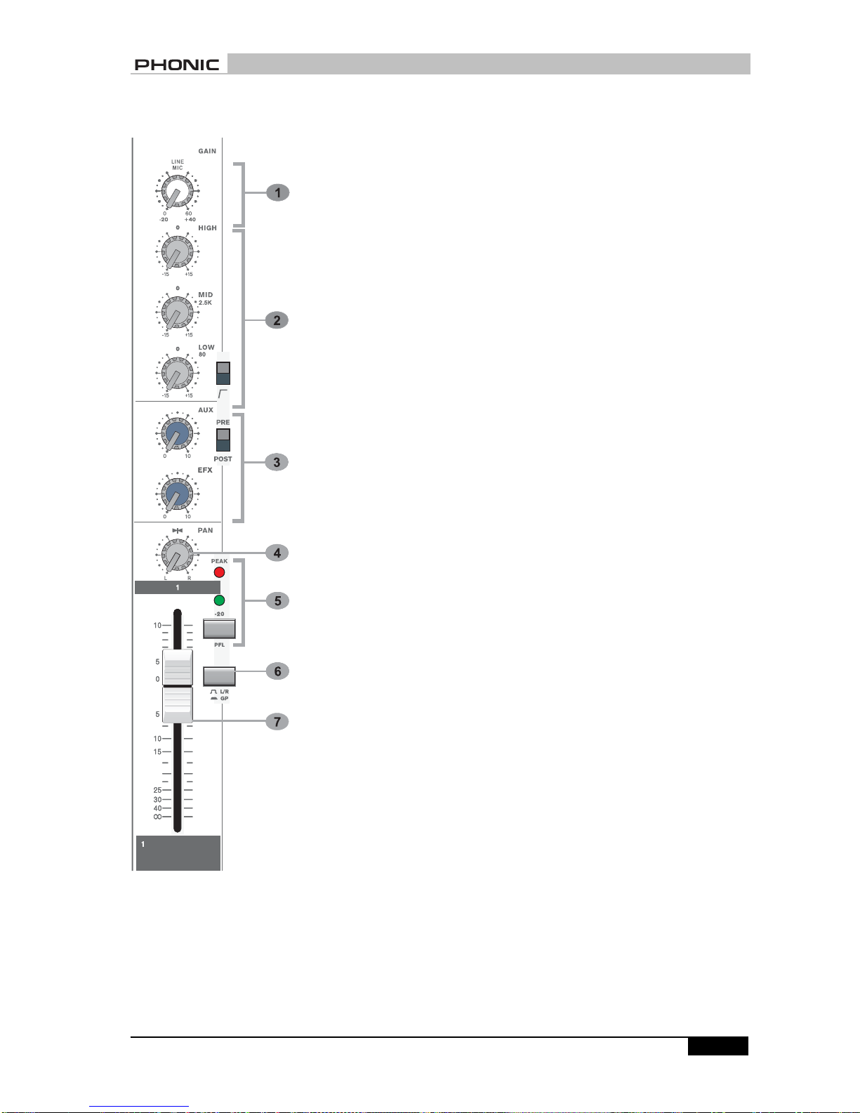
CHANNEL STRIP DESCRIPTION
Two inputs are available to the
mono input channel, via an XLR
connector (normally for micro-
phone sources) or a 3-pole 1/4”
phone jack for higher level signals
such as keyboards, drum ma-
chines, synths or tape machines.
Bothinputsocketsarepermanently
active, and may be used by sim-
ply plugging the source into the
required input. You do not need
to unplug something from the mic
socket if you want to use the line
input. When both the microphone
and line signals are plugged into
any channel from CH1 to CH5,
then the circuit will automatically
be switched to line source.
An unbalanced INSERT is offered
which is a break point in the input
channel signal path. It allows the
signal to be taken out of the mixer,
through an external device and
then brought back into the con-
sole to continue through to the
final output. The insert is a 3-pole
1/4” phone jack, which is normally
by-passed.
When a jack plug is inserted, the
signal path is broken at a point
just
after the high pass filter, but before
theEQsection.Thesignalfrom the
channel appears on the TIP of the
phone plug and is returned on
the RING. The insert point allows
compressors, limiters, effect and
other signal processing units to
be added as required to particular
input channels and because it is
located PRE EQ, noise generated
by the external equipment may be
1. GAIN
This rotary knob adjusts the channel
signal level. Too high, and the signal
willdistort as itoverloadsthe channel.
Too low, and the level of back hiss will
be more noticeable and you may not
be able to get a high enough signal
levelto the outputofthe mixer. Proper
gainorgain settings allow themixerto
workatthebestoperatinglevel.Adjust
thegainwhenthereis a signal present
to the highest level without triggering
the peak LED. That is the most ap-
propriate position.
This gain adjuster has two indications
to match either a microphone or line
inputsignal. When youuse the micro-
phoneinput, please referto the inside
ringfrom0~+60 dB; butwhenyou use
line input, please refer to the outside
ring from -20~+40dB.
Ifyouuseacondensormicrophone, it
isrequiredtosendphantompowerto
it. The global phantom power switch
is located on the rear panel.
All faders (Group 1, Group 2, Mono,
L/R and CH1~11) should be all the
way down when you switch on the
phantom power. In order to prevent
excessive noise to stage monitor
speakers and main speakers,
phantom powered mics should be
plugged in after the phantom power
is switched on.
2. EQUALIZERS
These equalizers are designed to
suit different room acoustics, control
feedback and improve the live PA
sound. No amount of equalization will
correct the frequency response curve
of a poor loudspeaker. Always begin
with all controls in the “0” position and
avoid excessively cutting/boosting
CHANNEL STRIP
DESCRIPTION