Phontech Communication 4000 User manual

PHONTECH
PHONTECH COMMUNICATION
P.B. 274, 3183 HORTEN NORWAY
PHONE +47 33 08 35 00 FAX +47 33 08 35 01
www.phontech.no
HANDBOOK
FOR
BATTERYLESS TELEPHONE SYSTEM 4000
(2000 GENERATION)
PHONTECH
Handbook rev. no.4
Oct.2004

BATTERYLESS TELEPHONE SYSTEM 4000
User Manual content
Document no.
Description Unit
type Page
(pdf) Page
Paper copy
N/A Handbook frontpage BTS-4000 1 1 of 1
N/A User Manual content BTS-4000 2 1 of 1
A-9292 DNV Type Approval Certificate BTS 4000 3 1 of 3
99400-000-DE System Description BTS-4000 4-17 1-14
99400-000-CO Commissioning procedure BTS-4000 18 1 of 1
99400-006-ML-01 Single line tlph. unit, - Flush mount 4050/4051 19 Annex A
99400-006-ML-02 Single line tlph. unit, - Flush mount 4050/4051 20 Annex B
99400-007-ML-01 Single line tlph. unit, - Wall mount 4050/4051 21 Annex C
99400-007-ML-02 Single line tlph. unit, - Wall mount 4050/4051 22 Annex D
99400-009-ML-01 12 line tlph. unit, - Flush mount 4060/4061 23 Annex E
99400-009-ML-02 12 line tlph. unit, - Flush mount 4060/4061 24 Annex F
99400-010-ML-01 12 line tlph. unit, - Wall mount 4060/4061 25 Annex G
99400-010-ML-02 12 line tlph. unit, - Wall mount 4060/4061 26 Annex H
99400-011-CD Relay module for tlph. units N/A 27 Annex I
99400-011-CA Relay module for tlph. units N/A 28 Annex J
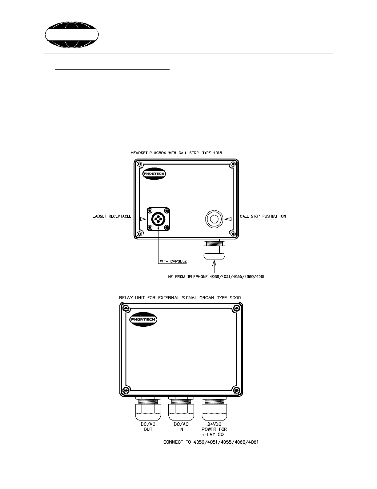
00400-002-ML Headset plugbox w/call stop 4018 29 Annex K
00400-002-IW Headset plugbox w/call stop 4018 30 Annex L
96900-000-ML Relay unit 9000 31 Annex M
96900-000-IW Relay unit 9000 32 Annex N
00900-002-ML Headset w/chest switch 9010 33 Annex O
96900-011-ML Headset plugbox 9011 34 Annex P
88000-005-ML Headset w/chest switch & plug 0018 35 Annex Q
88100-004-DE Alarm horn 1009 36 Annex R
N/A Rotating beacon R300/301 37 Annex S
99400-012-EC Single line tlph. unit, External connection 4050 38 Annex T
99400-013-EC Single line tlph. unit, External connection 4051 39 Annex U
99400-014-EC 12 line tlph. unit, External connection 4060 40 Annex V
99400-015-EC 12 line tlph. unit, External connection 4061 41 Annex W
99400-017-EC BTS 4000 – Single line system
External cabling BTS-4000 42 Annex X
99400-018-EC BTS 4000 – 12 line system
External cabling BTS-4000 43 Annex Y
Handbook page
2/43

Handbook page
3/43

Doc.No.: 99400-000-DE
01 18.01.2002 REVISION EM-904 TBA RS TBA
0 09.05.2001 FINAL DOCUMENTATION TLY TBA TLY
REV No: ISSUE DATE REASON FOR ISSUE PREPARED CHECKED APPROVED
This document is the property of PHONTECH and
must not be copied or shown to a third person
without our written acceptance. In the interest of
product improvement, PHONTECH reserves the
right to alter specification and design without
notice.
SIZE: A4 UED no: M002
DOC no: 99400-000-DE
TITLE:
BATTERYLESS TELEPHONE SYSTEM
DESCRIPTION
FILE NAME: 99400-000-DE
V:\prosjekt\SERIE\4\4050-51-56-57-60-61 fellesdokumenter\desc\99400-000-DE.doc Page 1of 14
PHONTECH
BATTERYLESS TELEPHONE SYSTEM 4000
SERIES 4050/4051/4055/4060/4061.
SYSTEM DESCRIPTION.
LIST OF CONTENTS: page
1. GENERAL DESCRIPTION 2
2. LIST OF TELEPHONE UNITS 3
3. ADDITIONAL EQUIPMENT 4
4. LIST OF FACILITIES 7
5. BASIC MEANS OF OPERATION 8
6. INSTALLATION 10
•SYSTEM CONFIGURATION
•MOUNTING
•CABLE TERMINATION
•CABLE REQUIREMENTS
•GLANDING
•SCREENING
•FERRULING
•MARKING
•FASTENING
•PRESERVATION
•VOLUME ADJUSTMENT
7. TECHNICAL DATA 12
8. SINGLE LINE DIAGRAM -12 LINE SYSTEM 13
9. SINGLE LINE DIAGRAM -SINGLE LINE SYSTEM 14
Handbook page
4/43

Doc.No.: 99400-000-DE
Page 2of 14
.
PHONTECH
1. GENERAL DESCRIPTION
The batteryless telephone system is developed and manufactured at phonTECH A/S.
The different modules in the system are designed to meet the need and demand for non-
powered internal communication on ships.
Basically the system is divided into two types, the single line system (4050/4051) for end-to
end communication between two stations, like the bridge and the machinery spaces.
The second type is the 12 lines system, (4060/4061) for up to 12 stations.
The 4055 type is a weatherproof telephone for rougher environments. Equipped with
weatherproof handset.
The compact design provides good installation possibilities, with a minimum space
requirement.
The flush mounting units are adapted to the DIN 144x144 standard for easy mounting in the
bridge and engine control consoles.
The modules may also be wall mounted; this requires a wall mounting back-box. (Optional)
The different units are prepared for gland mounting, i.e. holes have been fitted for a wide range
of cable glands.
Several additional types of equipment may be connected to the Batteryless Telephone System,
like headset connector boxes, extra headsets, power supplies, external signal devices relay
switch boxes, etc.
Handbook page
5/43

Doc.No.: 99400-000-DE
Page 3of 14
.
PHONTECH
2. LIST OF TELEPHONE UNITS
Type BTS 4061. 12 lines amplified battery’s telephone.
Type BTS 4060 12 lines battery’s telephone.
Type BTS 4051 Single line amplified battery’s telephone.
Type BTS 4050 Single line battery’s telephone.
Type BTS 4055 12 lines WP (weatherproof) telephone. Bulkhead mounting.
EXAMPLE: BTS 4060 -12 lines battery’s telephone.
PHONTECH
Handbook page
6/43

Doc.No.: 99400-000-DE
Page 4of 14
.
PHONTECH
3. ADDITIONAL EQUIPMENT.
Type 4018 Headset Plug-box with Call stop.
Type 9000 External signal device relay switchbox.
Type 0018 Headset with chest switch and plug.
Type 9010 Headset with chest switch.
Type 99400-011 Relay plug-in module for external signal device.
Type 4052 Junction box type I (12 ext.)
Type 4053 Junction box type II (8 ext.)
H E A D S E T
4018
STOP
CALL
9 0 0 0
Handbook page
7/43

Doc.No.: 99400-000-DE
Page 5of 14
.
PHONTECH
Handbook page
8/43

Doc.No.: 99400-000-DE
Page 6of 14
.
PHONTECH
RELAY MODULE (PCB 99400-011)
A relay module for activation of external signal device can be installed in the following units:
-4050 / 4051 / 4055 / 4060 / 4061
The relay module is to be mounted by the installer. The unit is delivered separately, and is to be
plugged into the appropriate telephone unit.
•Open the backbox on the telephone unit.
•Plug the relay unit into the receptacle on the PCB inside the telephone. Make sure the
connector pins make contact.
•Snap the stand off`s (2pcs) into the holes in the PCB.
•Make the connections according to the installation drawings 99400-017-EC or 99400-018-
EC.
•If DC voltage is used, make sure the polarity is correct. (Indication on the dwgs. 99400-
017-EC and 99400-018-EC)
Handbook page
9/43

Doc.No.: 99400-000-DE
Page 7of 14
.
PHONTECH
4. LIST OF FACILITIES.
•12 LINES BATTERYLESS TELEPHONE WITH AMPLIFIER 4061.
-Handset with PTT button.
-Noise cancelling microphone.
-Piezo -electric buzzer for call indication.
-Call led.
-20 seconds call delay timer. (24 VDC required)
-Call stop button.
-Call line rotary selector switch.
-Back lightning of the line selector and the call stop button. (24 VDC required)
-Extreme low current drain speech amplifier.
•12 LINES BATTERYLESS TELEPHONE 4060.
-Handset with PTT button.
-Noise cancelling microphone.
-Piezo-electric buzzer for call indication.
-Call led.
-20 seconds call delay timer. (24 VDC required)
-Call stop button.
-Call line rotary selector switch.
-Back lightning of the line selector and the call stop button. (24 VDC required)
•SINGLE LINE BATTERYLESS TELEPHONE WITH AMPLIFIER 4051.
-Handset with PTT button.
-Noise cancelling microphone.
-Piezo-electric buzzer for call indication.
-Call led.
-20 seconds call delay timer. (24 VDC required)
-Call stop button.
-Back lightning of the call stop button. (24 VDC required)
-Extreme low current drain speech amplifier.
•SINGLE LINE BATTERYLESS TELEPHONE 4050.
-Handset with PTT button.
-Noise cancelling microphone.
-Piezo-electric buzzer for call indication.
-Call led.
-20 seconds call delay timer. (24 VDC required)
-Call stop button.
-Back lightning of the call stop button. (24 VDC required)
Handbook page
10/43

Doc.No.: 99400-000-DE
Page 8of 14
.
PHONTECH
5. BASIC MEANS OF OPERATION.
•GENERAL
The batteryless telephone system is operated by means of the handset with PTT switch,
the call line selector switch, (4055/4061/4060 only) and the call generator crank.
There is no priority between units in the system and several users can join the system
simultaneously. All users will then join the same conversation.
The units are equipped with screw terminals for connection of a headset, phonTECH type 9010.
The below will give a brief description of how to operate the batteryless telephone system.
•MAKE A CALL TO ANOTHER STATION (4055/4061/4060)
1. Lift the handset. See sketch on page 9 for movement.
2. Select the line by means of the line selector.
3. Crank the generator 3-5 turns.
•ANSWER A CALL FROM ANOTHER STATION.
(ALL TYPES 4055/4061,4060,4051,4050)
1. Lift the handset (See sketch on page 9 for movement) and press the PTT button.
Keep the button pressed at all times during conversation.
2. Optional headset: Set the PTT switch to ON and answer the call.
3. NOTE: IF EXTERNAL POWER IS CONNECTED TO THE SYSTEM, THE CALL
DELAY TIMER WILL KEEP THE CALL LED ON THE TELEPHONE ILLUMINATED
FOR ABOUT 20 SECONDS. TO UNLIT THE LED, PRESS THE “CALL STOP”
BUTTON ON THE TELEPHONE, OR ON THE HEADSET PLUG-BOX 4018.
4. NOTE: IF EXTERNAL POWER IS CONNECTED TO THE SYSTEM, AND ANY
ADDITIONAL SIGNAL DEVICE IS CONNECTED TO THE TELEPHONE, THE CALL
DELAY TIMER WILL KEEP THE SIGNAL DEVICE ACTIVE FOR ABOUT 20
SECONDS. TO SILENT THE SIGNAL DEVICE, PRESS THE “CALL STOP” BUTTON
ON THE TELEPHONE, OR ON THE HEADSET PLUG-BOX TYPE 4018.
•TERMINATE A CONVERSATION. (ALL TYPES 4055/4061,4060,4051,4050)
1. Replace the handset in the holder. (See sketch on page 9 for movement)
2. On optional headset set the PTT switch on the chest-switch back to normal position.
•MAKE A CALL TO ANOTHER STATION ON SINGLE LINE SYSTEM
(4051/4050).
1. Lift the handset (See sketch on page 9 for movement) and press the PTT button. Keep the
button pressed at all times during conversation.
2. Crank the generator 3-5 turns.
Handbook page
11/43

Doc.No.: 99400-000-DE
Page 9of 14
.
PHONTECH
•Headset type 9010 -Operation
Make a call out from the telephone to another station:
1. Put the headset on, with the microphone close to your mouth.
2. Select line, operate the call crank on the telephone.
3. If / when the call is answered, set the talk -switch to on or temporary on. Keep the talk
switch operated at all times during conversation.
4. After the conversation, set the talk-switch back to off position.
Answer a call from another station:
1. Put the headset on, with the microphone close to your mouth.
2. Set the talk -switch to on or temporary on.
3. After the conversation, set the talk-switch back to off position.
Handbook page
12/43

Doc.No.: 99400-000-DE
Page 10 of 14
.
PHONTECH
6. INSTALLATION.
•SYSTEM CONFIGURATION:
The system is to be configured by the installer. Each telephone must be connected to
different “call number” with regards to the Line selector (rotary switch). This is done by
means of links in each telephone. The link is to be connected between terminal 13 and the
desired call number. (1-12)
Consult the installation drawing 99400-017-EC and 99400-018-EC for examples.
•MOUNTING:
The telephone units (all types) are delivered for flush mounting. Optional wall mounting boxes
are delivered upon request.
PhonTECH highly recommends the use of junction boxes for the external cable distribution.
The junction box must be located as close to the amplified telephone (4051/4061) unit as
possible.
On request PhonTECH will supply the junction box. Type 4052 and/or 4053.
The sub-units (9000/4018/) are delivered with wall mounting box as standard.
Ref. actual Data sheet for each unit and Technical specification for mounting details.
•COMPASS SAFE DISTANCE
Compass type Safe distance
BTS-4050/4051 / 4060/4061
Standard 1,7m
Steering
Stand by steering Emergency 0,95m
•CABLE TERMINATION.
All termination according to the External Cabling diagram (example) 99400-017/18-EC. In
most cases Phontech will supply a detailed custom designed “system cable diagram” for the
actual delivery.
•CABLE REQUIREMENTS.
All cables used with the Batteryless Telephone System to be of approved ship cable type.
ESPECIALLY IMPORTANT:
oCommon outer screen.
oIndividually twisted pairs.
Handbook page
13/43

Doc.No.: 99400-000-DE
Page 11 of 14
.
PHONTECH
oRecommended conductor area is 0.75 sq.mm.
oAll cabling in the batteryless telephone system to be a separate network.
oDO NOT COMBINE WITH OTHER CABLES. THIS IS TO PREVENT
DISTURBANCE AND NOISE CAUSED BY INTERFERENCE.
•GLANDING.
The cables enter the units by means of cable glands. Where cable glands are not supplied from
factory, the installer must adapt the glands to the actual cable outer diameter. This is to obtain
the specified ingress protection.
•SCREENING.
The cable screen must be terminated to the ships GND in the “main unit” (4051/4061). The
cable screen must be connected through the junction box(s) and terminated in terminal no 21 or
earth stud in all telephones . Ref. drawings 99400-017-EC or 99400-018-EC.
•FERRULING.
The conductors to be ferruled prior to termination onto the screw terminals.
•MARKING.
Each cable to be marked with cable number.
Each conductor to be marked with the specific termination number.
Please note that Phontech uses plug-able screw terminals as standard. This is to make the
installation and service work as smooth as possible.
•FASTENING.
Where applicable, the cables and the conductors shall be strapped to the structure.
•PRESERVATION.
Prior to, during, and after completion of the installation the equipment surfaces to be protected
against acid holding fluids, pollution, moist, impacts etc.
This in order to avoid damaged equipment for which Phontech will void warranty claims.
•VOLUME ADJUSTMENT
Common volume adjustment for the whole system may be adjusted inside BTS 4061 on the
circuit board, R13. Adjust to “proper”audio level in the “earpiece”during a normal
conversation.
Handbook page
14/43

Doc.No.: 99400-000-DE
Page 12 of 14
.
PHONTECH
7. TECHNICAL DATA. TELEPHONE UNITS 4050/4051/4060/4061
Dimensions flush mounting:
240 x 144 x 70 mm. (h x w x d)
Cut-out measurement flush mounting:
212 x 116 mm. (h x w)
Dimensions wall mounting wall mounting box included:
242 x 146 x 73 mm. (h x w x d)
Type 4050/51/60/61: add 78 mm to depth for handset.
Weight flush mounted: 1,4 kg.
Weight wall mounted: 1,8 kg.
Operation voltage 24 VDC (optional)
Ingress protection: IP 44.
Technical data for substations etc., see data sheets for each unit.
TECHNICAL DATA. WP TELEPHONE UNIT 4055.
Dimensions flush mounting:
240 x 144 x 70 mm. (h x w x d)
Cut-out measurement flush mounting:
212 x 116 mm. (h x w)
Dimensions wall mounting wall mounting box included:
242 x 146 x 73 mm. (h x w x d)
Type 4055: add 115 mm to depth for handset.
Weight flush mounted: 1,4 kg.
Weight wall mounted: 1,8 kg.
Operation voltage 24 VDC (optional)
Ingress protection: IP 44.
Handbook page
15/43

Doc.No.: 99400-000-DE
Page 13 of 14
.
PHONTECH
8. SINGEL LINE DIAGRAM –12 LINE SYSTEM
Handbook page
16/43

Doc.No.: 99400-000-DE
Page 14 of 14
.
PHONTECH
9. SINGEL LINE DIAGRAM –SINGLE LINE SYSTEM
Handbook page
17/43

COMMISSIONING PROCEDURE
Adresse: Page 1 of 1
Bromsveien 19, N-3183 Horten
Tlf.: +47 33083500 fax: 33083501
www.phontech.no V:\prosjekt\SERIE\4\4050-51-56-57-60-61
fellesdokumenter\doc\99400-000-CO.doc
PHONTECH
Use the tables below as guide during the commissioning of the batteryless telephone system.
Installation (site):__________________________________
Customer/ client:__________________________________
Hull / building no:__________________________________
SCOPE OF SUPPLY
Qty. Unit Type no. Serial no. Comments
COMMISSIONING TESTS
NO ACTION RESPONSE
(OK/FAILED) COMMENTS DATE DUE
FOR
CORRECTION
1 Check if the handbook is delivered
and available for commissioning.
2 Check the installation according to
installation instructions.
Ref, doc. 99400-000-DE
(Twisted pairs / screening)
3 Check call line assignment in
telephones: (Link n-13)
4 Check call signals and speech
communication in the hole system.
5 Check the additional signal devises
(if installed) is operating.
(20 sec. Timer)
Date:___________________
Customer / clients authorized representative signature:_______________________________
Phontechs representative signature: _______________________________
Handbook page
18/43

Handbook page
19/43

Handbook page
20/43
Table of contents
Popular Telephone manuals by other brands

Sirius XM RAdio
Sirius XM RAdio SXMTTR3 Installation & user guide

Yealink
Yealink T42S-Skype for Business quick start guide

PCS
PCS System 24/48 user guide

Siemens
Siemens Hicom 150 E Office operating instructions

Interquartz
Interquartz Basic Phone 98380 XWA operating instructions

BT
BT Revelation Owner's handbook