Photonic PL Series User manual

PL SERIES
OPERATING INSTRUCTION
ok_PL_BA_e_07 14.03.2007 22:55 Uhr Seite 1

1 Halogen lamp
2 Lamp socket
3 Lamp holder
4 Filter holder
5 Filter holder guide
6 Mechanical brightness control
(“B“-models)
7 See “12“, only with “B“ models
8 Cover with carrying handle
9 Light guide collet
10 Heat protection filter
11 Primary circuit fuse
12 On/off switch
+ electrical brightness control
13 Mains supply cable
14 Socket for mains plug
15 Fuse holder
16 Terminal strip for lamp socket
17 Locking button
18 Flip in filter (“F“-models)
19 Display (“D“-models)
20 Remote analog (“Ra“-models)
21 Remote RS232 (“Rs“-models)
ok_PL_BA_e_07 14.03.2007 22:55 Uhr Seite 2

Please read all the operating instructions before putting the cold-light source into operation!
Technical Data
Model code PL 1000 PL 2000 PL 3000 PL 3000R
Possible variants B B B, D, F, Ra, Rs B
Item number 230-240 V ±10% 596-20-1501596-20-250 596-20-350
100-120 V ±10% 596-20-160 596-20-260 596-20-360
100-240 V ±10% 596-20-380
Supply frequency 50–60 Hz 50–60 Hz 50–60 Hz 50–60 Hz ±5%
Power consumption max. 50 VA max. 150 VA max. 200 VA max. 200 VA
Lamp voltage max. 11.9 V max. 13 V max. 21.4 V max. 21.4 V
Halogen reflector lamp 30 W/10.8 V 100 W/12 V 150 W/21 V 150 W/21 V
Primary fuse 230/240 V T500 mAH T1.25 AH T1.25 AH T2.5 AH for
100/120 V T800 mAH T2.5 AH T2.5 AH 100-240 V
IEC 127-2/5 & UL, 5 x 20 mm, time-lag
Dimensions height/width/depth 120/168/268 mm 120/168/268 mm 120/168/268 mm 120/168/268 mm
Weight 1.3 kg 1.5 kg 1.6 kg 1.6 kg
Color temperature 3200 K 3250 K 3250 K 3250 K
Diameter of fibre optic light guide max. 10 mm 13 mm 13 mm 13 mm
Operating environment 10–40 °C2and 30–70% relative humidity
Storage/transport 0–40 °C and 30–70% relative humidity
Degree of protection (protection class) I I I I
Declaration CE CE CE CE
Medical classification
(for MED variants only) – BF BF –
1 for PL 1000 only 230 V (not 230-240 V)
2 The light sources are designed for use at temperatures of up to 40 °C. Using them at high temperatures, however, dramatically reduces the life of the lamp and the electronic components.
For optimum operation, the ambient temperature should not exceed 25 °C.
DESCRIPTION
By purchasing this product, you have obtained a high-quality cold-light source,
which you can use wherever you need a lot of light without generating heat. It
is used for specimen illumination for microscopes. In most cases, fiber-optic ring
illuminator are attached that are mounted to the microscope objective. Goosen-
ecks or flexible light guides can be attached as an alternative.
In this case, halogen cold-light reflector lamps (1) of different power levels are
used as illuminant. Using a special heat-absorbing filter (10), the heat is reflec-
ted, whereby the required visible light
passes through in its entirety. To dissipate the generated heat, an axial fan is
installed for all types except for the PL 1000. The illuminant is powered by a
state-of-the-art electronic switched-mode power supply that was specially
developed for such cold light sources. To switch on the device, turn the knob (7
or 12) clockwise form minimum setting to maximum setting. Turn it completely
to the left until a clicking sound can be heard to switch off the cold-light source.
This adjusting button is used to electrically control (dimmed) the cold-light sour-
ce. However, this also changes the color temperature so that the light appears
more reddish in the dimmed state than in the maximum setting. If a constant
color temperature is required, the light must be dimmed mechanically using a
hole matrix aperture.
All versions with the letter “B“ in the model code feature an aperture wheel in
addition to the electronic brightness control. This wheel can be used to control
the quantity of light from 100% up to approx. 1% with constant color tempera-
ture. In addition, it is of course possible to use electronic control, although the
color temperature would then change again. Using the slide-in filter (4) allows
for inserting various filters into the device.
English
OPERATING INSTRUCTIONS FOR
PL 1000 (B), PL 2000 (B), PL 3000 (B) (D) (F) (Ra) (Rs) and PL 3000R (B)
All versions with display (19) (identified by the letter “D“ in the model code)
show the current color temperature during electrical dimming. In addition, fan
and lamp failure are shown on the display.
All versions with an “F“ in the model code feature a swing-in device (18) at the
front for a filter (daylight filter for a color temperature of approx. 5600 K).
“Ra“ in the model code means that the light source features a DIN socket for
the remote control (20). This allows for analog dimming of the light source and
switching it to standby mode.
“Rs“ in the model code means that the light source features a 9-pin RS232 D-
Sub socket (21). It allows for dimming the light source via an RS232 interface
and switching it to standby mode. If a display is also available, it is possible to
query the address assignment and other RS232 data.
The versions “Rs“ and “Ra“ cannot be installed in a device at the same time.
PL 3000R (B) features an analog remote socket that allows for connecting a
hand-held remote control or a serial interface for computer-supported control of
the light source (accessories: RS232 interface and remote control; for pin
assignment see the accessories description). In addition, a PFC (power factor
correction) switched-mode power supply is used which allows for worldwide
operation of the light source (100–240 V) and which is also free of ripple.
ok_PL_BA_e_07 14.03.2007 22:55 Uhr Seite 3

Fuse symbol: Only use fuses of the type listed!
Intensity scale: The higher the value that you adjust, the more light you
obtain!
CE mark of conformity: It confirms the conformity with the Low-Voltage
Directive (lights) 73/23/EEC and EMC Directive 89/336/EEC.
cTÜVus mark: Confirms conformity with UL2601-1.
Lamps suitable for direct mounting on regularly flammable mounting
surfaces.
The year of manufacture can be identified by this symbol
and can be derived from the 1st (left) digit of the 5-digit
device serial number on the identification label. (e.g. 01234 means year
of manufacture 2000, 41234 year of manufacture 2004).
Some light sources are also available as medical version (identified by
the “BF“ symbol shown here on the identification label) for applications
in medical areas. These light sources meet the lighting standard
EN60598 as well as the standard for medical electrical devices
EN60601-1, although the CE declaration for medical products must be
secured from the system manufacturer. The light source is considered
only as a component of a system and, by itself, does not feature any CE
declaration for medical products. Without this CE declaration, the light
source must not be used in medical areas. In addition, all national laws
must be followed. These MED light sources were built for application
components of type BF, i.e., the fiber-optics connection (flange) is isola-
ted from the remaining device and from protective ground.
The light source must not come into contact with the patient!!
Operation of the light sources in the US and Canada:
If the “cTUVus“ symbol is listed on the identification label, the
device is built in conformance with UL2601-1. All other standards and laws
required for operation for medical products (FDA, FCC...) must be met by the
local dealer and demonstrated to the operator. Without these proofs, the device
must not be put into operation in medical areas.
In addition, it must be observed that these light sources must be equipped with
a special “hospital grade“ or “hospital only“ power cable. The light source must
not come into contact with the patient!!
These warning symbols are used throughout this document.
Caution: Risk of electrical shock!
Caution: Dangerous area. Refer to accompanying documentation!
Warning: Hot surfaces!
This section contains safety information which must be observed strictly when
using this device. Any use other than that described in these operating instruc-
tions is not permitted and can cause damage to this product and injuries to per-
sons!
It is in your own interest to pay attention to all warnings on the device and in
these operating instructions.
Target audience: Persons who work with this device or accessories of this
device must read these operating instructions and the operator must ensure that
the users understood the content of these instructions. This applies especially
to the chapter entitled “Safety information“.
Obligation to observe product: The user must immediately stop operation in
case of changes of the operating behavior or to safety-relevant components of
the device (pull the power plug!) and inform the responsible person or the
manufacturer.
Location of operating instructions: We recommend storing these operating
instructions near the device to ensure quick access by operating staff.
Statutory provisions: National and local safety and accident prevention regu-
lations and laws which are in force must be strictly observed in addition to the
operational guidelines issued by the operating entity.
No technical modifications whatsoever are to be made to this
device under any circumstances!
Caution! The lamp and parts in its immediate vicinity may be
hot. The hot lamp and adjacent parts can cause burns upon con-
tact. Before removing the cover and changing the lamp, the device must be allo-
wed to cool off sufficiently (approx. 10–15 minutes). The power plug must be
pulled first!
The halogen reflector lamp must be correctly placed for optimum function.
Never look directly into the lamp or the light guide when it is switched
on; otherwise, you risk eye injuries!
Refer to specifications in the “Technical Data“ section for binding operational
limits.
Do not use this unit near water or in any space with excessive humidity.
Do not place flammable materials on or near the unit at any time. Keep unit
away from any sources of heat. The product has not been approved for opera-
tion in areas subject to explosion hazards! Not suitable for use with flammable
mixtures (such as anesthetics, oxygen or disinfectants....)!
Never block the ventilation openings of the instrument, as otherwise it can over-
heat. Ensure that the free circulation of air is not impaired in any way.
Never spill liquid on the unit or insert objects into the unit! This could result in
electric shock or damage to the unit.
The device may only be operated using the power supply voltage indicated.
Never open the device or any components unless instructed expressly to do so
by these instructions.
SYMBOLS USED ON THE DEVICE SAFETY INFORMATION
ok_PL_BA_e_07 14.03.2007 22:55 Uhr Seite 4

Cleaning: Disconnect unit from the power supply before cleaning and only cle-
an with a damp cloth. Never use combustible or flammable liquids. If fluids acci-
dentally enter the device, unplug the power supply cable immediately and take
the unit to the service location.
Maintenance: The operator must maintain all national laws and standards for
regular inspections.
An inspection must be performed no later than every 2 years by specialists who
evaluate the safety of the device, recognize possible effects and dangers and
can determine the conformity with guidelines and standards. These inspections
should cover at least:
Protective conductor inspection, leakage current inspection, visual inspection
with cleaning and functional test
Spare parts: Only original spare parts may be used. If this is not done, it can
lead to personal injury and material damage. Refer to the “Spare Parts“ section
for component codes.
Liability: As the ultimate legal entity, the operating institution is responsible
for ensuring the proper use of the device and for providing other operators with
the necessary information and it specifies the competencies required to operate
the device.
Disposal: Observe all national environmental requirements and laws for the
disposal of the device or its parts. Separate the components (e.g. by plastics,
electronics, lamps, metals...) and dispose of them through national disposal
companies!
Disconnect the power supply cable when the unit is not being used for an exten-
ded period of time. Use only original power cables and route the cables so that
they cannot be pinched or separated. For safety reasons, only use a 3-wire
power cable with protective conductor.
Repairs which are not described in this document must only be carried out by
authorized workshops!
The manufacturer is not liable for any damage resulting from a failure to comply
with the aforementioned instructions!
State of the art: This product constitutes state-of-the-art technology and
employs recognized safety standards.
This device was designed and built according to the following guidelines and
standards.
▼73/23/EEC: Low-Voltage Directive (CE)
▼89/336/EEC: Electromagnetic Compatibility (CE)
▼EN 60598-1: Lamps
▼EN 60601-1: Medical Electrical Equipment (for MED variants)
▼UL 2601-1: Medical Electrical Equipment (for MED variants)
English
ok_PL_BA_e_07 14.03.2007 22:55 Uhr Seite 5

This chapter describes the measures required in EN60601-1-2 (electromagnetic
compatibility) for ensuring electromagnetic compatibility (EMC).
Medical electrical equipment are subject to special precautionary mea-
sures with respect to EMC. Failure to observe these instructions can
lead to an increased emission or a reduced noise immunity of the device or sys-
tem! Portable and mobile HF communications equipment can affect medical
electrical equipment!
In the medical area and application, use only accessories designated for
this purpose by the manufacturer!
Do not place the device immediately next to other devices and avoid stacking
with other devices. However, if doing so cannot be avoided, device and system
must be closely monitored so that normal operation in this arrangement can be
checked!
Use only the supplied power cables (max. length 2.5 m)! Longer and different
power cables can lead to an increased emission or a reduced noise immunity of
the device or system!
EMC WARNINGS
Electromagnetic emission
This device is intended for use in the electromagnetic environment specified below.
The customer or the user of this device should assure that it is used in such an environment.
Emission test
RF-emissions
CISPR 11
RF-emissions
CISPR 11
Harmonic emissions
IEC 61000-3-2
Voltage fluctuations/flicker emissions
IEC 61000-3-3
RF-emissions
CISPR 15
Overens-stemmelse
Group 1
Class B
Class C
Complies
Complies
Electromagnetic environment – guidance
This device uses RF energy only for its internal function. Therefore, its RF emissions are very low and
are not likely to cause any interference in nearby electronic equipment.
This device is suitable for use in all establishments, including domestic establishments and those
directly connected to the public low-voltage power supply network that supplies buildings used for
domestic purposes.
Electromagnetic immunity
This device is intended for use in the electromagnetic environment specified below.
The customer or the user of this device should assure that it is used in such an environment.
Immunity test
Electrostatic discharge
IEC 61000-4-2
Electrical fast transient/burst
IEC 61000-4-4
Surge
IEC 61000-4-5
Voltage dips, short interruptions
and voltage variations on power supply input lines
IEC 61000-4-11
Power frequency (50 Hz/60 Hz)
magnetic field
IEC 61000-4-8
IEC 60601 test level and Compliance level
± 6 kV contact
± 8 kV air
± 2 kV for power supply lines
± 1 kV for input/output lines (not applicable)
± 1 kV differential mode
± 2 kV common mode
< 5 % UT(> 95 % dip in UT) for 1/2 cycle
40 % UT(60 % dip in UT) for 5 cycles
70 % UT(30 % dip in UT) for 25 cycles
< 5 % UT(> 95 % dip in UT) for 5 s
3 A/m
Electromagnetic environment – guidance
Floors should be wood, concrete or ceramic tile. If floors are covered
with synthetic material, the relative humidity should be at least 30 %.
Mains power quality should be that of a typical commercial or hospi-
tal environment.
Mains power quality should be that of a typical commercial or hospi-
tal environment.
Mains power quality should be that of a typical commercial or hospi-
tal environment. If the use of this device requires continued operation
during power mains interrupts, it is recommended that this device be
powered from an uninterruptible power supply or a battery.
Power frequency magnetic fields should be at levels characteristic of
a typical location in a typical commercial or hospital environment.
NOTE: UTis the a.c. mains voltage prior to application of the test level.
ok_PL_BA_e_07 14.03.2007 22:55 Uhr Seite 6

English
Electromagnetic immunity
This device is intended for use in the electromagnetic environment specified below.
The customer or the user of this device should assure that it is used in such an environment.
Immunity test
Conducted RF
IEC 61000-4-6
Radiated RF
IEC 61000-4-3
IEC 60601 test level
3 Veff
150 kHz to 80 MHz
3 V/m
80 MHz to 2.5 GHz
Compliance level
3 ➔
V
1 in V
3 ➔
E
1 in V/m
Electromagnetic environment – guidance
80 MHz to 800 MHz 800 MHz to 2.5 GHz
Portable and mobile RF communications equipment should be used no closer to any part of this device, including cables, than the recommended separation distance calculated from the
equation applicable to the frequency of the transmitter: Recommended separation distance
Where P is the maximum output power rating of the transmitter in watts (W) according to the transmitter manufacturer and d is the recommended separation distance in meters
(b). Field strengths from fixed RF transmitters, as determined by an electromagnetic site survey (a), should be less than the compliance level in each frequency range (b).
Interference may occur in the vicinity of equipment marked with the following symbol:
At 80 MHz and 800 MHz, the higher frequency range applies. These guidelines may not apply in all situations. Electromagnetic propagation is affected by absorption and reflection from
structures, objects and people.
(a) Field strengths from fixed transmitters, such as base stations for radio (cellular /cordless) telephones and land mobile radios, amateur radio, AM and FM radio broadcast and TV broad-
cast cannot be predicted theoretically with accuracy. To assess the electromagnetic environment due to fixed RF transmitters, an electromagnetic site survey should be considered.
If the measured field strength in the location in which this device is used exceeds the applicable RF compliance level above, this device should be observed to verify normal operation.
If abnormal performance is observed, additional measures may be necessary, such as reorienting or relocation of the device.
(b) Over the frequency range 150 kHz to 80 MHz, field strengths should be less than [V1] V/m.
Recommended separation distances between portable and mobile RF communications equipment and this device
This device is intended for use in an electromagnetic environment in which radiated RF disturbances are controlled. The customer or the user of this device can help prevent electromagnetic
interference by maintaining a minimum distance between portable and mobile RF communications equipment (transmitters) and this device as recommended below, according to the maxi-
mum output power of the communications equipment..
Rated maximum output power
of transmitter in Watt [W]
0.01
0.1
1
10
100
Separation distance according to frequency of transmitter in meters [m]
150 kHz to 80 MHz
0.12
0.37
1.17
3.69
11.67
For transmitters rated at a maximum output power not listed above, the recommended separation distance d in meters [m] can be determined using the equation applicable to the frequency of the
transmitter, where P is the maximum output power rating of the transmitter in watts [W] according to the transmitter manufacturer.
At 80 MHz and 800 MHz, the higher frequency range applies. These guidelines may not apply in all situations. Electromagnetic propagation is affected by absorption and reflection from structures,
objects and people.
80 MHz to 800 MHz
0.12
0.37
1.17
3.69
11.67
800 MHz to 2.5 GHz
0.23
0.74
2.33
7.38
23.33
d =
(
—
)*-
\
/
–
P
3.5
V
1
d =
(
—
)*-
\
/
–
P
3.5
E
1
d =
(
—
)*-
\
/
–
P
7
E
1
d =
(
—
)*-
\
/
–
P
3.5
V
1
d =
(
—
)*-
\
/
–
P
3.5
E
1
d =
(
—
)*-
\
/
–
P
7
E
1
ok_PL_BA_e_07 14.03.2007 22:55 Uhr Seite 7

OPERATION
Select the future location based on the following criteria:
▼No high humidity (see Technical Data)
▼Normal room temperature (see Technical Data)
▼Keep air vents free!
▼Not suitable for use with flammable mixtures (such as anesthetics, oxygen
or disinfectants....)!
The light sources must not come into contact with patients!
If these light sources in MED version are used in medical areas, observe
all notes in the chapter “Description“.
Remove the device from the packaging and place it onto a sufficiently large and
horizontal surface.
Do not yet connect the power plug.
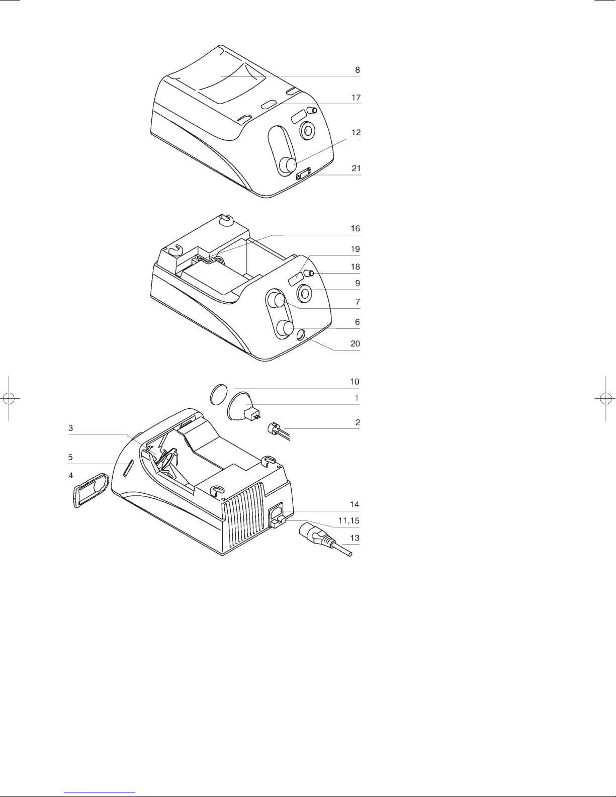
Before initial operation, insert the halogen lamp. The device cover must be
removed for this purpose.
▼Press the release button (17)
▼Remove the cover (8)
During the following operating steps, do not touch the quartz envelope
of the inside of the reflector! This could lead to a premature failure of
the lamp.
▼Remove all transport packaging (e.g. carton for lamp socket)
▼Fit lamp socket (2) on contact pins of the lamp without tilting.
▼Insert lamp (1) into lamp holder (3) without tilting and push to the stop. If the
lamp features an alignment feather, observe the correct engagement.
▼Attach the cover (8) (self-engaging)
▼Insert the fiber-optic light guide in the connection (9) to the stop. For fiber-
optic light guides with feather pin, it must be inserted in the key to the stop.
Ensure that the rotary knob (7 or 12) is in position “Off“ (0-position).
▼Insert the power plug
▼Activate the device by turning the rotary knob (7 or 12) clockwise.
The device may only be operated using the power supply voltage indi-
cated. The specified power supply voltage can be found on the identifi-
cation label at the bottom of the device. Only connect the unit to grounded
sockets.
Keep air vents free!
Do not operate the device with open cover (8)!
The device has not been approved for operation in potentially explosive atmos-
pheres!
Switch the device on or off
Operate the rotary knob (7 or 12 depending on the model).
▼Position 0: Device is switched off.
▼Position 1: Device is switched on.
Adjust brightness (electrically)
▼Turn the brightness knob (7 or 12)
Turning the brightness knob clockwise continuously increases the lamp voltage
and the brightness. Turning it counterclockwise reduces the brightness.
Only adjust as much brightness as required because the useful life of the bulb
decreases with increasing brightness.
Average1life of the bulb:
Control position PL 1000 PL 2000 PL 3000 / PL 3000R
(B) (B) (B), (D), (F), (Ra), (Rs)
4 770 h 3000 h 1500 h
6 70 h 360 h 160 h
1Note: Average life means that 50% of the bulbs may already have failed!
An increase of the lamp voltage by 6% already means a useful life reduction of 50%. On
the other hand, a 6% reduction means doubling the useful life!
Adjusting brightness with mechanical aperture (“B“ versions)
If you want to change the brightness without changing the color temperature,
you should operate the mechanical hole matrix aperture. Turning the knob (6)
clockwise increases the brightness up to the maximum. Turning it counterclock-
wise reduces the brightness up to approx. 1% of the maximum setting. These
settings do not affect the life of the bulb.
Of course, it is possible to operate the electrical brightness control, although
the color temperature changes again. If both brightness controls are used, it
results in a control range of 100% to approx. 0.1%.
Replacing the slide-in filter
▼Remove the slide-in filter mount (4) from the slide-in filter guide (5).
▼Slide the desired filter with mount into the slide-in filter guide until it enga-
ges.
Color and fluorescence filters can be used here for specific applications.
Use only original filters; otherwise, a thermal destruction of the
filter and the device cannot be ruled. Note that the filter and
the entire holder may become very hot during operation. Let the device cool
down sufficiently before removing the filter!
Operating the flip-in filter (“F“ versions)
A daylight filter (18) can be flipped in and out. Observe the imprint on the hou-
sing and the index on the rotary knob.
▼Turning clockwise: Filter is flipped out
▼Turning counterclockwise: Filter is flipped in
This filter increases the color temperature of the halogen light from 3200 K
(Kelvin) to 5600 K, while naturally lowering the brightness.
Display (“D“ versions)
The display (19) shows the current color temperature that changes using the
electronic control.
In addition, a fan failure (display: FAn) and a bulb failure (display: buLb) are
detected and displayed.
If the light source is in STANDBY mode (e.g. with remote control via analog
DIN socket “Rs“), “Stby“ is displayed.
For the display to show the correct color temperature, it must be informed
which bulb is used.
EJA bulbs have a slightly higher color temperature than EKE bulbs. The EKE
bulb is set by default.
INSTALLATION AND CONNECTION
ok_PL_BA_e_07 14.03.2007 22:55 Uhr Seite 8

After switch-on, the SETUP mode is reached by activating the potentiometer. As
long as a small dot is shown at the top left, the SETUP mode can be activated
by turning the potentiometer up and down twice, whereby a slow movement of
the potentiometer increases the display time of the dot. If the dot disappeared,
the SETUP mode can no longer be activated.
To recognize an up and down movement of the potentiometer, the poten-
tiometer must be moved from a position less than 2 to a position greater
than 3 and finally back to less than 2 in approx. 1 second. The device must not
be switched off during this time!
SET displayed in SETUP mode. If the potentiometer is now turned up and down
once in a short time, the SETL mode is activated (bulb setting mode). Wait until
the display switches to the currently set bulb (e.g. L 1), and then scroll through
the possible values (here: 1 for EKE, 2 for EJA) by turning the potentiometer up
and down. After a short pause, the set value flashes and must immediately be
confirmed by turning the potentiometer up and down (after confirmation, the
values stops flashing); otherwise, the value is not stored.
The SETUP mode is now finished, but as long as the dot is still visible at the
tope left the SETUP mode can be reactivated by turning the potentiometer twice
up and down.
If the device features an RS232 socket, the display is used for additional set-
tings (e.g. address, baud rate). An exact description of the setting options in
connection with the RS232 interface can be found on the supplement sheet
accompanying the light source.
Analog remote socket (“Ra“ versions)
The 6-pin DIN socket (20) can be used to remotely control the light source. Pos-
sible actions are:
▼Switch to STANDBY mode
▼Control electrically
An exact technical description of the socket and the accessories can be found
on the supplement sheet accompanying the light source.
RS232 socket (“Rs“ versions)
The D-Sub socket (21) can be used to remotely control the light source via an
RS232 interface. Possible actions are:
▼Switch to STANDBY mode
▼Control electrically
▼Remotely control several light sources
▼Querying error reports
An exact technical description of the interface and the accessories can be found
on the supplement sheet accompanying the light source.
English
ok_PL_BA_e_07 14.03.2007 22:55 Uhr Seite 9

TROUBLESHOOTING
▼First, check whether the power cable is inserted at the light source and in a working power socket.
▼Ensure the that light source is switched on.
No light
Cause Fault elimination
Defective bulb: Replace bulb
Defective fuse: Replace primary fuse
Temperature monitor tripped: The device overheated. Clear ventilation holes and let the device cool down until it switches itself on again.
(does not apply to PL 1000)
Defective lamp socket Replace lamp socket
Defective switched-mode power supply Return device for repair
Insufficient light (not for PL 1000)
Cause Fault removal
Bulb remains at the minimum setting (dimmed) despite moving the electrical brightness knob.
Fan failure: Return device for repair
Note: A defective bulb can also cause a fan standstill or a speed reduction.
REPLACING DEFECTIVE PARTS
Use only original spare parts! If this is not done, it can lead to personal
injury and material damage. Refer to the “Spare Parts“ section for com-
ponent codes. Repairs which are not described in this document must only be
carried out by authorized workshops!
Before opening the device, always pull the power plug!
Do not touch the quartz envelope or the inside of the lamp reflector! This
drastically shortens the life of the bulb. Grasp the bulb only at the outsi-
de of the reflector or close to the contact pins. Always let hot bulbs and their
environment cool off sufficiently.
Replacing the bulb
Light source and bulb must be cooled off sufficiently before changing the
bulb!
▼Switch off the device (7, 12) and pull the power plug (13)
▼Let the defective bulb cool off (min. 10 minutes).
▼Press the release button (17)
▼Remove the cover (8)
During the following operating steps, do not touch the quartz envelope
and the inside of the reflector!
▼Pull up the defective halogen lamp (1) together with the lamp socket (2) from
the lamp holder (3)
▼Pull the defective bulb (1) out of the lamp socket (2)
▼Insert the new bulb in the lamp socket (2) without tilting
▼Insert lamp (1) into lamp holder (3) without tilting and push to the stop. If the
lamp features an alignment feather, observe the correct engagement.
▼Attach the cover (8) (self-engaging)
Replacing the lamp socket
As soon as the lamp socket (2) shows burn-off signs between the contacts, it
must be replaced.
As a guiding value, a replacement of the lamp socket is recommended after 5
replaced bulbs.
▼The procedure is identical to that described in the chapter “Replacing the
bulb“ up to the item “Remove the defective bulb (1) from the lamp socket
(2)“.
▼Release 2 screws in the clamping bead (16) and pull out the old lamp socket.
▼Pull the new lamp socket through the loop, insert it in the clamping bead
and tighten the screws.
▼The additional procedure is identical to that described in the chapter
“Replacing the bulb“ starting with the item “Insert new bulb in the lamp
socket (2) without tilting“.
Replacing the heat-absorbing filter (PL 2000, PL 3000 and PL 3000R)
Gasp the heat-absorbing filter only at the outer diameter! Do not
contaminate the surfaces. Light source and heat-absorbing filter
must be cooled off sufficiently before replacement. The heat-absorbing filter
continues to be very hot after being switched off!
▼Switch off the device (7, 12) and pull the power plug (13)
▼Press the release button (17) and remove the cover (8)
▼Completely remove the broken heat-absorbing filter (10)
▼Insert the new heat-absorbing filter in the spring guide
▼Attach the cover (8) (self-engaging)
Replacing the primary fuse
Use only original fuses according to the chapter “Technical
Data“
▼Switch off the device (7, 12) and pull the power plug (13)
▼Pull out the fuse tray (15) (snap lock).
▼Remove defective fuses (11) and replace them with spare fuses (12).
▼Snap in the fuse tray 15) again.
ok_PL_BA_e_07 14.03.2007 22:55 Uhr Seite 10

The design of the product is under constant review, and although every effort is made to keep this manual up to date, we reserve the right to change specifications at
any time without prior notice. Not responsible for typografical and misprint errors.
English
PL 1000 PL 2000 PL 3000/PL 3000R
Halogen lamp (1) EOGH-EKZ EOGH-64637 EOGH-EKE / EOGH-EJA
Lamp socket (2) EOG-FH.006 EOG-FH.006 EOG-FH.006
Heat-absorbing filter (10) – 593-56-026 593-56-026
Slide-in filter mount, empty (4) 593-37-006 593-37-006 593-37-006
Primary fuse for 230-240 V (11) ESG5-T0.5 ESG5-T1.25 ESG5-T1.25 not PL3000R(B)
Primary fuse for 100-120 V (11) ESG5-T0.8 ESG5-T2.5 ESG5-T2.5
Primary fuse for 100-240 V (11) – – ESG5-T2.5 for PL3000R(B)
PL 1000, PL 2000, PL 3000/PL 3000R
6-pin Din plug for “Ra” EVR04-S6S (DIN 41524)
Slide filter, blue 593-30-001
Slide filter, green 593-30-002
Slide filter, yellow 593-30-003
Slide filter, red 593-30-004
Slide filter daylight 5600K 593-30-005
Power supply cable 3-pin IEC320 for:
EU ELN-3.001
CH ELN-3.002
JELN-3.003
UK ELN-3.004
AUS ELN-3.006
IT ELN-3.009
USA “Hospital Grade“ ELN-3.010
Flexible fiber-optic light guide
Available in different diameters and lengths, single and double-armed
Active diameter 3 / 4.5 / 7 mm
Length 800 / 1200 / 1600 mm
Incident lights
The fiber optic incident light illumination consists of a double-armed gooseneck, which is mounted directly to the microscope stand and connected with the cold-light
source via a flexible fiber-optic light guide.
Active diameter per arm 4 mm
Connecting cable 800 / 1600 mm
Long goosenecks 2-armed 550 mm
Goose-neck light guide
1 and 2-armed available
Active diameter per arm 4 mm
Arm length 550 mm
Ring illuminators
Available as 4-segment ring illuminator and as split ring illuminator with flexible connecting cables of different lengths. A variety of adapters allows for optimum use
and the application for all types of stereomicroscopes.
Inner diameter 66 mm
Height 24 mm
Length of connecting cable 800 / 1200 / 1600 mm
Accessories for ring illuminators
The polarization filter set is used to suppress reflections. The diffuser allows for an optimum, homogenous and shadow-free illuminated area. The fluorescence filter
set is used for examining fluorescence in the visible area. Adapters are available for all stereomicroscopes. A focusing mount allows for light concentration according
to the desired working distance.
Backlight
The backlight is used for transmitted illumination of transparent objects. Up to 2 flexible fiber-optic light guides can be used for illumination.
Insert filters
Color insert filters are available in many versions. The filter mounts allow for a simple filter exchange.
Filter diameter 30 mm
Filter types blue, green, yellow, red and daylight
Filter and focusing attachments
Can be used together with all flexible fiber-optic light guides, goosenecks and fiber optic incident lights. A high-quality focusing attachment, an extensive filter range
and a diffuser can be combined and are available for a variety of applications.
SPARE PARTS AND ACCESSOIRES
ok_PL_BA_e_07 14.03.2007 22:55 Uhr Seite 11

1 Halogenlampe
2 Lampensockel
3 Lampenhalter
4 Filterhalter
5 Führung für Filterhalter
6 Mechanische Helligkeitsregelung („B“-Modelle)
7 Siehe 12, nur bei „B“-Modellen
8 Deckel mit Tragegriff
9 Anschluß für Lichtleiter
10 Wärmeschutzfilter
11 Primärsicherung
12 Ein/Aus Drehschalter
+ elektrischer Helligkeitsregler
13 Netzkabel
14 Buchse für Netzkabel
15 Sicherungshalter
16 Klemmleiste für Lampensockel
17 Entriegelungsknopf
18 Einschwenkfilter („F“-Modelle)
19 Display („D“-Modelle)
20 Analoge Remote Buchse („Ra“-Modelle)
21 RS232 Buchse („Rs“-Modelle)
ok_PL_BA_d_07 13.03.2007 11:29 Uhr Seite 2

Bitte lesen Sie vor Inbetriebnahme der Kaltlichtquelle die komplette Bedienungsanleitung!
Technische Daten
Typenbezeichnung PL 1000 PL 2000 PL 3000 PL 3000R
Mögliche VariantenB B B, D, F, Ra, Rs B
Artikelnummer 230-240 V ±10% 596-20-1501596-20-250 596-20-350
100-120 V ±10% 596-20-160 596-20-260 596-20-360
100-240 V ±10% 596-20-380
Netzfrequenz 50–60 Hz 50–60 Hz 50–60 Hz 50–60 Hz ±5%
Leistungsaufnahme max 50 VA max 150 VA max 200 VA max 200 VA
Lampenspannung max. 11,9 V max 13 V max 21,4 V max 21,4 V
Halogen-Reflektorlampe 30 W/10,8 V 100 W/12 V 150 W/21 V 150 W/21 V
Primärsicherung 230/240 V T500 mAH T1,25 AH T1,25 AH T2,5 AH für
100/120 V T800 mAH T2,5 AH T2,5 AH 100–240 V
IEC 127-2/5 & UL, 5 x 20 mm, time-lag (träge)
Dimensionen Höhe/Breite/Tiefe 120/168/268 mm 120/168/268 mm 120/168/268 mm 120/168/268 mm
Gewicht 1,3 kg 1,5 kg 1,6 kg 1,6 kg
Farbtemperatur 3200 K 3250 K 3250 K 3250 K
Durchmesser Lichtleiter max. 10 mm 13 mm 13 mm 13 mm
Betriebsumgebung 10–40 °C2und 30–70 % relative Luftfeuchte
Lagerung/Transport 0–40 °C und 30–70 % relative Luftfeuchte
Schutzart (Schutzklasse) I I I I
Deklaration CE CE CE CE
Medizinische Klassifizierung
(nur bei MED-Varianten) – BF BF –
1bei PL1000 nur 230 V (nicht 230-240 V)
2Die Lichtquellen sind zwar für den Betrieb bis 40 °C geeignet, doch sinkt die Lebensdauer von Elektronikbauteilen und Lampe extrem. Für optimalen Betrieb sollte die Umgebungstemperatur nicht höher sein als 25 °C.
BESCHREIBUNG
Mit dem Kauf dieses Produktes erwerben Sie eine hochwertige Kaltlichtquelle,
die überall dort Anwendung findet, wo man viel Licht ohne Wärmeentwicklung
benötigt. Sie dient zur Objektbeleuchtung bei Mikroskopen. Zumeist werden
faseroptische Ringlichter angesteckt, die am Mikroskopobjektiv befestigt wer-
den. Alternativ kann man Schwanenhälse oder flexible Lichtleiter anstecken.
Als Leuchtmittel dienen dabei Halogenkaltlichtspiegellampen (1) unterschied-
licher Leistungsabstufungen. Mittels eines speziellen Wärmeschutzfilters (10)
wird die Wärme reflektiert, wobei das benötigte sichtbare Licht zur Gänze
durchgelassen wird. Um die entstehende Wärme abführen zu können, ist bei
allen Typen außer der PL1000 ein Axiallüfter eingebaut. Das Leuchtmittel wird
durch einen elektronischen Schaltnetzteil betrieben, der dem neuesten Stand
der Technik entspricht und speziell für diese Kaltlichtquellen entwickelt wurde.
Um das Gerät einzuschalten, drehen Sie den Knopf (7 oder 12) im Uhrzeigersinn,
von einer Minimumstellung bis zur Maximalstellung. Drehen Sie ihn ganz nach
links, bis ein deutliches Klicken hörbar wird, um die Kaltlichtquelle abzuschal-
ten. Mit diesem Stellknopf wird die Kaltlichtquelle elektrisch geregelt
(gedimmt). Dadurch ändert sich aber auch die Farbtemperatur, sodass im
gedimmten Zustand das Licht rötlicher erscheint als in der Maximalstellung.
Wird eine konstante Farbtemperatur gefordert, so muss mit einer Lochraster-
blende das Licht mechanisch abgeblendet werden.
Alle Ausführungen mit dem Buchstaben „B“ in der Typenbezeichnung besitzen
zusätzlich zur elektronischen Helligkeitsregelung ein Blendenrad, mit dem man
die Lichtmenge von 100% bis ca. 1% bei gleichbleibender Farbtemperatur
regeln kann. Zusätzlich kann natürlich auch elektronisch geregelt werden, wobei
sich dann die Farbtemperatur wiederum ändert. Mit dem Einschubfilter (4) kön-
nen diverse Filter in das Gerät geschoben werden.
Deutsch
BEDIENUNGSANLEITUNG FÜR
PL 1000 (B), PL 2000 (B), PL 3000 (B) (D) (F) (Ra) (Rs) und PL 3000R (B)
Alle Ausführungen mit Display (19) (erkennbar am Buchstaben „D“ in der Typen-
bezeichnung) zeigen beim elektrischen Dimmen die aktuelle Farbtemperatur an.
Zusätzlich werden Lüfter- und Lampenausfall am Display angezeigt.
Alle Ausführungen mit einem „F“ in der Typenbezeichnung besitzen an der Front
eine Einschwenkvorrichtung (18) für einen Filter (Tageslichtfilter für eine Farb-
temperatur von ca. 5600K).
„Ra“ in der Typenbezeichnung bedeutet, dass die Lichtquelle eine DIN-Buchse
für die Fernsteuerung (20) besitzt. Damit kann man die Lichtquelle analog dim-
men und in den Standby-Modus schalten.
„Rs“ in der Typenbezeichnung bedeutet, dass die Lichtquelle eine 9-polige
RS232 D-Sub Buchse (21) besitzt. Hiermit kann die Lichtquelle über eine RS232
Schnittstelle gedimmt und in den Standby-Modus geschalten werden. Bei
gleichzeitigem Vorhandensein eines Displays kann man die Adressbelegung und
andere RS232 Daten abfragen.
Die Ausführungen „Rs“ und „Ra“ können nicht zugleich in einem Gerät gebaut
werden.
PL3000R(B) besitzt eine analoge Remotebuchse, die den Anschluss einer Hand-
fernbedienung bzw. eines seriellen Interfaces zur computerunterstützten Steue-
rung der Lichtquelle ermöglicht (Zubehör: RS232-Interface und Fernsteuerung,
für Pinbelegung siehe Zubehörbeschreibung). Weiters kommt hier ein PFC
(power factor correction) Schaltnetzteil zur Anwendung, der einen weltweiten
Betrieb der Lichtquelle ermöglicht (100-240 V) und zugleich rippelfrei ist.
ok_PL_BA_d_07 13.03.2007 11:29 Uhr Seite 3

Sicherungssymbol: Verwenden Sie nur Sicherungen des angeführten
Typs!
Intensitätsskala: Je größer der Wert ist, den Sie einstellen, desto mehr
Licht erhalten Sie!
CE Konformitätszeichen: Bestätigt Konformität mit Niederspannungs-
richtlinie (Leuchten) 73/23/EEC und EMV-Richtlinie 89/336/EEC.
cTÜVus Zeichen: bestätigt Konformität mit UL2601-1.
Leuchten, geeignet zur direkten Befestigung auf normal entflammbaren
Befestigungsflächen.
Das Baujahr ist an diesem Symbol ersichtlich und lässt
sich aus der 1. (linken) Stelle der 5stelligen Geräte-Serien-
nummer am Typenschild ableiten. (z.B. 01234 bedeutet Baujahr 2000,
41234 Baujahr 2004).
Einige Lichtquellen gibt es auch in Medizin-Ausführung (erkennbar am
hier nebenan abgebildeten „BF“ Symbol am Typenschild) für Anwendun-
gen im medizinischen Bereich. Diese Lichtquellen erfüllen zusätzlich zur
Leuchtennorm EN60598 auch noch die Norm für Medizinische Elektri-
sche Geräte EN60601-1, allerdings ist vom Systemhersteller die CE
Deklaration für Medizinprodukte unbedingt einzuholen. Die Lichtquelle
wird nur als Komponente eines Systems betrachtet und besitzt selbst
keine CE Deklaration für Medizinprodukte. Ohne dieser CE Deklaration
darf die Lichtquelle nicht im medizinischen Bereich eingesetzt werden.
Weiters müssen alle nationalen Gesetze eingehalten werden. Diese
MED-Lichtquellen sind gebaut für Anwendungsteile vom Typ BF, das
heißt, der Lichtleiteranschluss (Flansch) ist vom restlichen Gerät und
von der Schutzerde isoliert.
Die Lichtquelle darf nicht mit dem Patienten in Kontakt kommen!!
Betrieb der Lichtquellen in den USA und Kanada:
Ist das „cTÜVus“ Symbol am Typenschild angebracht, so ist das
Gerät konform zu UL2601-1 gebaut. Alle anderen für den Betrieb notwendigen
Normen und Gesetze für Medizinprodukte (FDA, FCC...) muss der lokale Händler
erfüllen und dem Betreiber nachweisen. Ohne dieser Nachweise darf das Gerät
nicht im Medizin-Bereich in Betrieb genommen werden.
Außerdem ist darauf zu achten, dass diese Lichtquellen mit einem speziellen
„Hospital-Grade“ oder „Hospital Only“ Netzkabel auszustatten sind. Die Licht-
quelle darf nicht mit dem Patienten in Kontakt kommen!!
In dieser Betriebsanleitung werden folgende Gefahrensymbole verwendet:
Warnung vor gefährlicher elektrischer Spannung!
Warnung vor einer Gefahrenstelle.
Begleitende Dokumentation beachten!
Warnung vor heißen Oberflächen!
Dieses Kapitel behandelt die Sicherheitshinweise, die beim Einsatz des Gerätes
unbedingt einzuhalten sind. Eine andere Verwendung als in dieser Bedienungs-
anleitung beschrieben ist nicht zulässig und kann zu Beschädigungen dieses
Produktes führen oder Gefahren hervorrufen!
Beachten Sie in Ihrem eigenen Interesse alle Sicherheitshinweise, die auf dem
Gerät und in dieser Bedienungsanleitung angeführt werden.
Zielpublikum: Personen, die mit dem Gerät oder Zubehör dieses Gerätes arbei-
ten, müssen diese Bedienungsanleitung unbedingt lesen und der Betreiber muß
sicherstellen, das die Benutzer den Inhalt dieser Anleitung verstanden haben. Dies
gilt insbesondere für das Kapitel „Hinweise zu Ihrer Sicherheit“.
Produktbeobachtungspflicht: Der Benutzer muss bei Veränderungen des
Betriebsverhalten oder an sicherheitsrelevanten Geräteteilen den Betrieb sofort
einstellen (Netzstecker ziehen!) und eine zuständige Person oder den Hersteller
darüber informieren.
Aufbewahrungsort der Betriebsanleitung: Es wird empfohlen, die Betriebs-
anleitung in unmittelbarer Nähe des Geräts aufzubewahren, um sicherzustellen,
dass sie im Bedarfsfall sofort vom Benutzer eingesehen werden kann.
Gesetzliche Vorschriften: Die allgemein gültigen nationalen und lokalen
Sicherheits- und Unfallverhütungsvorschriften und Gesetze sind ebenso einzu-
halten wie die ergänzenden Benutzerrichtlinien des Betreibers.
Technische Änderungen am Gerät sind in jedem Fall zu unter-
lassen!
Achtung! Die Lampe und Teile in unmittelbarer Nähe können
heiß sein. Die heiße Lampe und benachbarte Teile können bei
Berührung zu Verbrennungen führen. Vor dem Abnehmen des Deckels und
Wechseln der Lampe muss man das Gerät unbedingt ausreichend abkühlen las-
sen (ca. 10-15 Minuten). Unbedingt den Netzstecker vorher abziehen!
Die Halogen-Reflektorlampe muss für optimale Funktion exakt platziert sein.
Blicken Sie niemals direkt in die Lampe oder Lichtleiter, wenn diese ein-
geschaltet ist, da Sie sonst Augenverletzungen riskieren!
Als verbindliche Einsatzgrenzen gelten die Angaben im Kapitel „Technische
Daten“.
Betreiben Sie das Gerät nicht in der Nähe von Wasser oder in Räumen mit
extremer Luftfeuchtigkeit.
In unmittelbarer Nähe des Gerätes sollen niemals brennbare Materialien plat-
ziert sein. Das Gerät ist von jeglichen Hitzequellen fernzuhalten. Dieses Produkt
ist nicht für den Einsatz in explosionsgefährdeten Bereichen zugelassen! Nicht
für den Einsatz mit brennbaren Gemischen (wie z.B. Anästhesiemittel, Sauer-
stoff oder Desinfektionsmittel....) geeignet!
Halten Sie die Lüftungsöffnungen des Gerätes stets frei, um keine Überhitzung
zu verursachen. Stellen Sie sicher, dass die freie Luftumwälzung durch nichts
beeinträchtigt wird.
Verschütten Sie niemals Flüssigkeit auf dem Gerät, und schieben Sie keine
Fremdkörper in das Gerät! Sie könnten dadurch Elektroschocks oder Geräteschä-
den auslösen.
Das Gerät darf nur mit der vorgeschriebenen Netzspannung betrieben werden.
Öffnen Sie niemals das Gerät oder Komponenten, außer es wird später in dieser
Anleitung ausdrücklich darauf hingewiesen.
VERWENDETE SYMBOLE AM GERÄT HINWEISE ZUR IHRER SICHERHEIT
ok_PL_BA_d_07 13.03.2007 11:29 Uhr Seite 4

Reinigung: Trennen Sie das Produkt vor der Reinigung vom Stromnetz und
verwenden Sie zur Reinigung nur ein feuchtes Tuch aber auf keinen Fall brenn-
oder entflammbare Flüssigkeiten. Falls versehentlich Flüssigkeit ins Innere des
Geräts gelangt, Gerätestecker sofort abziehen und Gerät zur Servicestelle
bringen.
Wartung: Sämtliche nationale Gesetze und Normen für regelmäßige Inspektion
müssen vom Betreiber eingehalten werden. Spätestens alle 2 Jahre muß eine
Inspektion durchgeführt werden, die nur von Fachkräften ausgeführt werden
darf, die die Sicherheit des Gerätes beurteilen, mögliche Auswirkungen und
Gefahren erkennen und die Richtlinien- und Normenkonformität feststellen
können. Diese Prüfungen sollten mindestens umfassen:
Schutzleiter Prüfung, Ableitstrom Prüfung, Sichtkontrolle mit Reinigung und
Funktionstest
Ersatzteile: Es dürfen nur Originalersatzteile verwendet werden. Andernfalls
können Personen- oder Sachschäden entstehen. Die Artikelnummern sind im
Kapitel „Ersatzteile“ angeführt.
Verantwortung: Der Betreiber ist als übergeordnete juristische Person verant-
wortlich für die bestimmungsgerechte Verwendung des Produkts sowie für die
Information anderer Benutzer und legt die Kompetenzen für die Gerätebedie-
nung fest.
Entsorgung: Beachten Sie alle nationale Umweltauflagen und Gesetze für die
Entsorgung des Gerätes oder Teile dessen. Trennen Sie die Komponenten (z.B.
nach Kunststoff, Elektronik, Lampen, Metalle...) und entsorgen Sie diese bei
nationalen Entsorger!
Ziehen Sie das Netzkabel ab, wenn das Gerät längere Zeit unbenutzt bleibt.
Verwenden Sie nur Original-Netzkabel und verlegen Sie das Kabel so, dass es
weder eingeklemmt noch durchtrennt werden kann. Verwenden Sie aus Sicher-
heitsgründen ausschließlich ein 3-poliges Netzkabel mit Schutzleiter.
In dieser Broschüre nicht beschriebene Reparaturen dürfen nur von autorisierten
Werkstätten durchgeführt werden.
Der Hersteller haftet nicht für Schäden durch Nichtbeachtung obiger Hinweise!
Stand der Technik: Dieses Produkt entspricht dem letzten Stand der Technik
unter Verwendung anerkannter sicherheitsrelevanter Normen und Regeln.
Dieses Gerät wurde nach folgenden Richtlinien und Standards konstruiert und
gebaut.
▼73/23/EEC: Niederspannungsrichtlinie (CE)
▼89/336/EEC: Elektromagnetische Verträglichkeit (CE)
▼EN 60598-1: Leuchten
▼EN 60601-1: Medizinische elektrische Geräte (bei MED Varianten)
▼UL 2601-1: Medical Electrical Equipment (bei MED Varianten)
Deutsch
ok_PL_BA_d_07 13.03.2007 11:29 Uhr Seite 5

Dieses Kapitel beschreibt die in der EN60601-1-2 (Elektromagnetic compatibili-
ty) geforderten Maßnahmen zur Gewährleistung der Elektomagnetischen Ver-
träglichkeit (EMV).
Medizinische Elektrische Geräte unterliegen besonderen Vorsichtsmaß-
nahmen hinsichtlich der EMV. Eine Nichtbeachtung dieser Hinweise
kann zu einer erhöhten Aussendung oder zu einer reduzierten Störfestigkeit des
Gerätes oder Systems führen! Tragbare und mobile HF-Kommunikationseinrich-
tungen können medizinische elektrische Geräte beeinflussen!
Verwenden Sie im medizinischen Bereich und Anwendungsfall aus-
schließlich vom Hersteller dafür deklariertes Zubehör!
Stellen Sie das Gerät nicht unmittelbar neben andere und vermeiden Sie die
Stapelung mit anderen Geräten. Sollte dies dennoch der Betrieb unbedingt
erfordern, so ist das Gerät und System genau zu beobachten, damit der bestim-
mungsgemäße Betrieb in dieser Anordnung überprüft werden kann!
Verwenden Sie nur mitgelieferte Netzkabel (max. 2,5 m)! Längere und andere
Netzkabel können zu einer erhöhten Aussendung oder zu einer reduzierten Stör-
festigkeit des Gerätes oder Systems führen!
EMV WARNHINWEISE
Elektromagnetische Störaussendung
Das Gerät ist für den Einsatz in der unten beschriebenen elektromagnetischen Umgebung vorgesehen.
Der Kunde oder Benutzer des Gerätes muss sicherstellen, dass der Einsatz in einer entsprechenden Umgebung erfolgt.
Störaussendungsprüfung
HF-Störaussendungen
CISPR 11
HF-Störaussendungen
CISPR 11
Harmonische Störaussendungen
IEC 61000-3-2
Spannungsschwankungen/Flicker-Störaussendungen
IEC 61000-3-3
HF-Störaussendungen
CISPR 15
Konformität
Gruppe 1
Klasse B
Klasse C
Konform
Konform
Elektromagnetische Umgebung – Anleitung
Das Gerät verwendet HF-Energie nur für die interne Funktion. Daher sind die HF-Störaussendungen sehr gering,
so dass sie in der Regel keine Störungen bei in der Nähe aufgestellten elektronischen Geräten verursachen.
Das Gerät ist zum Einsatz in allen Einrichtungen geeignet, einschließlich Wohnbereichen und solcher Einrich-
tungen, die direkt an das öffentliche Niederspannungs-Versorgungsnetz, mit dem Wohngebäude versorgt wer-
den, angeschlossen sind.
Elektromagnetische Störfestigkeit
Das Gerät ist für den Einsatz in der unten beschriebenen elektromagnetischen Umgebung vorgesehen.
Der Kunde oder Benutzer des Gerätes muss sicherstellen, dass der Einsatz in einer entsprechenden Umgebung erfolgt.
Störfestigkeitsprüfung
Elektrostatische Entladung
IEC 61000-4-2
Schnelle transiente elektrische Störgrößen/Burst
IEC 61000-4-4
Stoßspannung
IEC 61000-4-5
Spannungseinbrüche, Kurzzeitunterbrechungen
und Spannungsschwankungen
an Netzeingangsleitungen
IEC 61000-4-11
Netzfrequenz (50 Hz/60 Hz)
Magnetfeld
IEC 61000-4-8
IEC 60601-Messpegel und Konformitätsstufe
± 6 kV Kontakt
± 8 kV Luft
± 2 kV für Stromversorgungsleitungen
± 1 kV für Eingangs-/Ausgangsleitungen
± 1 kV Gegentakt
± 2 kV Gleichtakt
< 5 % UT(> 95 % Reduktion in UT) für 1/2 Periode
40 % UT(60 % Reduktion in UT) für 5 Perioden
70 % UT(30 % Reduktion in UT) für 25 Perioden
< 5 % UT(> 95 % Reduktion in UT) für 5 s
3 A/m
Elektromagnetische Umgebung – Anleitung
Böden sollten aus Holz, Beton oder Keramikfliesen sein. Falls Böden mit syntheti-
schem Material bedeckt sind, sollte die relative Luftfeuchtigkeit mindestens 30 %
betragen.
Die Netzanschlussqualität sollte der einer typischen Geschäfts- oder Krankenhaus-
umgebung entsprechen.
Die Netzanschlussqualität sollte der einer typischen Geschäfts- oder Krankenhaus-
umgebung entsprechen.
Die Netzanschlussqualität sollte der einer typischen Geschäfts- oder Krankenhaus-
umgebung entsprechen. Wenn der Einsatz des Gerätes kontinuierlichen Betrieb bei
Unterbrechungen der Stromversorgung erfordert, wird empfohlen, das Gerät an
eine unterbrechungsfreie Stromversorgung oder eine Batterie anzuschließen.
Magnetfelder mit energietechnischen Frequenzen sollten Pegel aufweisen, die für
einen typischen Standort in einer typischen Geschäfts- oder Krankenhausumge-
bung charakteristisch sind.
ANMERKUNG: UTist die Wechselspannung vor Anwendung des Messpegels.
ok_PL_BA_d_07 13.03.2007 11:29 Uhr Seite 6

Deutsch
Elektromagnetische Störfestigkeit
Das Gerät ist für den Einsatz in der unten beschriebenen elektromagnetischen Umgebung vorgesehen.
Der Kunde oder Benutzer des Gerätes muss sicherstellen, dass der Einsatz in einer entsprechenden Umgebung erfolgt.
Störfestigkeitsprüfung
Leitungsgebundene HF
IEC 61000-4-6
Abgestrahlte HF
IEC 61000-4-3
IEC 60601-Messpegel
3 Veff
150 kHz bis 80 MHz
3 V/m
80 MHz bis 2.5 GHz
Konformitätsstufe
3 ➔
V
1 in V
3 ➔
E
1 in V/m
Elektromagnetische Umgebung – Anleitung
80 MHz bis 800 MHz 800 MHz bis 2,5 GHz
Tragbare und mobile HF-Kommunikationsgeräte sollten zu allen Teilen des Gerätes, einschließlich der Kabel, immer mindestens den empfohlenen Abstand einhalten, der aus der auf die Fre-
quenz des Senders anwendbaren Gleichung berechnet wird: Empfohlener Abstand:
Dabei ist P die maximale Ausgangsnennleistung des Senders in Watt (W) laut Senderhersteller und d der empfohlene Abstand in Metern (b). Feldstärken von ortsfesten HF-Sen-
dern, ermittelt durch eine elektromagnetische Standortübersicht (a), sollten unterhalb der Konformitätsstufe in jedem Frequenzbereich (b) liegen.
Störungen können in der Nähe von Geräten, die mit folgendem Symbol markiert sind, auftreten:
Bei 80 MHz und 800 MHz gilt der höhere Frequenzbereich. Diese Richtlinien gelten möglicherweise nicht in allen Situationen. Die elektromagnetische Ausbreitung wird durch die Absorption
und Reflexion von Bauwerken, Objekten und Personen beeinflusst.
(a) Feldstärken von ortsfesten Sendern, z. B. Basisstationen für Funktelefone (Handy/kabellos) und öffentlichen beweglichen Landfunk, Amateurfunk, AM- und FM-Rundfunksendungen und
Fernsehsendungen, können theoretisch nicht mit Genauigkeit vorhergesagt werden. Um die elektromagnetische Umgebung infolge von ortsfesten HF-Sendern zu bewerten, sollte eine
elektromagnetische Standortübersicht in Betracht gezogen werden. Wenn die gemessene Feldstärke an dem Standort, an dem das Gerät eingesetzt wird, die oben genannte anwend-
bare HF-Konformitätsstufe überschreitet, sollte das Gerät überwacht werden, um einen normalen Betrieb zu gewährleisten. Falls eine abnormale Leistung beobachtet wird, können zu-
sätzliche Maßnahmen nötig sein, z. B. Neuausrichtung oder Änderung des Standorts des Gerätes.
(b) Bei einem Frequenzbereich von mehr als 150 kHz bis 80 MHz sollten die Feldstärken kleiner als [V1] V/m sein.
Empfohlene Abstände zwischen tragbaren und mobilen HF-Kommunikationsgeräten und dem Gerät
Das Gerät ist für den Einsatz in einer elektromagnetischen Umgebung vorgesehen, in der HF-Störstrahlungen kontrolliert werden. Der Kunde oder Benutzer des Gerätes kann dazu beitragen,
elektromagnetische Störungen zu vermeiden, indem er einen Mindestabstand zwischen tragbaren und mobilen HF-Kommunikationsgeräten (Sendern) und dem Gerät einhält, der den unten
genannten Empfehlungen entspricht. Die Empfehlungen richten sich nach der maximalen Ausgangsleistung des jeweiligen Kommunikationsgerätes.
Maximale Nennausgangsleistung
des Senders in Watt [W]
0,01
0,1
1
10
100
Abstand gemäß der Senderfrequenz in Metern [m
150 kHz bis 80 MHz
0,12
0,37
1,17
3,69
11,67
Für Sender mit einer hier nicht genannten maximalen Nennausgangsleistung kann der empfohlene Abstand d in Metern [m] mithilfe der auf die Frequenz des Senders anwendbaren Gleichung
ermittelt werden, wobei P die maximale Nennausgangsleistung des Senders in Watt [W] laut Angaben des Senderherstellers ist.
Bei 80 MHz und 800 MHz gilt der höhere Frequenzbereich. Diese Richtlinien gelten möglicherweise nicht in allen Situationen. Die elektromagnetische Ausbreitung wird durch die Absorption und
Reflexion von Bauwerken, Objekten und Personen beeinflusst.
80 MHz bis 800 MHz
0,12
0,37
1,17
3,69
11,67
800 MHz bis 2,5 GHz
0,23
0,74
2,33
7,38
23,33
d =
(
—
)*-
\
/
–
P
3,5
V
1
d =
(
—
)*-
\
/
–
P
3,5
E
1
d =
(
—
)*-
\
/
–
P
7
E
1
d =
(
—
)*-
\
/
–
P
3,5
V
1
d =
(
—
)*-
\
/
–
P
3,5
E
1
d =
(
—
)*-
\
/
–
P
7
E
1
ok_PL_BA_d_07 13.03.2007 11:29 Uhr Seite 7

BEDIENUNG UND BETRIEB
Wählen Sie den zukünftigen Standort nach folgenden Kriterien aus:
▼keine hohe Luftfeuchtigkeit (siehe Technische Daten)
▼normale Raumtemperatur (siehe Technische Daten)
▼Lüftungsschlitze freihalten
▼Nicht für den Einsatz mit brennbaren Gemischen (wie z.B. Anästhesiemittel,
Sauerstoff oder Desinfektionsmittel....) geeignet!
Die Lichtquellen dürfen nicht mit Patienten in Berührung kommen!
Beachten Sie bei Einsatz dieser Lichtquellen in MED Ausführung in medizini-
schen Bereichen alle Hinweise im Kapitel „Beschreibung“
Das Gerät aus der Verpackung nehmen und auf eine ausreichend große horizon-
tale Fläche stellen.
Netzstecker noch nicht anschließen.
Vor der Erstinbetriebnahme die Halogenlampe einsetzen. Zu diesem Zweck muss
der Gerätedeckel abgenommen werden.
▼Entriegelungsknopf (17) drücken
▼Deckel (8) abnehmen
Berühren Sie während der folgenden Arbeitsschritte weder den Quarz-
kolben noch die Reflektor-Innenseite! Dies könnte zu einem frühzeitigem
Ausfall der Lampe führen.
▼Sämtliche Transportverpackungen entfernen (z.B. Karton bei Lampensockel)
▼Lampensockel (2) möglichst ohne Verkippen auf die Kontaktstifte der Lampe
aufstecken.
▼Lampe (1) möglichst ohne Verkippen in den Lampenhalter (3) einschieben
und bis zum Anschlag drücken. Achten Sie bei Lampen mit Orientierungsna-
se auf die korrekte Einrastung.
▼Deckel (8) aufsetzen (rastet selbsttätig ein)
▼Lichtleiter bis zum Anschlag in den Anschluss (9) stecken. Bei Lichtleitern
mit Orientierungsstift ist dieser in der Nut bis zum Anschlag
zu positionieren. Vergewissern Sie sich, dass sich der Drehschalter (7 oder
12) in Stellung „Aus“ (0-Stellung) befindet.
▼Netzstecker einstecken
▼Einschalten durch Betätigung des Drehschalters (7 oder 12) im Uhrzeiger-
sinn.
Das Gerät darf nur mit der vorgeschriebenen Netzspannung betrieben
werden. Die vorgeschriebene Netzspannung ist am Typenschild an der
Unterseite des Geräts ersichtlich. Schließen Sie das Gerät nur an Steckdosen
mit Schutzerde an!
Lüftungsschlitze freihalten!
Das Gerät nicht mit geöffnetem Deckel (8) betreiben!
Das Gerät ist für den Betrieb in explosionsgefährdeten Bereichen nicht zugelas-
sen!
Gerät ein- bzw. ausschalten
Drehschalter (7 oder 12 je nach Model) betätigen.
▼Stellung 0: Gerät ist ausgeschaltet.
▼Stellung 1: Gerät ist eingeschaltet.
Helligkeit regeln (elektrisch)
▼Helligkeitsregler (7 oder 12) drehen
Durch Verdrehen des Helligkeitsreglers im Uhrzeigersinn wird die Lampenspan-
nung und somit die Helligkeit stufenlos erhöht. Drehen gegen den Uhrzeigersinn
bewirkt eine Reduktion der Helligkeit.
Stellen Sie nur soviel Helligkeit ein, wie Sie unbedingt benötigen, denn die Lam-
penlebensdauer sinkt dramatisch mit Erhöhung der Helligkeit.
Mittlere1Lebensdauer der Lampe:
Reglerstellung PL 1000 PL 2000 PL 3000 / PL 3000R
(B) (B) (B), (D), (F), (Ra), (Rs)
4 770 h 3000 h 1500 h
6 70 h 360 h 160 h
1Hinweis: mittlere Lebensdauer bedeutet, dass bereits 50% der Lampen ausgefallen sein
dürfen! Bereits eine Erhöhung der Lampenspannung um 6% bedeutet eine Halbierung der
Lebensdauer. Dafür bedeutet eine Reduktion um 6% eine Verdoppelung der Lebensdauer!
Helligkeit regeln mit mechanischer Blende („B“ Ausführungen)
Falls Sie die Helligkeit verändern möchten, ohne dabei die Farbtemperatur ver-
stellen zu wollen, sollten Sie die mechanischen Lochrasterblende bedienen. Ein
Verdrehen des Knopfes (6) im Uhrzeigersinn erhöht die Helligkeit bis zum Maxi-
mum. Ein Verdrehen gegen den Uhrzeigersinn reduziert die Helligkeit bis etwa
1% der maximalen Stellung. Diese Einstellungen haben keine Auswirkungen auf
die Lebensdauer der Lampe.
Natürlich kann man zusätzlich die elektrische Helligkeitsregelung bedienen,
wobei sich hierbei wieder die Farbtemperatur verändert. Nutzt man beide Hel-
ligkeitsregelungen, so ergibt dies einen Regelbereich von 100% auf ca. 0,1%.
Einschubfilter wechseln
▼Einschubfilter-Fassung (4) aus der Einschubfilter-Führung (5) ziehen.
▼Den gewünschten Filter mit Fassung in die Einschubfilter-Führung bis zum
Einrasten einschieben.
Hier können Farb- und Fluoreszenzfilter für bestimmte Anwendungen einge-
setzt werden.
Verwenden Sie nur Original-Filter, da sonst eine thermische Zer-
störung des Filters und des Gerätes nicht auszuschließen ist.
Beachten Sie, dass der Filter samt Halterung im Gebrauch sehr heiß werden
kann. Lassen Sie das Gerät ausreichend auskühlen, bevor Sie den Filter heraus-
nehmen!
Einschwenkfilter bedienen („F“ Ausführungen)
Hier kann ein Tageslichtfilter (18) ein- und ausgeschwenkt werden. Beachten Sie
dabei den Aufdruck am Gehäuse und des Index am Drehknopf.
▼Drehen im Uhrzeigersinn: Filter ausgeschwenkt
▼Drehen gegen Uhrzeigersinn: Filter eingeschwenkt
Dieser Filter erhöht die Farbtemperatur des Halogenlichtes von 3200K (Kelvin)
auf 5600K, wobei dabei naturgemäß die Helligkeit sinkt.
Display Anzeige („D“ Ausführungen)
Das Display (19) zeigt die aktuelle Farbtemperatur an, die sich mit der elektri-
schen Regelung ändert. Zusätzlich wird ein Lüfterausfall (Anzeige: FAn) und ein
Lampenausfall (Anzeige: buLb) detektiert und angezeigt. Befindet sich die Licht-
quelle im STANDBY Modus (z.B. durch Fernsteuerung mittels analoger DIN
Buchse „Rs“), wird „Stby“ angezeigt.
AUFSTELLEN UND ANSCHLIESSEN
ok_PL_BA_d_07 13.03.2007 11:29 Uhr Seite 8

Damit das Display die korrekte Farbtemperatur anzeigen kann, muss man dem
Display mitteilen, welche Lampe verwendet wird. EJA Lampen haben eine
etwas höhere Farbtemperatur als EKE Lampen. Standardmäßig ist die EKE Lam-
pe eingestellt.
Nach dem Einschalten kommt man durch Potibetätigung in den SETUP-Modus.
Solange ein kleiner Punkt links oben angezeigt wird, kann man durch zweimali-
ges Auf- und Abdrehen des Potis den SETUP Modus aktivieren, wobei ein lang-
sames Bewegen des Potis die Anzeigedauer des Punktes verlängert. Ist der
Punkt verschwunden, kann der SETUP Modus nicht mehr aktiviert werden.
Damit ein Auf- und Abdrehen des Potis erkannt wird, muss das Poti von
Stellung kleiner 2 auf Stellung größer 3 und schließlich wieder auf Stel-
lung kleiner 2 innerhalb von ca. 1 Sekunde gedreht werden. Das Gerät darf
dabei nicht abgeschaltet werden!
Im SETUP Modus wird SET angezeigt. Wenn man nun das Poti innerhalb einer
kurzen Zeit 1x auf- und abdreht, gelangt man in den SETL Modus (Lampenein-
stellmodus). Hier wartet man bis sich die Anzeige auf die aktuell eingestellte
Lampe umschaltet (z.B. L 1), und kann dann mit jeder Poti Auf- und Abdrehung
durch die möglichen Werte (hier: 1 für EKE, 2 für EJA) durchscrollen. Nach einer
kurzen Pause blinkt der eingestellte Wert, den man dann gleich durch eine Poti
Auf- und Abdrehung bestätigen muss (nach Bestätigung hört der Wert zu blinken
auf), da sonst der Wert nicht gespeichert wird.
Nun ist der SETUP Modus beendet, doch solange der kleine Punkt links oben
noch sichtbar ist, kann man den SETUP Modus durch zweimaliges Auf- und
Abdrehen des Potis erneut aktivieren.
Besitzt das Gerät eine RS232 Buchse, wird das Display für zusätzliche Einstel-
lung genützt (z.B. Adresse, Baudrate). Eine genaue Beschreibung der Einstell-
möglichkeiten im Zusammenhang mit der RS232 Schnittstelle finden Sie im Bei-
blatt der Lichtquelle.
Analoge Remote Buchse („Ra“ Ausführungen)
Mit der 6poligen DIN Buchse (20) kann man die Lichtquelle analog fernbedienen.
Mögliche Aktionen sind:
▼in den STANDBY Modus schalten
▼elektrisch Regeln
Eine genaue technische Beschreibung der Buchse und des Zubehörs finden Sie
im Beiblatt der Lichtquelle.
RS232 Buchse („Rs“ Ausführungen)
Mit der D-Sub Buchse (21) kann man die Lichtquelle über eine RS232 Schnitt-
stelle fernbedienen. Mögliche Aktionen sind:
▼in den STANDBY Modus schalten
▼elektrisch Regeln
▼mehrere Lichtquellen fernsteuern
▼Fehlermeldungen abfragen
Eine genaue technische Beschreibung des Interfaces mit Zubehör finden Sie im
Beiblatt der Lichtquelle.
Deutsch
ok_PL_BA_d_07 13.03.2007 11:29 Uhr Seite 9

STÖRUNGSBEHEBUNG
▼Prüfen Sie zunächst, ob das Netzkabel an der Lichtquelle und an einer funktionierenden Netzsteckdose eingesteckt ist.
▼Vergewissern Sie sich, dass die Lichtquelle eingeschaltet ist.
Kein Licht
Ursache Störungsbehebung
Lampe defekt: Lampe wechseln
Sicherung defekt: Primärsicherung wechseln
Temperaturwächter hat angesprochen: Das Gerät wurde überhitzt. Lüftungsöffnungen freimachen und Gerät abkühlen lassen, bis es
(gilt nicht für PL 1000) sich wieder einschaltet.
Lampensockel defekt Lampensockel tauschen
Schaltnetzteil defekt Gerät zur Reparatur einschicken
Zu wenig Licht (nicht für PL 1000)
Ursache Störungsbeseitigung
Lampe bleibt trotz Bewegen des elektr. Helligkeitsreglers auf Minimalstellung (gedimmt) stehen.
Lüfterausfall: Gerät zur Reparatur einschicken
Hinweis: eine defekte Lampe kann auch einen Lüfterstillstand oder eine Drehzahlreduktion hervorrufen.
DEFEKTE TEILE WECHSELN
Verwenden Sie ausschließlich Originalersatzteile! Andernfalls können Per-
sonen- oder Sachschäden entstehen. Die Artikelnummern sind im Kapitel
„Ersatzteile“ angeführt. In dieser Broschüre nicht beschriebene Reparaturen dürfen
nur von autorisierten Werkstätten durchgeführt werden.
Vor Öffnen des Geräts immer Netzstecker ziehen!
Berühren Sie weder den Quarzkolben noch die Innenseite des Lampenre-
flektors! Dadurch verkürzt sich die Lebensdauer der Lampe drastisch.
Greifen Sie die Lampe nur an der Reflektoraußenseite oder in der Nähe der Kon-
taktstifte an. Lassen Sie die heißen Lampen und deren Umfeld immer ausrei-
chend abkühlen.
Lampe wechseln
Lichtquelle und Lampe vor dem Lampenwechsel unbedingt ausreichend
auskühlen lassen!
▼Gerät ausschalten (7, 12) und Netzstecker (13) ziehen
▼Defekte Lampe abkühlen lassen (mind. 10 Minuten).
▼Entriegelungsknopf (17) drücken
▼Deckel (8) abnehmen
Während der folgenden Arbeitsschritte Quarzkolben und Reflektor-Innen-
seite nicht berühren!
▼Defekte Halogenlampe (1) gemeinsam mit Lampensockel (2) aus dem Lam-
penhalter (3) nach oben ziehen
▼Defekte Lampe (1) aus dem Lampensockel (2) ziehen
▼Neue Lampe möglichst ohne Verkippung in den Lampensockel (2) einschieben
▼Lampe (1) möglichst ohne Verkippen in den Lampenhalter (3) einschieben
und bis zum Anschlag drücken. Achten Sie bei Lampen mit Orientierungsnase
auf die korrekte Einrastung.
▼Deckel (8) aufsetzen (rastet selbsttätig ein).
Lampensockel wechseln
Sobald der Lampensockel (2) Abbranderscheinungen zwischen den Kontakten
aufweist, muss er ersetzt werden. Als Richtwert wird ein Wechsel des Lampen-
sockels nach 5 verbrauchten Lampen empfohlen.
▼Vorgehensweise wie im Kapitel „Lampe wechseln“ bis zum Punkt „Defekte
Lampe (1) aus dem Lampensockel (2) ziehen“ beschrieben.
▼2 Schrauben in Klemmleiste (16) lösen und alten Lampensockel herausziehen.
▼Neuen Lampensockel durch die Öse ziehen, in die Klemmleise stecken und
Schrauben festziehen.
▼Weitere Vorgehensweise wie im Kapitel „Lampe wechseln“ ab Punkt „Neue
Lampe möglichst ohne Verkippung in den Lampensockel (2) einschieben“
beschrieben.
Wärmeschutzfilter wechseln (PL 2000, PL 3000 und PL 3000R)
Wärmeschutzfilter nur am Außendurchmesser anfassen! Die Flä-
chen dürfen nicht verschmutzt werden. Lichtquelle und Wärme-
schutzfilter vor dem Wechsel ausreichend abkühlen lassen. Auch nach dem Aus-
schalten ist der Wärmeschutzfilter sehr heiß!
▼Gerät ausschalten (7, 12) und Netzstecker (13) ziehen
▼Entriegelungsknopf (17) drücken und Deckel (8) abnehmen
▼gebrochenen Wärmeschutzfilter (10) restlos entfernen
▼neuen Wärmeschutzfilter in die Federführung einsetzen
▼Deckel (8) aufsetzen (rastet selbsttätig ein)
Primärsicherung wechseln
Verwenden Sie nur Original-Sicherungen gemäß Kapitel „Techni-
sche Daten“
▼Gerät ausschalten (7, 12) und Netzstecker (13) ziehen.
▼Sicherungsschublade (15) herausziehen (Schnappverschluß).
▼Defekte Sicherungen (11) entfernen und durch Ersatzsicherungen (12) erset-
zen.
▼Sicherungsschublade (15) wieder einschnappen.
ok_PL_BA_d_07 13.03.2007 11:29 Uhr Seite 10
This manual suits for next models
10
Table of contents
Languages:
Other Photonic Lighting Equipment manuals
Popular Lighting Equipment manuals by other brands

Rollei
Rollei Lumen Studio 150 manual

thomann
thomann STAIRVILLE PAR64 CX-6 HEX user manual

AlienPro
AlienPro ALPHA-ILDA user manual

TouchTunes
TouchTunes Ovation II Installation notes

Catellani & Smith
Catellani & Smith Lederam C150 Assembly instructions

Hyperikon
Hyperikon HYPERSMART-A7LED installation manual