PhotoShip One mkTR v2 User manual

2Copyright © 2010 PhotoShip One LLC - www.PhotoShipOne.com
anks for purchasing an mkTR v2 multicopter camera mount. e mkTR v2 is a two axis camera mount with servo
driven roll and tilt axis for cameras as large as Canon 550D or similar. Each axis is proportional allowing for the use of
the Mikrokopter Camera Stabilizer feature on Flight Control (FC) boards by Mikrokopter.
Assembly of the mkTR v2 should take approximately 2 hours. You will need the following tools:
2.0mm Allen hex driver
2.5mm Allen hex driver
3/32” Allen hex driver
5.5mm nut driver
Phillips screwdriver
Slot screw driver
Small hammer
Heat gun or butane lighter
CA glue
180 & 400 sandpaper
File or Dremel tool with cut offwheel and small grinding bit (2 or 3mm)
Let’s begin assembly of the mkTR v2!
Because the tilt axis is gear driven yet needs to be proportional control we must modify the tilt servo to accommodate an
external potentiometer.
Remove bottom from DS16FCD servo. Pull top off servo to expose gears. Remove gears as shown.
Grind away molded tab on final output
gear. Be careful not to grind into gear
When complete the gear should look like
this. It is important not to grind into the
teeth of the gear.
Next we will work on removal of the servo
potentiometer.

3Copyright © 2010 PhotoShip One LLC - www.PhotoShipOne.com
With a small hammer tap the potentiometer
down into the case of the servo.
Remove the motor/PCB from the servo
bottom to gain access to potentiometer.
Remove the motor and PCB from the servo
bottom to gain access to potentiometer.
Separate the motor/PCB and
potentiometer from the servo case.
Clip the wires to the potentiometer and
discard the potentiometer.
This is the potentiometer you will use for
the servo. This potentiometer also acts as
the tilt axis axle.
Grind away the metal tab on the
potentiometer with a file or Dremel.
The potentiometer should look like this. Solder the wires from the PCB to the
potentiometer. Pay attention to the
placement of the wires. W/R/B.
Grind or file a slot in the servo case to allow
the potentiometer wires to exit.
Assemble the case as shown. Assemble the case as shown. It is
recommended to put a liberal amount of
white lithium great into the top gear section.
This will allow for smooth motion of the
servo at slow speeds.

4Copyright © 2010 PhotoShip One LLC - www.PhotoShipOne.com
Place the top on the servo and screw the
servo back together.
Install the output gear onto the servo output
shaft and secure with washer and screw.
Sand the sides of the servo with sandpaper
so that CA glue will stick the servo to the
gimbal arches.
Once sanded the servo should look as
shown.
This completes servo modification.
CAMERA ARCH ASSEMBLY
Using four 15mm threaded spacers and
M3x6 screws, assemble the arches as shown.
Once complete stand the arch up and check
for squareness. Loosen screws and adjust as
required. It is important the frames be
square to each other.
It is advised to install spacers on one side
first then attach the other frame second.
These are the pieces to be installed at the
bottom of the arches. They are the axle and
potentiometer plates.
Install the axle plate in the corresponding
slots in the arches. They may fit tightly.
This is normal. Tap with a small hammer
or mallet if required.

5Copyright © 2010 PhotoShip One LLC - www.PhotoShipOne.com
A hammer is used to tap the piece into the slots. Because of the thickness tolerance of the
material varies, you may need to sand a bevel into the edges of the piece for proper fit into the
slots.
Axle plate installed.
Now you will install the servo and
potentiometer into the arches. Install the potentiometer into the plate and
secure with nut. Use threadlock.
Install the potentiometer plate in the
corresponding slots in the arches.
Secure plates with CA glue. Be careful not
to use to much or you will glue the shaft of
the potentiometer and ruin it.
Now you will work on the gear drive for tilt
axis. Find these parts.
Snap the plastic gear onto the aluminum
hub. It may be a tight fit. Then screw the
set screw into the hub only a few threads.
Slide the hub/gear onto the potentiometer shaft. Temporarily tighten the set screw.

6Copyright © 2010 PhotoShip One LLC - www.PhotoShipOne.com
Slide the servo up in between the arches. Place the servo such that the gear mesh of
the servo pinion and potentiometer main
gear have no slop or backlash. Not too tight
however! Also the servo gear must be
parallel to the main gear.
This shows proper installation of the
servo.
Now drop some CA glue into the slots to
secure the servo into position. It is recommended to put silicone glue into the joint between the potentiometer and
servo to secure the wires from being pulled loose or collecting debris.
Now you will assemble the camera tray. As
with the potentiometer and axle plates, the
fit may be tight. This is normal. Tap with a
small hammer if needed.
Install M3x10 screws and M3 nuts to secure
the side plates to the main tray.
Now you will install the camera tray to the
arch assembly. Gather up three M3x12
screws, one M3 nut, and a washer disc.
Place the washer disc between the gear and
the camera tray sideplate. Two M3x12
screws will go through the sideplate and the
washer disc and thread into the gear hub.
Be sure to tighten the set screw in the
aluminum gear hub. The set screw locks
the potentiometer shaft to the main gear.
Once complete the assemble will look as
shown.

7Copyright © 2010 PhotoShip One LLC - www.PhotoShipOne.com
Secure the opposite end of the camera tray
with a M3x12 screw and 3 nut. Do not
tighten this screw/nut to tight. The camera
tray should be able to tilt freely.
This completes the arch assembly.
LANDING SKID ASSEMBLY
Gather eight flange ball bearings from the
kit. These are used in the roll axis. Insert the
aluminum spacer into the bearing and
secure with threadlock. The flange of the
bearing must face the flange of the spacer.
The bearings are mounted with two
M3x12 screws. Slip a bearing onto the
screw, then thread the 8mm hex spacer Be
sure the flanges of the bearings face AWAY
from each other.
You will install a total of four bearings in
the upper portion of the landing skids.
Install the opposite side frame and secure
with another M3x12. Now install six 23mm threaded spacers.
Use M3x6 screws to secure.
When complete the assembly should look
as follows.
Threaded spacer shown installed. Now install the remaining four bearings
and spacers. This will now capture the
arch in the landing gear via the bearings.
Now flip the landing skids upside down
and drop the arch assembly down into
the skids and rest it on the bearings.

8Copyright © 2010 PhotoShip One LLC - www.PhotoShipOne.com
Refer to the above detailed photos. It is important that the arches ride in between the flanges of the bearing. The bearings can be adjusted
closer or further to the arches because the holes for the screws for them in the landing leg frames are slotted. It is IMPORTANT to properly
adjust the bearings against the arch for smooth motion but not so loose as to cause the arch to not be captured by the flanges of the bearings.
This step is very IMPORTANT for a smooth operating roll axis. It is worth the extra time and patience to be certain the roll axis operates as
designed in a smooth motion with little to no slop. If the roll action feels “notchy” or un-smooth, you will want to sand the edges of the roll
arch with some 400 grit sandpaper to smooth them. The machining process can sometimes create small imperfections and cause un-smooth
motion. By sanding you will polish the edges smooth for perfect roll motion. This is usually not required but for a custom and perfect gimbal it
is recommended.
Now install the other DS16FCD servo as
shown for roll axis. Use M3x10 screws and
M3 nuts.
These parts are for the roll axis control
from the servo.
Install the servo output hub to the roll
control horn. The slot in the horn may
need to be filed slightly so an M3 screwcan
slide smoothly.
Now slip a M3x22 screw through the arch
holes and through the roll control horn.
Secure with an M3 nut. Sometimes the
screw fits tightly into the slot of the control
horn. If so you may slightly file open the
slot in the horn for a custom fit.
Install the roll control horn onto the servo.
Be sure the horn is vertical when the servo is
centered.
M3x22 screw and nut shown installed
through arches and roll control horn.

9Copyright © 2010 PhotoShip One LLC - www.PhotoShipOne.com
FINAL ASSEMBLY
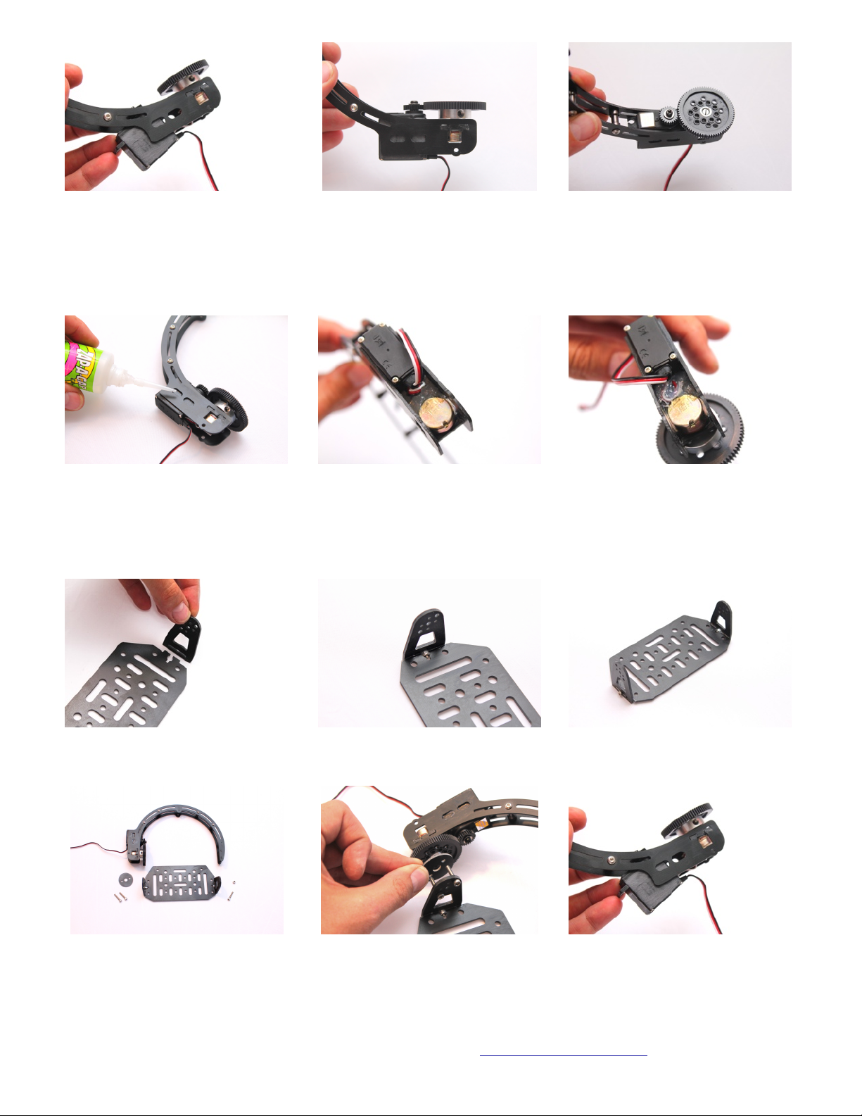
Install four rubber grommets into the large holes in the top of the landing skids as shown.
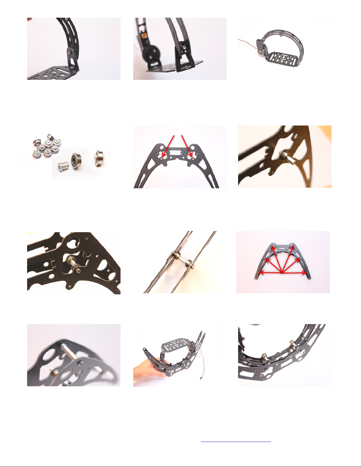
Install the landing skid tubes through the
landing gear legs and secure with the
rubber stoppers. You may need to slightly
files the holes of the skid legs to get the
tubes to slide through.
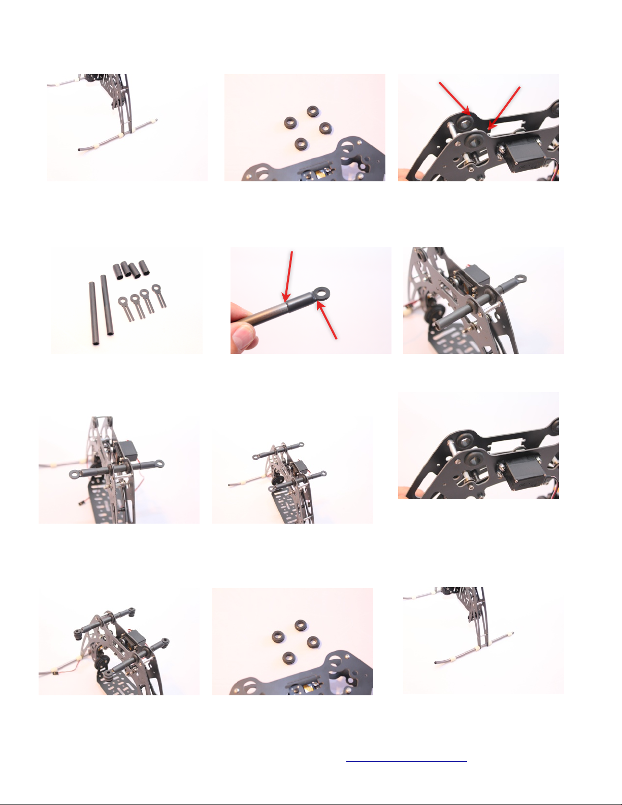
Two carbon tubes, four end fittings and
four pieces of adhesive lined heat shrink
are used in the next steps. The end fittings
may require sanding of the edges to snugly
fit into the carbon tube without splitting it.
Slip a piece of heatshrink over the end and
heat with heat gun or butane lighter. Heat
enough so the adhesive inside the heat
shrink tube begins to show at the ends.
Repeat the process of installing the other
ends on the carbon tubes with heat shrink.
BE SURE BOTH ENDS ARE ALIGNED
WITH EACH OTHER.
Now slide each carbon tube through the
grommets as shown.
When complete the assembly will look like
this.
Install the isolators on the carbon tube
ends. Orient them facing downward as
shown.
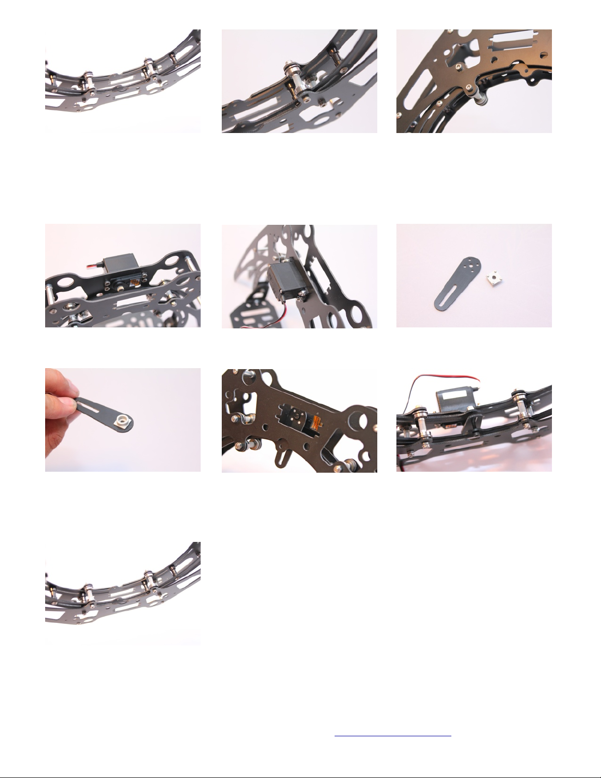
Now you will install the rubber ball mount
isolators. For cameras over 500gr. You may
fill the inside of the isolators with clear
silicone adhesive. Doing so will double the
weight capacity of the isolators.
Next install the battery tray plates onto the
opposite end of the rubber ball mounts.
Both battery tray plates shown installed.

10 Copyright © 2010 PhotoShip One LLC - www.PhotoShipOne.com
Now install the four long threaded spacers
onto the battery tray plates. These are the
spacers that will mount to the MK frame.
Use M3x6 screws.
This is a representation of the lower MK
Hex frame mounted to the top of the
mkTR gimbal.
This concludes assembly of the mkTR two axis camera mount. Thanks for your business with PhotoShip One.

11 Copyright © 2010 PhotoShip One LLC - www.PhotoShipOne.com
Description
QTY
G10 pieces
10
78t tilt gear
1
5k Potentiometer
1
6mm Hub/Set Screw
1
23mm threaded spacers
6
15mm threaded hex spacers
4
27mm threaded spacers
4
M3x6 button screws
26
M3x8 button screws
4
M3x10 cap screws
8
M3 nuts
10
M3x12 cap screws
8
M3x14 cap screws
4
Flange bearings & spacers
8
8mm threaded Hex
4
20t Servo gear
1
DS16FCD servo
2
Roll servo horn & hub
1
M3x22 screw
1
Landing skids
2
Skid stoppers
8
Rubber grommets
4
4” carbon .375” tubes
2
Carbon tube ends
4
.375” heat shrink
4
Ball mounts
4
Battery tray plates
2
Kit Parts Included (Some extra parts will remain)

12 Copyright © 2010 PhotoShip One LLC - www.PhotoShipOne.com
NOTICE OF REVISION
e mkTR v2 has an enhanced landing leg system that is removable to more easily facilitate replacement of broken skid
legs due to crashes or to allow for use of other landing legs. e previous version (mkTR v1) did not have removable skid
legs. e instruction manual shows photos and assembly instructions for mkTR v1, but the photos below show the new
style landing skid legs for v2. Disregard instructions in the manual that show v1 assembly and refer to this page for v2
skid leg assembly.
e landing gear support bridge is tapered. Be
sure to install the bridge between the skid legs
such that the wider portion is at the bottom
edge of the skids near the skid tubes.
Use CA glue or epoxy to secure the skid legs to
the bridge piece.
Be sure to readjust the roll/tilt arch bearings for
proper roll motion.
Table of contents
Other PhotoShip One Camera Accessories manuals
Popular Camera Accessories manuals by other brands

Riwall PRO
Riwall PRO RAB 240 Translation of the original instructions

agno's
agno's Jumbo MBS Plus quick guide

Selectronic
Selectronic SelectCell Ultimate 280 Series instruction manual

Lithionics Battery
Lithionics Battery GT Series installation manual

Ikelite
Ikelite 71722 instruction manual

MODSTER
MODSTER Whiteline User manual and safety instruction