Selectronic SelectCell Ultimate 280 Series User manual


SelectCell Manual

3
SelectCell Manual
Revision
Control
03 22/07/2021
14/11/2022
REV. DATE REASON / RESPONSIBLE
Revision Warnings
04 08/04/2022 Manager - Worker
05 Review of new PCC/PCM codes
Limitation of Warranty and Liability
The limitation of warranties and liabilities as per SelectCell full warranty terms and conditions described
in the product warranty document.
The information included in this manual has been written for the purpose of providing the user with
more detail and clarity in terms of content. Nonetheless, Selectronic Australia reserves the right to
modify the contents of this manual through future revisions at any time and without prior notice.
Confidentiality
All information provided by Selectronic Australia by virtue of this User Manual and any data or
features that may be disclosed by such shall be completely confidential and may not be shared with
third parties or used for purposes other than that for which is was intended without prior and express
written authorization from Selectronic Australia.
Limitations on the use of this equipment
This equipment may not be used in applications for recharging electric vehicles. Selectronic
Australia shall not be held liable for use with these types of application. The buyer shall be wholly
responsible.
Contact
Selectronic Australia
80 Lewis Road
Wantirna South Vic 3152
Australia
Tel. +61 3 9727 6600
Technical Support:
www.selectronic.com.au/support

4
SelectCell Manual
Contents
1 Introduction .............................................................................................................................. 06
1.1 Purpose ............................................................................................................................ 06
1.2 Acronyms .......................................................................................................................... 06
2 Safety .......................................................................................................................................... 07
2.1 General information ........................................................................................................ 08
2.2 Safety Instructions– Potential hazards ...................................................................... 08
2.3 Electrical safety .............................................................................................................. 08
2.4 Mechanical safety ........................................................................................................... 09
2.5 User requirements .......................................................................................................... 09
2.6 Lockout-tagout of machines and installations (L.O.T.O) ....................................... 09
2.7 Switching, measurements and checks ..................................................................... 10
3 General description ................................................................................................................ 10
4 Specifications .......................................................................................................................... 11
4.1 Summary ........................................................................................................................... 11
4.2 11
11
eBick PRO 280 Series ...................................................................................................
4.2.1 Physical characteristics ...............................................................................
4.2.2 Electrical characteristics .............................................................................. 11
4.3 12
12
PCC SERIES 150V 300A / 500A ..................................................................................
4.3.1 Physical characteristics ...............................................................................
4.3.2 Electrical characteristics ............................................................................... 12
4.4 12
12
PCC SERIES 800V 300A ................................................................................................
4.4.1 Physical characteristics ...............................................................................
4.4.2 Electrical characteristics .............................................................................. 13
4.5 13
13
PCM SERIES SLAVE ....................................................................................................
4.5.1 Physical characteristics ...............................................................................
4.5.2 Electrical characteristics ............................................................................. 14
4.6 14
14
PCC SERIES 150V 300A / 500A SLAVE ...................................................................
4.6.1 Physical characteristics ...............................................................................
4.6.2 Electrical characteristics ............................................................................. 14
4.7 14
PCM MASTER C/CAN .....................................................................................................
4.7.1 Physical characteristics ............................................................................... 14
4.8 15PCM MASTER S/CAN ....................................................................................................
4.8.1 Physical characteristics ............................................................................... 15
4.9 15
15
PCC MASTER ..................................................................................................................
4.9.1 Physical characteristics ...............................................................................
4.9.2 Electrical characteristics ............................................................................. 15
4.10 Hardware ............................................................................................................................ 15
4.10.1 Battery module ................................................................................................ 15
4.10.2 PCC ................................................................................................................... 16
4.10.3 PCM .................................................................................................................. 16
4.10.4 Master Busbar Cabinet ................................................................................. 16
5 Operating modes and processes ....................................................................................... 17
5.1 State machine .................................................................................................................. 17
5.2 Start-up and shut-down processes .......................................................................... 18
5.3 Connection process ....................................................................................................... 18
5.4 Ultra-low consumption mode ...................................................................................... 18
5.5 Pre-charge process ....................................................................................................... 19
5.6 Passive equalisation ....................................................................................................... 19
6 System monitoring .................................................................................................................. 20
6.1 State of Charge (SoC) calculation ............................................................................... 20
6.2 Ideal charging conditions ............................................................................................... 20
6.3 State of Function (SoF) and nal battery use ........................................................... 21

5
SelectCell Manual
6.4 Calculation of battery integrity (SoH) .......................................................................... 21
6.5 Extending battery life and end use ............................................................................. 21
7 Electrical safeguards .............................................................................................................. 21
7.1 Parameters involved in the protection functions ..................................................... 21
7.2 Reclose ............................................................................................................................. 22
7.3 Under-temperature .......................................................................................................... 22
7.4 Over-temperature ............................................................................................................. 22
7.5 Undervoltage .................................................................................................................... 22
7.6 Overvoltage ........................................................................................................................ 23
7.7 Temperature difference ................................................................................................... 23
7.8 Voltage difference ............................................................................................................ 23
7.9 PCC charge and discharge currents ............................................................................ 23
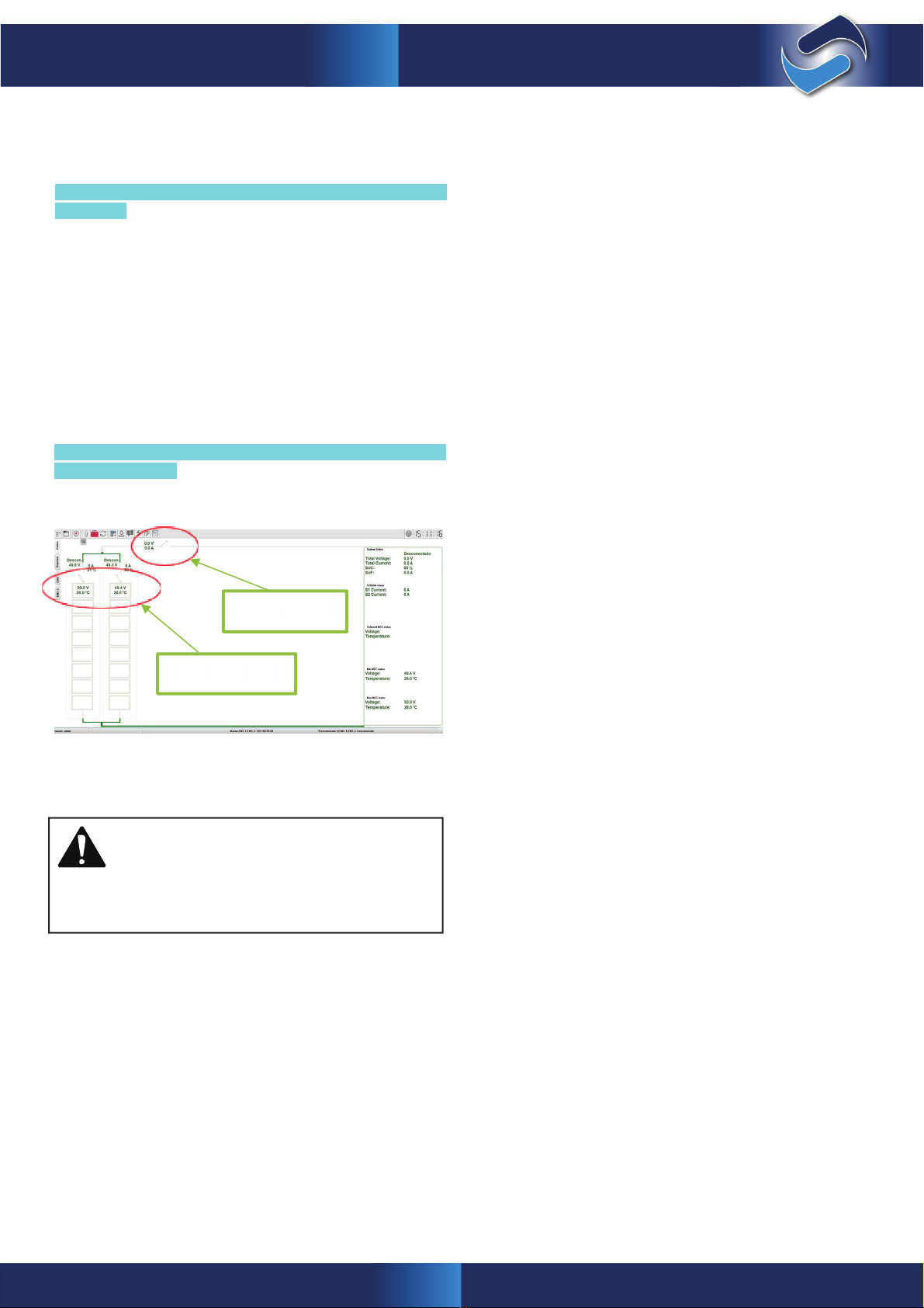
8 Data display ................................................................................................................................ 23
8.1 HMI display ........................................................................................................................ 24
8.2 Remote display ................................................................................................................. 25
8.3 Master Screen .................................................................................................................. 25
8.3.1 Contactor switching ....................................................................................... 26
8.3.2 Reset strings .................................................................................................... 26
9 Communications ...................................................................................................................... 27
9.1 IIntroduction ...................................................................................................................... 27
9.2 CAN protocol ....................................................................................................................... 27
9.3 Modbus protocol ................................................................................................................. 27
9.4 Type of data ......................................................................................................................... 27
10 Installation requirements and recommendations ......................................................... 28
10.1 Applicable regulations .................................................................................................... 28
10.1.1 Requirements for Electrical installations ................................................... 28
10.1.2 Requirements for Battery Installations ...................................................... 28
10.2 Environmental requirements ........................................................................................... 30
10.3 Maintenance and storage procedure .......................................................................... 30
10.4 Layout .................................................................................................................................. 30
11 Installation .................................................................................................................................. 30
11.1 Electrical and component verication ........................................................................ 30
11.2 Steps to follow .................................................................................................................. 31
11.3 Different possible congurations .................................................................................. 31
11.4 eBick installation .............................................................................................................. 31
11.5 Communication connections ........................................................................................ 32
11.5.1 Connections between batteries .................................................................. 32
11.5.2 Battery connections with PCC or PCM ..................................................... 33
11.6 Power connection ........................................................................................................... 33
11.6.1 Power connections between batteries ...................................................... 33
11.6.2 Battery connections with PCC or PCM .................................................... 35
11.7 Master/Slave systems ..................................................................................................... 37
11.7.1 PCM Slave and PCC Master system .......................................................... 37
11.7.2 PCC Slave and PCM Master system........................................................... 38
12 Transportation requirements and recommendations ................................................... 41
13 Maintenance plan ..................................................................................................................... 41
13.1 Predictive maintenance ................................................................................................. 41
13.1.1 Verifying voltages, warnings and alarms .................................................. 41
13.2 Preventive maintenance .................................................................................................. 41
13.2.1 Preventative maintenance schedule .......................................................... 41
13.3 Corrective maintenance ................................................................................................ 42
13.4 Maintenance requirements ........................................................................................... 42
6
SelectCell Manual
1.
Introduction
1.1
Purpose
The following document represents the complete manual for the installation, use and maintenance of the SelectCell energy
storage system, comprising SelectCell Ultimate 280 Series modules and PCC protection and control cabinet.
1.2 Acronyms
FAT
Factory
Acceptance
Tests
BMS
Battery
management
system
SelectCell Ultimate Series
Battery
pack
48V
280Ah
EMS
Energy
management
system
PCC
Power
Control
Cabinet
SoC
State
of
charge. Amount
of
energy
in
battery
State of function. Maximum admissible amount of charge or
discharge current at any moment
SoF
STRING
Cabinet
containing
various
modules
and
a
PCC
7
SelectCell Manual
2.
Safety
DANGER!
Always use the SelectCell Ultimate 280 module with a PCC protection and control
system. Never connect the module without the PCC.
To prevent high inrush currents, a bus pre-charge is required. A direct connection may result
in damage to the system. This pre-charge is managed from the PCC.
DANGER!
Check that the voltage is within range before connecting the equipment to the inverter.
NEVER connect the string if the voltage is out of range or NULL.
DANGER!
NEVER remove or bypass PCC switching and protection systems.
DANGER!
Do not short-circuit the current circuit terminals of the SelectCell Ultimate 280 module or the
PCC. The short-circuit current may be several thousand amperes. Prolonged short-circuiting
will destroy the battery module and electrolyte may leak out of the cells, causing a fire and/or
explosion.
DANGER!
SelectCell installation and maintenance personnel shall wear protective apparel, special
gloves and safety glasses. All personal metal objects such as wristwatches, rings, jewelry,
etc., shall NOT be worn while working with the SelectCell Ultimate 280 modules.
DANGER!
To avoid short-circuits and electric shock, use safety tools (EN 60900) and protection devices
when installing and servicing the equipment.
DANGER!
Do not connect or disconnect the load when the main contactor is closed. This may cause an
electric arc and expose personnel to high DC voltage. The electric arc might also destroy
connectors, due to a welding effect.
DANGER!
In case of fire, disconnect the circuit from the battery and use a CO2 extinguisher to extinguish
the fire. The batteries contain flammable materials. Always inform fire-fighters about the
lithium batteries.
DANGER!
Do not open the covers on the SelectCell Ultimate 280 modules. Do not place or drop
conductive objects inside the battery module or between the module’s terminals.
WARNING: RISK OF FIRE OR EXPLOSION
Failure to comply with safety messages may cause serious injury, death or damage to property
8
SelectCell Manual
DANGER!
Do not expose to temperatures above 65ºC. The equipment will not be operational beyond these
temperatures, however, even with non-operational equipment exposing the cells to high
temperatures may cause fire and/or explosion.
DANGER!
Do not immerse the SelectCell Ultimate 280 module in water or any other liquid.
DANGER!
Never drop or knock the SelectCell Ultimate 280 modules.
DANGER!
If chargers/converters are used, use only those authorised by Selectronic. Misuse of the battery
module during charging or discharging may cause the equipment to age prematurely leading to
fire and/or explosion. Both units have complex communications and these need to be carried
out by authorised specialists.
DANGER!
In the event of an emergency, read the MSDS (Material Safety Data Sheet) for the cells before
proceeding.
2.1 General information
The SelectCell Ultimate is a smart energy storage system with
Li-ion cells.
The whole system contains a high energy capacity. To minimize
the risk of electric shock, short-circuit, explosion and/or fire,
follow the relevant procedures and local guidelines, as well as
the instructions that are included with the system.
Only qualified personnel should perform the installation, in ac-
cordance with the applicable regulations. Systems with visible
electrical connections have to be isolated from public access.
For safety purposes, cover all direct connections and terminals.
Carefully read, understand and apply all requirements present-
ed in this section.
•
Do not use the module if any of its parts have been im-
mersed in water. A water damaged cell is potentially dan-
gerous. Any attempts to use the system could cause a fire
or an explosion. In such cases, contact Selectronic to have the
battery pack inspected.
•
The following instructions shall always be followed:
•
Any air inlet or outlet within the room shall be kept
clear and free of obstacles.
•
The floor shall be capable of bearing the weight of
all equipment, keeping in mind the weight of each
battery is 105kg.
•
There shall be no obvious signs of wear on any
STRING element.
•
As this is a battery, there is voltage on the cabinet’s
+/- output terminals whenever the PCC contactor is
closed.
2.2 Safety Instructions– Potential hazards
•
The area around the SelectCell Ultimate shall be kept
clear and free of combustible materials, gasoline and/or other
flammable fumes, vapours and liquids.
2.3 Electrical safety
•
Never remove safety guards or devices that protect against
live parts.
•
Do not reach inside the STRING or the modules, nor touch
any internal component.
•
Do not use or handle any SelectCell component when
accidentally wet, or with wet hands or feet.
•
In the event of a failure or incident, as a first step cut off the
current. To rescue a person being electrocuted, do not touch
them but immediately stop the current.
•
The area defined by safety margins for the necessary supply
and venting of air shall be respected.
In the event of an emergency, the SelectCell has electrical
safety cut-off elements (fuses and contactors). It is
advisable to install an element that protects against over-
current and possible short-circuiting. It is also advisable that
the cut-off element can be manually operated if necessary.
Remember, because this is a battery, the STRING’s internal
DC bus will always be live.
•
DANGER!
Battery terminals are live – DO NOT TOUCH. DO NOT BREAK UNDER LOAD.
+

9
SelectCell Manual
2.6
Lockout-tagout
of
machines
and installations
(L.O.T.O.)
To perform operations, absent of voltage (L.O.T.O.), the device
shall be locked and tagged to non-hazardous voltage values.
The following section is based on the lockout-tagout at several
points according to:
1.Restrict access to the work area to prevent entry of unauthor-
ised personnel.
2.It shall be disconnected and isolated from the supply network
or connection to the converter.
3.Once disconnected, the STRING shall be sectioned into parts
with voltages below 75 VDC.
4.The terminals of these parts shall be protected by insulating
caps designed for this purpose.
5.Given that the batteries are an energy storage system, it is
impossible to make certain points of the system free of volt-
age. If there is any exposed point where the voltage cannot be
eliminated, the terminals will have to be tagged, indicating the
voltage value at that point.
6.Prior to conducting any work, the voltage shall be measured
at the point where the work is to be done. Some points may
be energised directly from the batteries.
•
If it is not possible or takes too long to cut the current, try to
disengage them by means of an insulating element (wooden
strip or board, rope, wooden chair ...).
Whenever a battery is not installed on the STRING, make sure
that the power terminals at the front are protected against
accidental contact given that the terminals are energised.
Make sure that the output and input connection cables are not
short-circuited.
Make sure there is no short circuit between positive and neg-
ative terminals at any point.
Make sure there is always protective insulation on the output
and input cables and a reliable connection.
Never use cables that are visibly damaged or that may be
suspected of being damaged.
Minimise conductivity, avoiding surfaces in contact with wa-
ter. Hands and clothes have to be dry.
Do not use, install or store the system under wet or damp
conditions.
•
•
•
•
•
•
•
2.4
Mechanical
safety
•
Due to the weight of the battery modules (>100 kg), mechan-
ical means have to be employed to install them.
•
Do not stack SelectCell Ultimate modules more than 4 high.
•
•
Use only 600V insulated tools
If terminals are exposed during the sectioning process,
use 600V rated insulating gloves.
Use a face shield during the work.
Should it be necessary to perform an operation on a bat-
tery pack, place the modules on insulating matting.
Use insulating footwear.
To avoid possible short-circuiting, do not carry any con-
ductive device (e.g. pens, tape measures, etc.) during the
work.
Do not wear any metal, conductive or sharp edged
accessories.
2.5
User
requirements
In addition to personnel who work with the module, workplace
users should also implement safety measure by applying the
minimum provisions on the protection of the health and safety of
workers exposed to electrical risk in the workplace, refer to your
local jurisdiction.
Hazards related to electrical risk are specifically identified dur-
ing the work process with this equipment. This does not exclude
the possible existence of other risks present during handling and
use, such as overexertion, posture, or other measures against
health risks. Operators shall receive the necessary training,
sufficient to be able to prevent and avoid any risks arising from
use of the equipment.
By design the equipment protects against these risks under
normal operating conditions, however, it is with operations that
differ from normal ones (installation, maintenance, ...) where
special precautions have to be taken.
Particular care should be taken when handling modules, due
to their weight. Respect guidelines according to current regu-
lations regarding ergonomics in the. Use appropriate handling
equipment.
•
•
•
•
•

10
SelectCell Manual
2.7 Switching, measurements and checks
The regulation permits operations and interventions without
lockout-tagout, provided that an equivalent level of safety is
guaranteed.
These interventions are called switching, trials and checks. They
have to be carried out by authorised personnel with protection
devices and personal protective equipment appropriate for the
voltages in question.
Special protection against short-circuits should be ensured. In-
structions to follow:
•
No terminal with an electrical charge should be left uncov-
ered. If, after removing the connections, the terminals are
exposed, then they have to be protected with the terminal
covers supplied.
All tools shall be insulated and rated up to 600V
Operators shall not wear or carry any metal elements or de-
vices.
The work area shall be free of obstacles.
If necessary, when there are exposed terminals nylon slings
shall be used instead of chains.
The operator shall wear a face shield or safety glasses to pro-
tect against short-circuits
•
•
•
•
•
The operations shall
trained, personnel.
only be carried by authorised, duly
•
•
Safety apparel that covers the whole body (long sleeves) shall
be used. Fireproof or flame retardant, with protection against
chemicals and arc flash.
•
The work shall be done from a solid, stable support
•
If a work table is used, it shall be insulated or covered with
Insulating matting.
Occasionally, depending on the operation, there should be a
preventive resource worker present.
General description
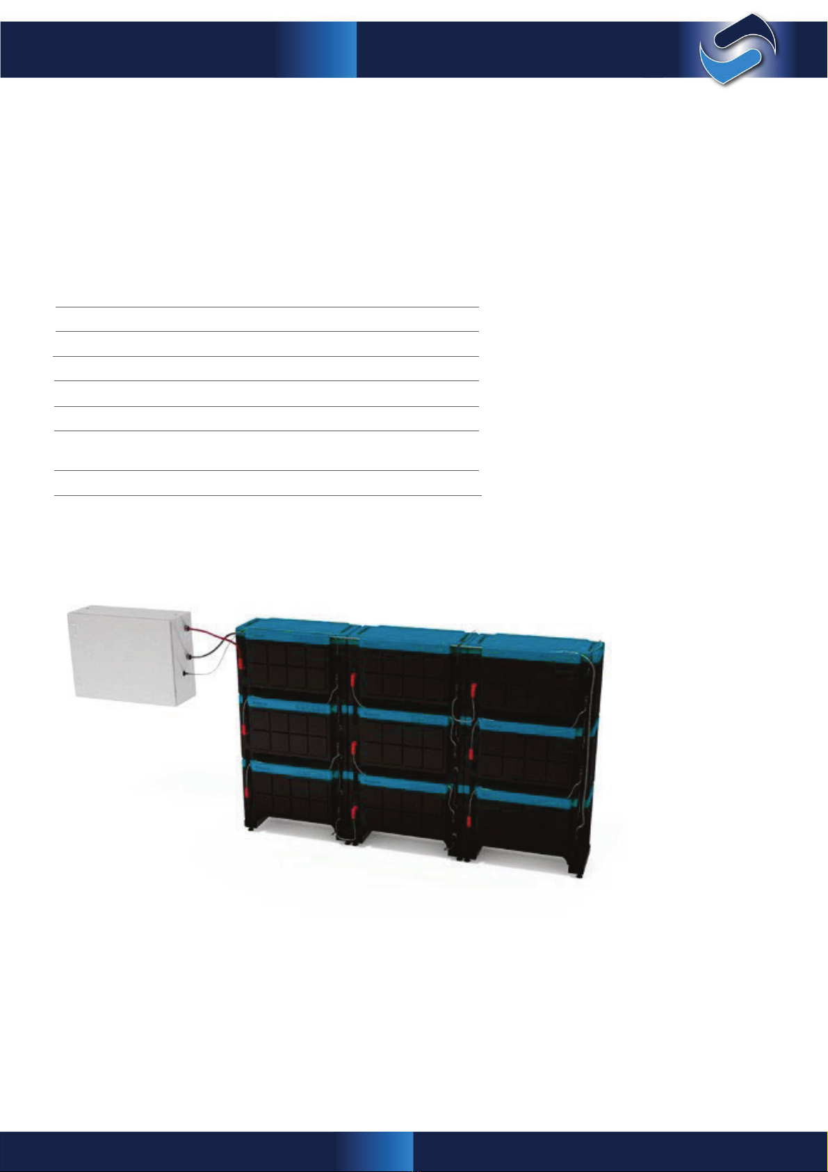
The Selectronic SelectCell Ultimate 280 Series is a lithium-ion
battery, 48VDC nominal and 280Ah capacity.
Each one of the modules or batteries comprises 15 x 3.2V cells
in series welded using laser technology. The voltage of each of
these cells and the temperature of the module is continuously
monitored by its own local card (BMS), developed by
Selectronic.
Each module is fitted with a 300A single-pole fuse, accessible
via a cover on the side of the module, enabling a quick change
in the event of electrical failure on the installation. See corrective
maintenance instruction in section 13.4.
The SelectCell Ultimate 280 Series modules can be connected
in Series in towers up to 3 high. In turn, each group of batteries
can be connected in parallel by using the Manager-Worker
configuration, making it possible to increase the system’s energy
and total power.
The system requires a PCC protection and control body in order
to operate. These control bodies contain the system’s protection
elements, as well as a card responsible for managing them
(EMS).
This EMS card acts as the Manager for the system, receiving all
the information from the BMS found in the system’s battery
modules via ISO SPI communications. To complete the
information needed, a reading of the current passing through the
circuit is made, as well as several voltage readings at string level.
Via an independent communications channel, the EMS also
manages the exchange of information with a higher order
system; be it an inverter, PC or SCADA. The EMS uses all of
this information to operate the protection systems, collect
statistical data and send critical information to external systems
(measurements, states, alarms, ...).
In turn, there is a system Manager in the Manager/Worker systems,
in charge of centralising the information from all of the Workers
and managing the opening of their respective contactors. This
equipment is the one that communicates with the inverter in
order to transmit both the necessary information and the
system’s alarms. This communication is done via the CAN or
Modbus TCP/IP protocol.
11
SelectCell Manual
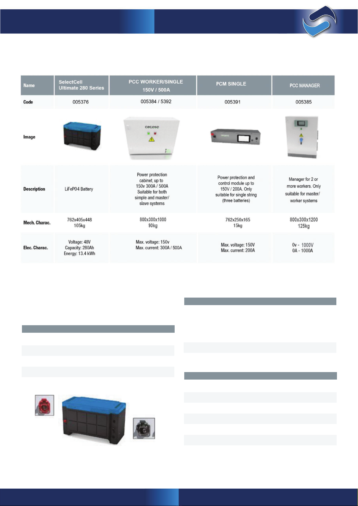
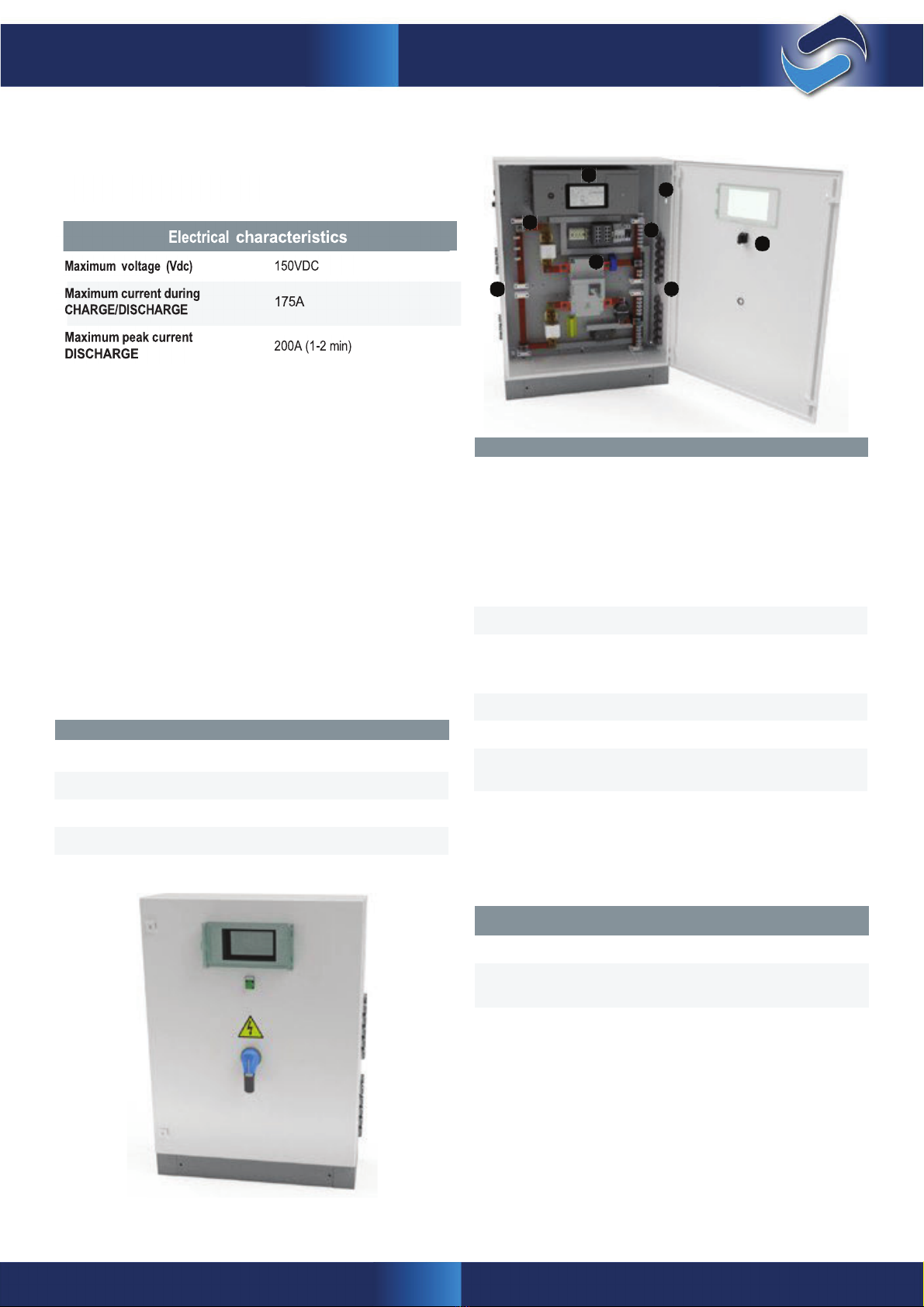
4. Specifications
4.1 Summary
4.2
SelectCell Ultimate 280
Series
4.2.1 Physical characteristics
The following table gives the specifications of the SelectCell
Ultimate 280 SERIES module:
The following table lists the SelectCell Ultimate 280
Series module interfaces, with a short description of each.
SelectCell Ultimate
Series module Interfaces
Power
Positive (1):
Left side of module
HARTING 1000VDCc 200A Fast
Connector
Negative (2):
Right side of module
Physical
characteristics
Height
448
mm
Depth
405
mm
4.2.1 Electrical characteristics
Electrical
specifications
Nominal volta
g
e
(
VDC
)
48
Maximum static voltage, SOC 100% (VDC)
52,2
Maximum current during charge/discharge: (A)*
200
Rated capacity (Ah)
280Ah
Rated energy (Kwh)
13,4
kWh
Nominal current during charge/discharge: (A)*
<140
Minimum static voltage, SOC 0% (VDC)
42
Weight
§k
g
Width
762
mm
Communications
2 Fast Connectors RJ45 Right side
(3)
12
SelectCell Manual
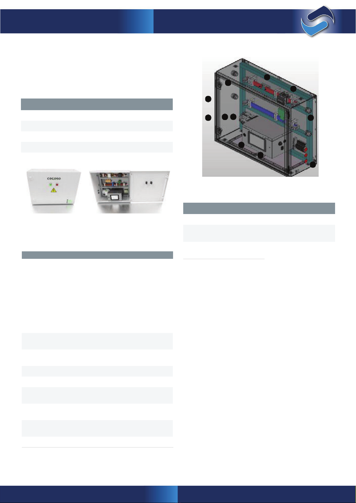
4.3 PCC WORKER / SINGLE / 150V
4.3.1 Physical characteristics
The physical dimensions of PCC WORKER 150V / 500A are
as
following:
1
1
1
5
Height
1000mm
4
3
62
Depth
300mm
8
7
1
4.3.2 Electrical characteristics
Maximum voltage (Vdc)
150VDC
The following table lists the interfaces with a short description
of each.
Maximum peak current
DISCHARGE
600A (1-2 min)
PCC 150V / 500A Interfaces
Power
OUTPUT (1) - Left side of cabinet:
Depending on the number of outputs
needed;
Max cable 185mm
2
1 Output as standard
INPUT (2) - Right side of cabinet:
Depending on the number of inputs needed;
Minimum cable 50mm
2
4 inputs as standard
ULTRA-LOW MODE
breaker
(4)
Front panel for switching on after entering
ULTRA LOW MODE
Modbus/TCP
Communications (6)
RJ45 connector on left side of PCC;
non-crossover Cat5e SERIES cable
User access (8)
USB connector on the PCC
ISO
SPI
Communications
(10)
Female RJ45 connector for
SelectCell Ultimate
modules
on the right side; Own COM cable incl.
Contactor
On positive terminal
On and Error LED (9)
RED to show a system error on the PCC’s front
panel; GREEN system ON
Maximum current during
CHARGE/DISCHARGE
500A
Electrical
characteristics
Weight
~90
Kg
Width
800mm
Physical
characteristics
Fuse
On positive terminal 150VDC / 500A
continuous
HMI
(7)
Touch screen on the PCC
CAN communications
(5)
RJ45 connector on left side of PCC;
non-crossover Cat5e SERIES cable
13
SelectCell Manual
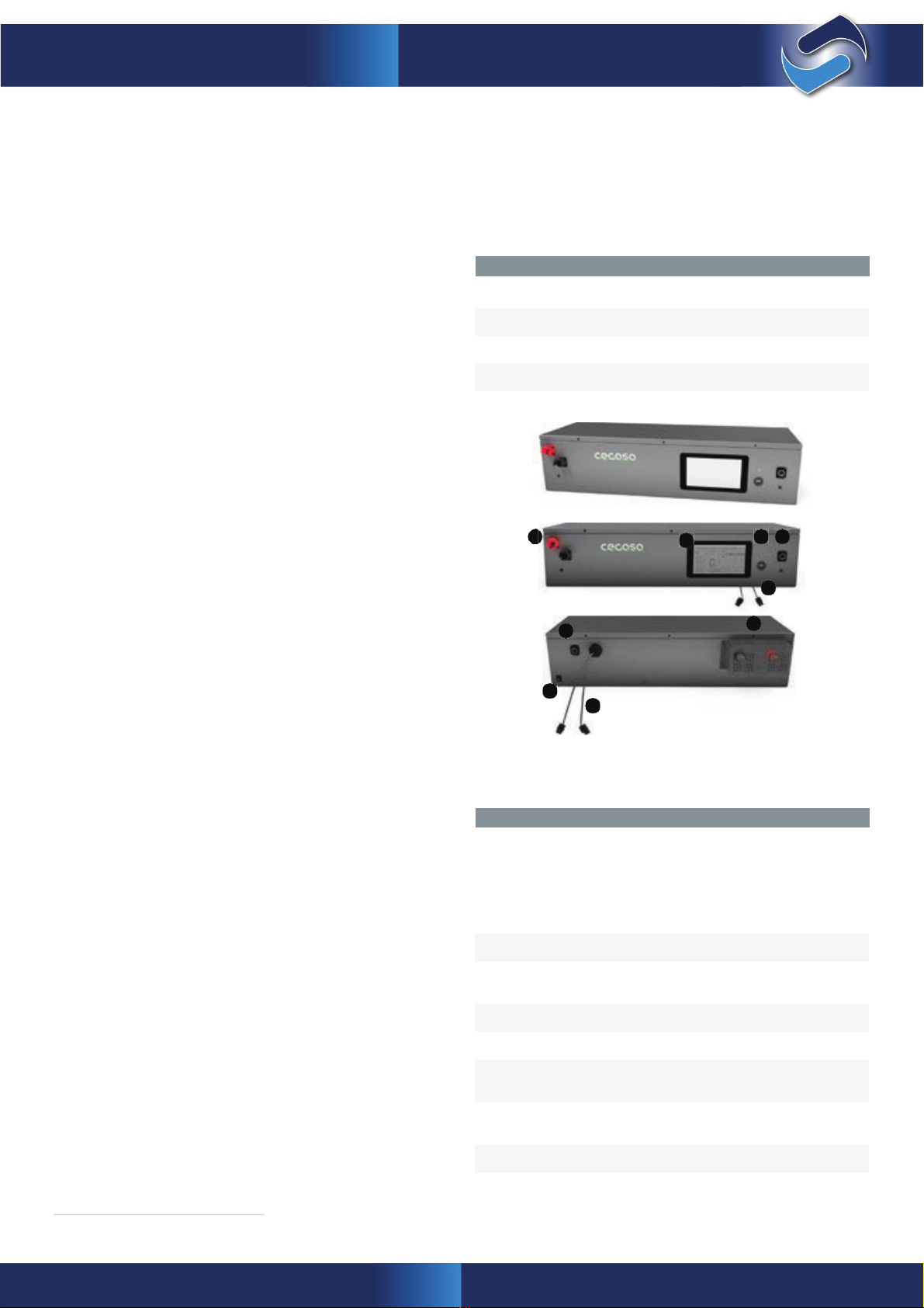
4.5
PCM SINGLE 200A
4.5.1 Physical characteristics
The physical dimensions of the PCM Single are as
follow:
Physical
characteristics
Height
165mm
Depth
250mm
2
7
8
5
6
1
4
3
9
The following table lists the interfaces with a short description
of each.
PCM 150V / 800V 200A Interfaces
11
1
12
5
Power
OUTPUT (1) – Back of equipment:
M12 cable gland; Minimum cable 50mm
2
INPUT (2) – Front of equipment:
Harting Han S connectors;
Minimum cable 50mm
2
62
8
7
Modbus/TCP
Communications (4)
RJ45 connector at the rear of PCM;
non-crossover Cat5e SERIES cable
10
User access (6)
USB connector on the PCM
ISO SPI Communications
(8)
Female RJ45 connector for SelectCell Ultimate
modules
on the front; Own COM cable included
Contactor
On positive terminal
24Vdc Bus (9)
24Vdc Bus to power the Manager’s electronics
Weight
§
Kg
Width
762mm
Error LED (7)
RED to show a system error on the PCM’s front
panel;
HMI
(5)
Touch screen on the PCM
ON/OFF switch (3)
Back panel for switching on/off
Notes:

14
SelectCell Manual
11
1
12
5
6
2
8
7
10
Notes:
15
SelectCell Manual
4.5.2 Electrical characteristics
5
8
63
7
4
12
PCC Manager 1000A Interfaces
Power
OUTPUT (1) –
Left
of equipment:
Bare wire terminal block;
Max cable 120mm
2
6 outputs standard
INPUT (2) – Right of equipment:
Bare wire terminal block;
Max. cable 185mm
2
4 inputs standard
4.9
PCC
MANAGER 1000A
4.9.1 Physical characteristics
The physical dimensions of the PCC Manager Busbar
Cabinet son Worker are as follow:
Internal switch used to connect communication
with workers. Detachable cable gland used
to pass cables inside the cabinet
Modbus/TCP
Communications (4)
Physical
characteristics
User access (6)
USB connector on the PCC
Height
1,300mm
Bus 24Vdc (8)
24Vdc Bus to power the manager’s
Depth
300mm
4.9.2 Electrical characteristics
Maximum voltage (Vdc)
1000V
4.10
Hardware
4.10.1
Battery module
Each battery module consists of:
•
Cells 3.2V – 280 Ah; forming a final array of 48V – 280 Ah
•
BMS: Card that takes the direct voltage reading for each one
of the cells and temperature reading for the module
•
Fuse: Each module has a fuse interposed between the cell
links. The acts in the event of an internal short-circuit or short-
Maximum current during
c
ontinuous Charge/Discharge
1000A
Electrical
characteristics
Weight
§120
Kg
Width
800mm
Error Led (7)
RED to show a system error on the PCC’s front
panel
HMI
(5)
Touch screen on the PCC
Door Isolator Switch (3)
Door Isolator sw
itch

16
SelectCell Manual
circuit on one of the modules’ terminals, opening the string
and preventing adjacent modules (depending on the position
data, acts on protection elements and communicates with
equipment at a higher level.
•
HMI: Touch screen, connected directly to the EMS. This
shows data on the state of the system, allowing manual
intervention if required.
•
Error LED: This LED flashes when the EMS detects a fault on
the system, whether it be an electrical or hardware fault.
•
Contactor: Safety element that cuts the current in the event
of the shorted module) from feeding
4.10.2 PCC
the fault
The protection module comprises the following elements:
•
EMS: This collects the data from all the BMS, manages these
data, acts on protection elements and communicates with
equipment at a higher level.
•
HMI: Touch screen, connected directly to the EMS. This
shows data on the state of the system, allowing manual
intervention if required.
•
Error LED: This LED flashes when the EMS detects a fault on
the system, whether it be an electrical or hardware fault.
•
On LED: This LED stays lit green when connected.
•
Contactor: Safety element that cuts the current in the event
of a system alarm. Located just before the protection
module’s output terminals, it is used to isolate the cabinet
before conditions that guarantee correct connection to the bus
are established, as well as protecting the string against
external faults.
•
Current transformer: Transformer that reads the system’s
total input and output currents to calculate the charge
remaining in the battery, as well as protection functions.
•
Power supply: One a stationary battery’s applications is
to be used as an uninterruptible power supply. To achieve this,
the electronics that manage the batteries cannot stop
receiving energy, so the only way to ensure this is to feed it off
the batteries themselves.
•
On/Off switch: Circuit breaker inside PCC used to start the
PCM once the power connections have been made. Should
the PCM have to be put out of operation, this switch is also
used to switch it off and isolate the electronics from the power
supply.
•
Power terminals: Access for the customer’s power cables is
located on the front of the module
of a system alarm. Located just before the protection
module’s output terminals, it is used to isolate the cabinet
before conditions that guarantee correct connection to the bus
are established, as well as protecting the string against
external faults.
•
Current transformer: Transformer that reads the system’s
total input and output currents to calculate the charge
remaining in the battery, as well as protection functions.
•
Power supply: One a stationary battery’s applications is
to be used as an uninterruptible power supply. To achieve this,
the electronics that manage the batteries cannot stop
receiving energy, so the only way to ensure this is to feed it off
the batteries themselves.
•
On/Off switch: Used to start the PCC once the power
connections have been made. Should the PCC have to be put
out of operation, this switch is also used to switch it off and
isolate the electronics from the power supply.
•
Breaker: In the event of entering ultralow mode this device
switches off the entire system to ensure there is no
consumption.
•
Power terminals: Access for the customer’s power cables is
located on the right side of the electric cabinet.
•
Communications connector:
Both
Communications
connectors are located on the back side of the PCM, identified
as “CANbus” and “Modbus”
•
Communications connector:
Both
Communications
connectors are located on the right side of the PCC, identified
as “CANbus” and “Modbus”
The Modbus/TCP connector uses a standard TCP cable.
The pinout for the CAN Communications cable can be
checked in chapter 9.2 CAN protocol. If a different pinout is
required, please contact Selectronic for assistance.
4.10.3 PCM
The protection module comprises the following elements:
•
EMS: This collects the data from all the BMS, manages these
17
SelectCell Manual
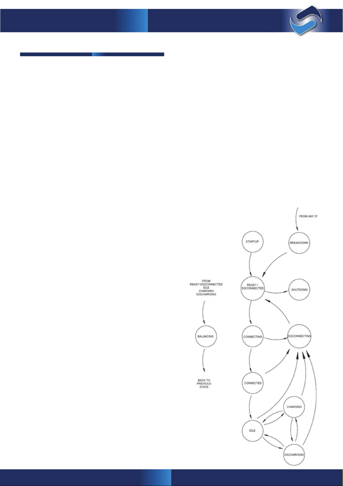
5. Operating modes and processes
5.1 State machine
The string is controlled by a sequential state machine. This state
machine is managed by the EMS located inside the PCC. The
user can check the state of the string both from the HMI and by
communications at address 0x3000 - 1 via CAN or at address
3001 via Modbus.
•
Discharging: Value at memory location = 35
In this state the current is being drawn from the string. The
SoC value will decrease proportionally to the current read
and the protection functions with the “discharge” suffix will
be enabled.
•
Disconnecting: Value at memory location = 6
Transition state. As soon as a disconnection command is
received or an error occurs during the connection sequence,
the system will change to this state as a step prior to open-
ing the contactor.
•
Breakdown: Value at memory location = 1
If the system experiences a critical fault (any error that
prevents safe use of the batteries), the EMS will change to
the Breakdown state, in which the contactor opens. It will
remain in this state until the errors are cleared, either via the
local HMI or by receiving a communications command to
reset errors.
•
Shutdown:
This state appears when a software reset is performed on
the EMS, either due to a settings change or a firmware
update. During this state, the EMS saves the system’s state
to memory, to continue under the same
conditions once the restart has finished.
The EMS state machine has the following states:
•
Start-up:
This starts the card, communications, and each of the BMS
located inside the battery packs. System settings anderror-
free check.
•
Ready / Disconnected:
Value at memory location = 2
Once the start-up sequence has finished, the system
remains in this state until the connection sequence starts,
whether due to a command, if the battery works together
with a manager or after a standby period, if the battery
works independently.
•
Eq Balancing: Value at memory location = 3
If the EMS detects that the charge difference between cells
is too high, and that system conditions are suitable for the
string to enter equalization, the EMS automatically orders
the equipment to this state. In this state any excess energy
in cells with the most charge will be dissipated until all the
cells have approximately the same stored energy.
•
Connecting: Value at memory location = 4
Transition state. the state machine changes to this state
once the connection command has been received and the
pre-charge has been performed (pre-charge is optional,
described in its own chapter). If the bus voltage reading is
correct, it orders the contactor to close and then changes to
the connected state.
If the voltage reading is not correct, the sequence is aborted
and it changes to the disconnecting state.
•
Connected: Value at memory location = 5
Transition state. After receiving the close command and
running the connection sequence, the string will have the
contactor closed. If no errors occur within a specific time, it
changes to the idle state.
•
Idle:
Value at memory location = 15
Once the string is connected, it remains in this state until a
through-current is detected. If the current value read has a
positive sign, it changes to the charging state, but if it is a
negative sign, then it changes to the discharging state.
•
Charging:
Value at memory location = 25
In this state the current is being fed to the string, so the SoC
value will grow proportionally to the current read and the
protection functions with the “charge” suffix will be enabled.
18
SelectCell Manual
To stop the system, via the touch screen, press the switch icon.
The string should never be switched off while current is flowing
through the system.
The contactor has to be opened from the screen (connect
button) prior to switching off the PCC.
5.3 Connection process
SelectCell Ultimate 280 systems can operate in 2 different ways:
Worker mode and Stand-alone mode
In Worker mode control depends on a higher level system, be
it SCADA, an inverter or operation personnel. In this mode, after
the system is started it remains in the ready/disconnected state
until it receives an external close command.
In stand-alone mode the system automates various opera-
tions, including direct connection. Once the SelectCell is started
in this mode, if no critical errors occur, the contactor will close
in- dependently. This mode is used together with inverters that
do not have communications, or whose communications system
is not suitable for controlling lithium battery pack switches.
The latter (stand-alone) is the default connection mode.
5.4 Ultra-low consumption mode
Should the batteries be left unattended for a prolonged peri- od,
the cabinet has an ultra-low consumption system to protect
them. If the equipment were to be left on without supervision
or use, the electronics in the batteries would consume their en-
ergy, so if the EMS detects a battery voltage value lower than a
desirable level, it follows a series of steps as the voltage de-
creases, until it switches the string off completely.
5.2 Start-up and shut-down processes
Please refer to the Installation Section page 28 prior to starting
the system.
Once the PCC is energized, the control electronics in the PCC
powers up. The EMS then checks hardware integrity (own
hardware and that of the BMS distributed by communications)
and that the cabinet distribution set-up corresponds with that
read. If no error is detected, the EMS allows work with batteries
to commence. The time required for start-up is less than 1
minute.
Prior to starting normal battery operation, it is advisable to
charge the modules up to 100% SoC.
In the case of the PCC, there is a circuit breaker to switch off
consumption definitively. To switch the equipment back on, it is
necessary to use the switch again. Contact Selectronic for
information on how to do this safely, because when the system
restarts there should be an energy source available to charge
the batteries (grid, generator, renewable...)
Input conditions for this ULTRA-LOW CONSUMPTION mode:
Current less than 2A AND minimum cell value <2975mV for 2h
The actions that occur are as follows:
DANGER:
ELECTRONICS SELF-CONSUMPTION
The electronics inside the cabinet are powered by
the batteries. If the batteries are not going to be used for a
prolonged period, the PCC has to be switched off.
Worker PCC
Contactor Switches
Manager PCC
Contactor Switch

19
SelectCell Manual
5.5 Pre-charge process
The pre-charge process is designed to be used with commercial
inverters. It requires specific custom-built hardware for this
application.
Power inverters, MPPT controllers and most of the power
electronics equipment work with a set of capacitors, coils and
transistors to modify the input signal to achieve the desired
output signal for the application.
To solve this problem, a DC bus soft-start is used.
In this instance, instead of initially closing the circuit with the
main contactor; an auxiliary contactor is used, which is con-
nected in series with a resistor that limits the current. This
resistor decreases the capacitors’ energization current and once
the DC bus is energized, the main contactor closes while this
auxiliary contactor is disconnected, as long as the bus pre-
charge has been done safely by reaching the desired bus
voltage level.
5.6 Passive equalisation
As the string charges and discharges, slight differences in the
chemistry of the cells produce different resistive values, leading
to differing losses during use of the battery and different
amounts of energy stored in each cell.
The end of the charging process is determined by the cell that
has the highest amount of stored energy in the whole string
(when a cell reaches 100% charge, the process stops regard-
less of the charge stored in the rest of the string’s cells), while
the end of the discharge process is determined by the cell with
the least amount of charge.
The differences in stored energy increase as the number of
cycles in the string increases; making the system increasingly
less efficient. To solve this problem, the EMS monitors the
difference between cells, initiating the equalisation process
whenever necessary.
Cell imbalance is due to different factors, the most common
being:
xDepth of Discharge (DoD): Higher DoD, greater im-
balance.
xCharge and discharge cycles: More cycles, greater
imbalance.
xOperating temperature: Working at temperatures
other than the optimum one produces greater
imbalance for the same charge/discharge cycle.
xCharge/discharge current: Higher currents, greater
imbalance.
The charge in a cell is partially related to the voltage in that
cell. SelectCell constantly controls the voltage in each of its
cells. If a high imbalance between cells is detected at any
point, then the EMS enters passive equalisation mode,
assuming the string is not being used.
During this process, any excess energy in cells with the
largest amount of charge is dissipated. By doing this, the
charge value of each cell begins to decrease slowly until each
cell reaches the charge value of the least charged cell.
There are two passive equalisation modes: Normal mode and
extreme mode.
A typical equalisation process, where a set of lithium-ion
cells with initially spread voltages is reduced over time as
the process is executed.
DANGER:
ULTRA-LOW CONSUMPTION MODE
If the user detects that the string has disconnected itself
and that the screen is off, charging battery should be
avoided.
If the battery tries to charge normally in this state; in the
best of cases, it would lead to a severe loss of capacity
for the equipment; in the worst case it would cause a
short circuit.
Under these conditions the battery has to be recharged
in a specific way.
Please contact Selectronic’s technical support department
so that it can analyse the situation and provide additional
instructions.
1. Contactor opens due to undervoltage
2. BMS switched off on each of the batteries
3. Screen and EMS switched off.
If the battery does reach any of these points it may still be
re- covered, however, it requires a specific charging method.
20
SelectCell Manual
6. System monitoring
6.1 State of Charge (SoC) calculation
One of the most important aspects in a battery is to know how
much stored energy remains in it, in order to determine how the
battery can be used.
This is quite simple with lead acid batteries, given that the sys-
tem voltage is practically proportional to the charge remaining in
the batteries.
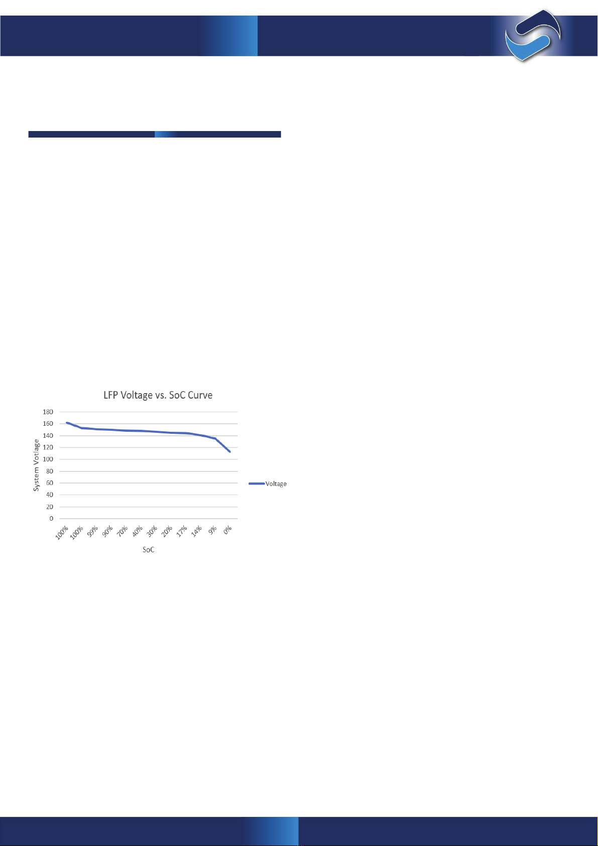
However, LFP-type batteries have a characteristic discharge
curve in which the voltage is flat for most of its utilization range,
and where a variation of 1-2 mV could represent a 10-20% er-
ror when estimating the charge. Only the voltage extremes vary
enough to be able to relate directly to the charge remaining in
the battery.
This, coupled with the fact that the shape of the characteris-
tic varies with different factors (discharge current, temperature
...), makes direct measurement of the voltage to represent the
charge remaining in the battery infeasible.
During most of the utilisation range the EMS continuously cal-
culates the batteries’ SoC using a coulometric based algorithm.
A reading is taken of the output current during discharge and
input current during charge, and the SoC is then updated by
adding or subtracting this energy.
An update of the estimated charge is performed at the ends of
the curve (0-20% and 95-100% charge), where the voltage can
be more precisely related to the remaining charge; updating the
SoC to this voltage under certain physical conditions.
•
100% update; given the SW defined voltage and current
conditions to interpret that the battery is fully charged.
Similarly, if one of the series reaches a value of 3575mV
for 10 seconds.
•
Idle update; The EMS electronics use their own algo-
rithms to update the SOC when idle (ZERO current after
a period of inactivity) depending on the voltage of cells
only within the range from 0 to 20%.
•
0-20% update based on discharge current; The EMS
electronics use their own algorithms to update the SOC
based on the discharge current of each module con-
nected in parallel and minimum cell voltage; this SOC
value is only updated with current within the range from
0 to 20%
6.2 Ideal charging conditions
The EMS system constantly controls the SOC conditions, tem-
perature, voltages of the entire system and uses communications
to send the inverters/chargers the optimum charge voltage and
charge current values in order to ensure correct control of the
charging process.
-Charge voltage based on cell temperature:
•
Between 0 and 5ºC
•
Between 6 and 10ºC
51.5V
52V
To solve this problem and attain a faithful representation of the
system’s state of charge, a mixed solution has been applied.
This manual suits for next models
1
Table of contents
Other Selectronic Camera Accessories manuals


