Phynix SURFIX PRO X User manual

Instruction Manual
New Functions
Surfix®Pro X


4. Calibration (1st menu item)
...
4.6 Combi-calibration
This calibration procedure combines zero setting and foil calibration in one single
command. When selected you are prompted to perform a zero calibration and, without
any further user interaction, a foil calibration. This procedure is useful for users who often
use both calibration methods.
Procedure:
1.
press this key; Calibration appears on the display
2.
press this key; Zero setting appears on the display
3.
press this key four times; Combi-calibration appears on the screen
4.
press this key; Place probe on “0” appears on the display, and the
ZERO symbol in the display begins to flash
5.
place the probe repeatedly perpendicular to the uncoated surface
of the test object
6.
press this key. Zero has been set appears briefly on the display.
Thereafter Place probe on foil standard appears on the display and
the CAL symbol in the display begins to flash.
7.
Put the calibration foil on the uncoated test object and place the
probe repeatedly on the foil
8.
press this key; set standard value appears on the display
9.
use the arrow keys to enter the calibration foil thickness as
indicated on the standard
10.
press this key; One-Foil-Calibration has been set appears briefly on the
display followed by the start screen with the four dashes ––––. The
CAL symbol is visable permanently.
You can now measure using zero calibration together with foil calibration.
...

4.7 Deletion of calibration
...
4.8 Set new probe zero
As you have read before, a normal zero calibration ( ) reduces measurement errors
induced by surface geometry e.g. by curved surface or near edges. During zero
calibration the gauge selects another calibration curve which fits better to the surface
geometry. Zero calibration is not useful for compensating errors induced by wear or
damage. In this case and if deviations are small the accuracy could probably be
increased by a function “set new probe zero”. This function determines a new zero value
for ferrous or non-ferrous mode by positioning the probe on a (preferrable new) PHYNIX
zero plate.
Attention: This functions alters the properties of the probe; if you are in doubt contact
your dealer or the manufacturer PHYNIX.
Procedure:
1.
press this key; Calibration appears on the display
2.
press this key; Zero setting appears on the display
3.
press this key; Set new probe zero appears on the display
4.
press this key; Modify probe data? appears on the display
5.
press this key, if you are sure to alter the probe properties. The ZERO
symbol in the display begins to flash, and Place probe on zero
appears on the display.
6.
place the probe repeatedly perpendicular to a (preferrable new) zero
plate; choose the zero plate type (Fe or Al) according to the
measurement mode you want to improve.
7.
press this key, if you are sure; Probe zero has been set appears briefly
on the display followed by the start screen with the four dashes ––––.
8.
if you are not sure, press this key to leave the calibration procedure;
you will get back to the menu .
...
4.9 Measurement
...

6. Measuring mode (3rd menu item)
...
6.5 SSPC PA2 mode
SSPC PA2 is a standard developed by the Society for Protective Coatings (SSPC) and
describes a procedure for determining conformance to a specified coating dry film
thickness on ferrous and non-ferrous metal substrates using nondestructive coating
thickness gauges described in ASTM D 7091.
The SSPC PA2 mode is a convenient way to measure coating thickness according the
SSPC standard. It can be selected under the menu item “Measuring mode”. It is
indicated by “PA2” in the display.
In fact SSPC PA2 mode is a kind of block value statistics, with a fixed block size of three
values. During measurement all three values of the actual block are shown on the real
time display. Additionally the moving average for this block and the mean value of all
already completed blocks are shown.
At the beginning of each block the first reading is displayed in the center of the display,
after the second measurement the actual reading is displayed there, and the first
reading moves one line down, indiacated by n1. Finally after the third measure¬ment the
last reading is shown in the center, and the two readings before are shown below,
indicated by n1 and n2. On the right side of the display x¯ shows the moving average of
the actual block, and x¯ t the mean value of all blocks.
6.5.1 Activating the SSPC PA2 mode
Procedure:
1.
press this key three times until Measuring mode appears on the
display
2.
press this key; Autom. Detection FN, F, N appears on the display
3.
press this key twice; SSPC PA2 mode appears on the display
4.
press this key; SSPC PA2 mode deactivate appears on the display
5.
press this key; SSPC PA2 mode activate appears on the display.
6.
press this key; SSPC PA2 mode activated appears on the display. As
indicator the PA2 symbol appears on the display.

Now a kind of block value statistics with fixed block size of 3 is established. After the first
measurement the display shows the coating thickness value with large numerals; after
the second measurement this value moves to the next line, indicated with “n1”. The
second reading is shown as usual. After the last, third measurment the display shows the
actual reading, the two former readings (indicated with “n1” and “n2”), the mean value
of this block x¯ , and at least the mean value of all blocks with x¯ t.
6.5.2 Deactivating the SSPC PA2 mode
Procedure:
1.
press this key three times until Measuring mode appears on the
display
2.
press this key; Autom. Detection FN, F, N appears on the display
3.
press this key twice; SSPC PA2 mode appears on the display
4.
press this key; SSPC PA2 mode activate appears on the display
5.
press this key; SSPC PA2 mode deactivate appears on the display.
6.
press this key; SSPC PA2 mode deactivated appears on the display.
The PA2 symbol disappears.
6.6 IMO PSPC mode
Measurements according the 90/10 practice refer to the “Performance Standard for
Protective Coatings” developed by the International Maritime Organization (IMO).
In this standard the 90/10 practice is defined. It means that 90% of all thickness
measurements shall be greater than or equal to a pre-defined nominal dry film thickness
(NDFT) and none of the remaining 10% measurements shall be below 90% of NDFT.

The IMO PSPC 90/10 mode supports the user applying the 90/10 rule. It can be selected
under the menu item “Measuring mode”. This mode is indicated by “90/10” in the display.
In 90/10 mode the gauge determines after each measuremet whether both conditions of
the rule are fulfilled. In this case the display shows “GOOD”. Otherwise if one or both
conditions are not fulfilled it shows “FAILED”. The procedure is as follows: After selection of
the IMO PSPC 90/10 mode you first have to set the nominal dry film thickness by means of
the arrow keys (setting) and the OK key (confirming). Subsequently the display shows five
values: the NDFT and the number of readings greater than or equal to this value; the line
below shows the thickness value (0.9 x NDFT) as well as the number of thickness values
lying between (0.9 x NDFT) and NDFT. At the left side of the display the total number of
readings N can be seen.
If only condition 1 (more than 10 % of readings are lower than NDFT) is not fulfilled it is still
possible to achieve a “GOOD” measurment series. Therefore the number of readings
higher than NDFT have to be increased. If condition 2 (none of the measurements should
be below 0.9 x NDFT) is not fulfilled it is no more possible to achieve a “GOOD”
measurment series. You can recognize this situation if the total amount of readings (N; left
side) is higher than the sum of both amounts (NDFT, 90%; right side).
6.6.1 Activating the IMO PSPC mode
Procedure:
1.
press this key three times until Measuring mode appears on the
display
2.
press this key; Autom. Detection FN, F, N appears on the display
3.
press this key once; IMO PSPC 90/10 mode appears on the display
4.
press this key; IMO PSPC 90/10 mode deactivate appears on the
display
5.
press this key; IMO PSPC 90/10 mode activate appears on the
display.
6.
press this key; Set nominal dry film thickness appears on the display.
7.
use these keys to adjust the nominal dry film thickness; with
continued pressing of these keys the set value increases or
decreases faster
8.
press this key; IMO PSPC 90/10 mode activated appears briefly on
the display followed by the start screen with the four dashes ––––.
As indicator the 90/10 symbol appears on the display. Also the
nominal dry film thickness (ndft) as well as 90 % of ndft are shown.

Now a kind of limit function is established. After each measurement the display shows the
nominal dry film thickness (ndft) followed by the number of readings above this value;
also the value “90 % of ndft” is shown, followed by the number of readings below this
value. On the left side of the display the total number of readings is shown. The result of
the measurement series is shown above the reading: if both conditions are fulfilled, the
display shows GOOD, otherwise FAIL.
6.6.2 Deactivating the IMO PSPC mode
Procedure:
1.
press this key three times until Measuring mode appears on the
display
2.
press this key; Autom. Detection FN, F, N appears on the display
3.
press this key once; IMO PSPC 90/10 mode appears on the display
4.
press this key; IMO PSPC 90/10 mode activate appears on the
display
5.
press this key; IMO PSPC 90/10 mode deactivate appears on the
display.
6.
press this key; IMO PSPC 90/10 mode deactivated appears on the
display. The 90/10 symbol disappears.
...

9. Options
...
9.7 Keylock
This function can help to prevent unintentional operation. After activation all keys
(except Power On ) are locked until the ESC key is pressed for 5 seconds.
9.7.1 Activating the Keylock
Procedure:
1.
press this key twice; Options appears on the display
2.
press this key; Switch-off mode appears on the display
3.
press this key twice; Keylock appears on the display
4.
press this key; Switch on keylock? appears on the display
5.
press this key for confirmation; To unlock press ESC key 5 sec.
appears briefly on the display, followed by the start screen with the
four dashes ––––.
Now the keylock is activated. No user interaction is possible, pressing a key will result in a
double-beep. Only switch-off is possible, but it will not finish the keylock.
9.7.2 Deactivating the Keylock
Procedure:
1.
press this key for appr. 5 seconds; a longer lasting beep will indicate
the deactivation of the keylock.
9.8 Selecting the language
...

EIN-Folien
EIN-Folien
Kalibrierung 2/6
Surfix menu structure
® Pro X
Two-foil
calibration 3/7 Set 1st standard value Place probe on
2nd foil standard
Zero setting
1/7
One-foil
calibration 2/7
Set standard value
Zero has been set
Calibration has been set
Set standard value
Calibration has been set
Deletion of
calibration 6/7
Place probe on
1st foil standard
Place probe on "0"
Place probe on
foil standard
Place probe on
coating
Works calibration
activated
Transfer of
statistics 1/8
Display of
statistics 3/8
Single-value/block-value
statistics 6/8
Single val.stat.
switch on 1/2
Single val.stat.
switched on
Set block size
Block val.stat.
switch on 2/2
Set lower limit
Deletion of
limits 2/2
Set upper limit
Limits deleted
Limits
2/6
Limits have been set
Limits setting
1/2
Autom. detection
FN, F. N 1/6 Automatic
identification (FN) 1/3
Ferrous (F)
2/3
Non-Ferrous (N)
3/3
Measuring mode
FN selected
Measuring mode
F selected
Measuring mode
N selected
Conti-mode
deactivate 1/3
Conti-mode
deactivated
Transfer of statistics
and readings 2/8
Deletion of statistics
and readings 5/8
Display of
readings 4/8
Conti-mode with
stable values 2/3
Conti-mode with stable
values activated
Place probe on
foil standard
Cal-Through-Coat
calibration 4/7
Continious
mode 3/6
Conti-mode with
all values 3/3
Conti-mode with all
values activated
Set 2nd standard value
Zero offset
4/4
Zero offset
setting 1/2 Set zero offset value Zero offset set
Deletion of
zero offset 2/2 Zero offset deleted
Calibration
1/6
Statistics
2/6
Measuring mode
3/6
Block val.stat.
switched on
Trend
7/8
Histogram
8/8
Zero offset
4/6
Zero offset
setting 1/2 Set zero offset value Zero offset set
Deletion of
zero offset 2/2 Zero offset deleted
SSPC PA2 mode
5/6
SSPC PA2 mode
deactivate 1/2 SSPC PA2 mode
deactivate
SSPC PA2 mode
activate 2/2 SSPC PA2 mode
activated
IMO PSPC 90/10
mode 6/6
IMO PSPC 90/10
mode deactivate 1/2
IMO PSPC 90/10
mode deactivated
IMO PSPC 90/10
mode activate 2/2 IMO PSPC 90/10
mode activated
d
Set nominal dry
film thickness
Combi-
calibration 5/7 Place probe on
foil standard Set standard value
Place probe
on zero Calibration has been set
Set new probe zero
7/7
Place probe on zero
Probe zero has been set
Modify probe data?
Calibration has been set

Quick deletion of statistics
and readings
1. until "- - - -"
2.
3.
Power on/off
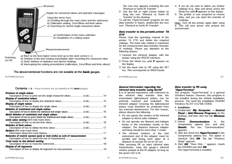
a) Scrolling through the menus
b) Setting of calibration, limit, offset values
c) Display of statistics and readings
a) Confirming of selected menu
b) Finishing an adjustment
a) Back to higher menu level
b) Deletion of the last reading immediate
after the measurement
d) Aborts an adjustment
c) Quick deletion of statistics and readings
d) Character selection during file name input
e) File selection
c) Confirming a character during file name input
d) Confirming a file name
f) Aborts file name input, if pressed longer
than 2 sec.
e) Deletes a character during file name input
+Total Reset
Switch-off mode
1/8
Auto switch-off
after 90 sec. 1/2
Permanent
operation 2/2
Auto switch-off after
90 sec. selected
Permanent
operation selected
Beeper
2/8
Beeper ON
1/2
Beeper OFF
2/2
Beeper switched ON
Beeper switched OFF
Measuring unit
3/8
Measuring unit
µm/mm 1/2
Measuring unit
mils 2/2
Measuring unit
µm/mm selected
Measuring unit
mils selected
Statistics and
readings 1/3
Statistics
2/3
Transfer content:
stat. + readings
Transfer content:
statistics
Readings
3/3
Transfer content:
readings
Send active file
1/4 In progress...
Select file
2/4
Select
File
Send all files
3/4 In progress...
File transfer
5/6
Transfer content
4/4
Welcome screen
4/8
Welcome screen
ON 1/2
Welcome screen
OFF 2/2
Welcome screen
switched ON
Language
8/8
English
1/3
Deutsch
2/3
Français
3/3
Keylock
7/8
Switch on keylock? To unlock
press ESC key 5 sec.
Options
6/6
Power supply
5/8
Batteries
1/2
Rechargeable
batteries 2/2
Power supply with
rechargeable batteries
Welcome screen
switched OFF
Power supply with
batteries
In progress...
Language English
selected
Sprache Deutsch
ausgewählt
Option langue
Français
Date + time
6/8
01-Jan-2010 00:00:00
Adjust? Set date + time
Close file
3/5
New file
1/5
Open file
2/5
Rename file
4/5 Rename file?
Delete file
5/5
File closed
Input file name
Select file
Input file name
Delete one
file 1/2
Delete all
files 2/2
Select file
Delete all files?
File: 1234ABCD
delete? File deleted
Using actual
calibration 1/2
Using works
calibration 2/2
Create file? File opened
File opened
File opened
File renamed
All files deleted
Data memory
4/6
g) Aborts key lock, if pressed longer
than 5 sec.

PHYNIX GmbH & Co. KG
Siemensstr. 14
D-41469 Neuss
Germany
Tel +49-2137-10978-0
Fax +49-2137-10978-28
www.phynix.com
© PHYNIX Germany E 05/2019 Art.Nr.: tbd.
Other manuals for SURFIX PRO X
1
Table of contents
Other Phynix Measuring Instrument manuals
Popular Measuring Instrument manuals by other brands

Extech Instruments
Extech Instruments EC100 user guide

FormFactor
FormFactor ACP40-GSG Series Quick reference guide

Anritsu
Anritsu MS2830A-040 Product brochure

Pittsburgh
Pittsburgh 63647 Owner's manual & safety instructions

SMC Networks
SMC Networks PFG3 0 Series Operation manual

Shakmat
Shakmat Bishop's miscellany Building Guide

Leica Geosystems
Leica Geosystems Rugby 840 quick start

Eclipse
Eclipse EGA2 Combustion instruction manual

Klein Tools
Klein Tools CL1200 instruction manual

TE
TE 4020 Operation manual

Ludlum Measurements
Ludlum Measurements 4525-2400 installation manual

Anaheim Scientific
Anaheim Scientific H400 instruction manual