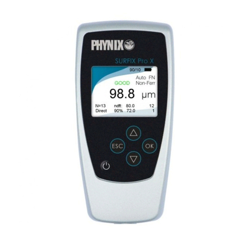
Phynix Surfix S User manual

© PHYNIX Germany
©PHYNIX Germany
- 2 -
- 4 -
The icon now appears including the text
'Shortcut to Surfix IR Transfer'
2. Use the left or right mouse button to
drag the icon 'Shortcut to Surfix IR
Transfer' to the desktop.
To call the "HyperTerminal" program for the
data transfer in future, double-click the new
icon: 'Shortcut to Surfix IR Transfer'.
Data transfer to the portable printer TA
210
Please read the operating manual of the
printer TA 210 and define the required
settings. The baud rate setting is important
for the measurement data transfer/transfer
of readings. Please pay attention to the
following actions:
1. Connect the infrared adapter with the
printer using the RS232 interface.
2. Press the Mode key until Fappears on
the display.
3. Set the baud rate to 96 using the SET
key. This corresponds to 9600 bauds.
©PHYNIX Germany
General information regarding the
infrared data transfer using Surfix®
It is of special importance with reference to
the infrared data transfer that the
transmitted light-induced pulses can be
perfectly received and evaluated. The
infrared adapter receiving the light-induced
pulses must therefore be protected from
any external interferences. For this reason,
please observe the following:
• Do not expose the window of the infrared
adapter to direct solar radiation.
• Do not operate any filament and halogen
lamps in the immediate vicinity of the
adapter. The distance between adapter
and lamp should be more than 1 meter.
• The infrared windows of the test
instrument and of the adapter must be
parallel and facing each other at a
distance of around 30 cm to 50 cm.
After pressing OK to start infrared data
transmission, keep the gauge´s infrared
window pointed at the IR adapter as long as
the green LED is lit.
©PHYNIX Germany
4. If you do not wish to define any further
settings (e.g. date and time), press the
Mode key until Pappears on the display.
5. The printer is now prepared to receive
data, and you can start the transfer of
readings.
Note: Turn off the printer again after using
it. This will save power and protect the
environment!
- 27 -
Data transfer to PC using
"HyperTerminal"
The program "HyperTerminal" is a general
Windows feature. However, this program is
not installed during the default installation
process. You need the installation CD-ROM
Windows 9x/NT 4.0/ME/2000.
• Installation
1. Double-click My Computer – Control
Panel – Add/Remove Programs on the
desktop, and then click the tab Windows
Setup.
2. Select Communications in the
Components options box, and click
Details. The box "Communications"
appears.
3. Click the check box HyperTerminal in the
Components options box. The option is
checked. Click OK. The tab "Windows
Setup" appears.
4. Click OK. "Have Disk..." appears. Insert
the CD-ROM and click OK.
The HyperTerminal is installed.
- 25 -
Using the arrow keys:
a) Scrolling through the main menu and the submenus
b) Calibration setting, Zero-Offset and limit values
c) Searching for stored single measured values
a) Confirmation of the menu selection
b) Completion of a setting action
a) Back to the next higher menu level up to the start screen (----)
b) Deletion of the last reading immediately after recording the measured value
c) Quick deletion of statistics and stored readings
d) Interrupting the setting procededure (calibration, Zero-Offset and limit values)
Switching
on/off
Displa
y
for numerical values and operator messa
g
es
IR
-
sensor
Measurement
-
sensor
The above-mentioned functions are not avaiable at the basic gauges.
Contents (n.b. = these functions are not available at the basic
g
au
g
es)
Printout of single values
Description of how to print out the single measured values ................ (n.b.) ................. 14
Display of statistical values
Description of how to display the statistical values ............................ (n.b.) ................. 15
Display of single values
Description of how to display the single values ................................. (n.b.) ................. 15
Deletion of statistical and single values
Description of how to delete the statistical and single values.................... (n.b.) ................. 16
Quick deletion of statistical and single values
Description of how to quick delete the statistical and single values ............ (n.b.) ................. 16
Limit value setting (3rd main menu item)
Description of how to set the limit values ........................................ (n.b.) ................. 16
Deletion of limit values
Description of how to delete the limit values .................................... (n.b.) ................. 17
Options (4th main menu item)
Information about the menu Options......................................................................... 17
Selection of metric system (µm) or inch (mils) as unit of measurement
Description of how to select the unit of measurement ................................................. 18
Total reset to the default setting
Description of how to reset the instrument................................................................ 18
Display of all segments
Description of how to display all segments for test purposes ........................................ 19

Using the gauge
© PHYNIX Germany
• HyperTerminal settings
1. Click Start – Programs – Accessories
– Communications, and click Hyper-
Terminal. The folder "HyperTerminal"
appears.
2. Double-click the icon Hyperterm.exe.
The box "Connection Description"
appears.
3. Specify the name, e.g. 'Surfix IR
Transfer'.
4. Select an icon by clicking one, e.g. 'open
book with phone', and click OK. The box
"Phone Number" appears.
5. Select and click in the options box
"Connect using" the option Direct to
COM 1 or Direct to COM 2. Click OK.
The box "COM 1 or COM 2 Properties"
appears.
©PHYNIX Germany
-- 28 -
6. Define the following port settings:
Bits per second: 9600
Data bits: 8
Parity: none
Stop bits: 1
Flow control: non
Click OK. "HyperTerminal" is activated.
7. Close 'Surfix IR Transfer –
HyperTerminal'. A question appears.
8. Answer the question: 'You are currently
connected. Are you sure you want to
disconnect now?' with Yes. Another
question appears.
9. Answer the question: 'Do you want to
save session Surfix IR Transfer?' with
Yes. The selected icon with the text
appears in the folder "HyperTerminal".
• Putting a Shortcut on the Desktop (if
required)
1. Use the right mouse button to click the
icon with Surfix IR Transfer. Click
Create Shortcut Here in the shortcut
menu then displayed.
- 26 -
© PHYNIX Germany
©PHYNIX Germany
- 1 -
- 3 -
OK
OK
OK
OK
OK
OK
OK
OK
On / Off
MENU
with arrow pads:
a) Browsing of the menus
b) Setting of calibriation and limits
c) Searching of stored readings
OK
a) Entering of the selected menu
b) Accepting the new calibration and limit values
ESC
a) Back to the higher menu level
b) Deletion of the last reading immediate after the measurement
d) Cancel of a current action (calibration and limit setting)
Options
4/4
Measuring unit
1/9
µm unit
mils unit
Auto FN identification
Ferrous (F)
Non-Ferrous (N)
Auto switch-off
Permanent operation
Backlight off
3 secs backlight
Permanent backlight
Switch-on
Switch-off
Mean and Standard Dev.
Maximum and Minimum
Switch-on
Switch-off
English
Francais
1/2
2/2
1/3
2/3
3/3
1/2
2/2
1/3
2/3
3/3
1/2
2/2
1/2
2/2
1/2
2/3
3/3
Welcome text
7/9
On-line statistics
6/9
Beeper
5/9
Backlight
4/9
Switch-off mode
3/9
Measuring mode
2/9
Calibration
Statistics
Limits
Zero setting
Foil calibration
Zero offset
MEN U
(Place probe on "0")
OK
(Place probe on foil standard)
(Works calibration activated)
Print-out statistics
Print-out of measurements
Display of statistics
Display of measurements
Deletion of statistics
1/5
2/5
3/5
4/5
5/5
1/4
2/4
Limits setting
Deletion of limits
1/2
2/2
Set lower limit
1/4
2/4
3/4
MENU
MENU
MENU
MENU
MENU
OK
OK
OK
OK
OK
OK
OK
OK
OK
OK
OK
OK
OK
OK
OK
OK
OK
OK
OK
OK
OK
OK
OK
OK
OK
OK
OK
OK
OK
OK
OK
OK
OK
OK
OK
OK
OK
Set upper limit
ESC
+
Total reset
3/4
Delete of calibration
4/4
OK
Offset setting
Deletion of offset
1/2
2/2
OK
OK
Batteries
Rechargeable Batteries
Deutsch
2/2
1/3
OK
1/2
2/2
OK
Language
8/9
Power supply
9/9
c) Deletion of the statistics (after the deletion of the last reading).
Function must be confirmed with OK
Pocket-Surfix Menu structure
®
Pocket-Surfix Software Version 2.0
Quick deletion of statistics
1. until "- - - -"
2.
3.
OK
ESC
ESC
Function not available for basic types
Measurement on flat areas
In order to open case use the screwdriver
included and lever off carefull
y
the upper
casin
g
part at the marked points (see also
instruction on page 8).
Measurement on c
y
lindrical ob
j
ect
Contents (n.b. = these functions are not available at the basic
g
au
g
es)
Typical applications
Specification of the equipment and examples of some layer combinations ...................... 7
Preparations for measurement
General information about start-up procedure and exchanging batteries ........................ 7
Menu structure
Information, (look page 1)....................................................................................... 8
Calibration and measurement (1st main menu item)
Information about calibration................................................................................... 9
Factory calibration
Description of how to activate the factory calibration .................................................. 9
One-point calibration (zero setting)
Description of how to carry out a one-point calibration ................................................ 10
Two-point calibration (using calibration foil)
Description of how to carry out a two-point calibration .......................(n.b.) ................. 10
Zero Offset Setting
This describes the setting of values for zero point suppression............(n.b.) ................. 11
Deleting Zero Offset
This describes how to delete the zero offset values ...........................(n.b.) ................. 12
Measurement
Information about the measurement and on how to select the method of measurement .. 12
Statistics (2st main menu item)
Information about statistics ...........................................................(n.b.) ................. 13
Printout of statistical values
Descri
p
tion of how to
p
rint out the statistics ....................................(n.
b
.) ................. 14

Introduction
The coating thickness gauge Pocket-Surfix®
(basic) has been designed and tested
according to DIN EN 61 010 Part 1, March
1994, Safety requirements for electrical
measuring, control and laboratory
equipment, and has left the manufacturing
works in technically perfectly safe condition.
In addition, the instrument conforms to the
standards for coating thickness
measurement:
Magnetic method DIN EN ISO 2178
ASTM B499
DIN 50 982
Eddy current method DIN EN ISO 2360
ASTM D1400
©PHYNIX Germany
To change the batteries, first remove the
screw on the back panel. Use the
screwdriver included to lever off upper
casing section at the marked points (see
page 28) in the circular casing slit. Keeping
both sections parallel, separate the upper
and lower parts with an up-and down
movement, carefully and without using
force.
After inserting the two batteries/
rechargeable batteries, reassemble the
casing by holding one section exactly over
the other, keeping the edges parallel, then
press both halves carefully together and
insert the screw.
NOTE: Please exchange the cells / storage
batteries within 20 seconds so that your
calibration and measurement data are not
deleted.
The instrument is switched on and off using
the ~key. When in the automatic switch-off
mode, the instrument will be automatically
switched off 1.5 minutes after the last
measurement or operation.
©PHYNIX Germany
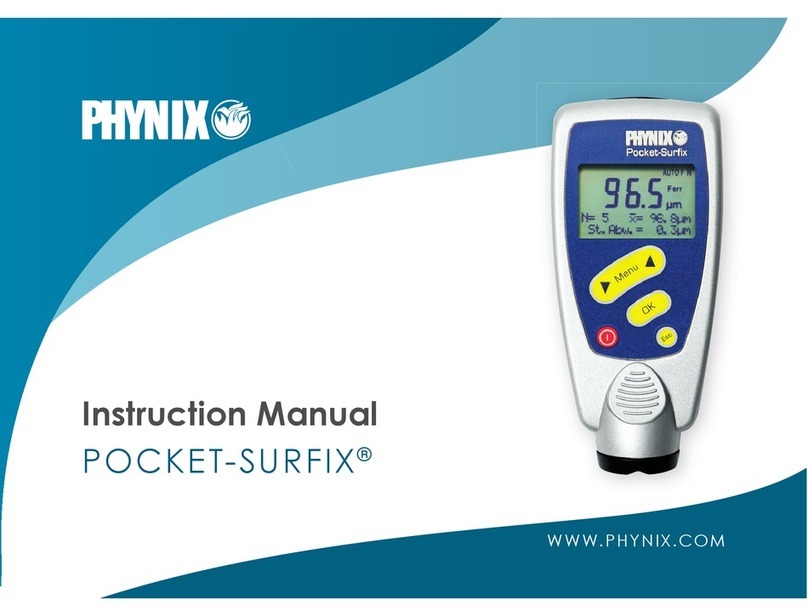
About this manual
It's the first time that the menu technique
which has already proved its worth a million
times on cellular phones is applied to the
operation of a coating thickness gauge.
This manual will inform you step by step on
how to correctly operate the Pocket-Surfix®
instrument. If you proceed according to
these step-by-step instructions, you will
already be able to carry out the first
measurements after only a few minutes.
- 6 -
Menu structure
The structure already described above is
mainly self-explanatory. The operation is
carried out in the same way as that of
commercially available mobile phones
(cellular phones). All there is to do to
activate a function is to take a look at the
menu structure in order to immediately
recognize the main menu item and the
subsequent submenu items to be called.
There are 4 main menu items: Calibration,
Statistics, Limit Values and Options. All
other menu items or functions are allocated
to one of these 4 menu items.
The steps to be carried out are each shown
on the display, e.g. "Place probe on the Cal
foil". The confirming messages are displayed
after these actions, e.g. "Calibration is
complete"
- 8 -
Memory
Max. 80 measured values, can be
recalled individually
Calibration
Factory calibration, zero setting or foil
calibration
Statistics
N, , s or N, Max, Min over max. 9.999
readings
Limit values
adjustable with acoustic control
Interface
Infrared, IrDA standard
Ambient temperature
0...50° C / 32°...122°F
Surface temperature of test object
max. 150°C /302°F (probe contact time
max. 2 sec.)
Power supply
2 x Micro (AAA) 1,5V or
2 x rechargeable batteries (AAA) 1,2V
Dimensions
Instrument: 99mm x 48mm x 24mm
4“ x 1.9“ x 0.96“
Probe: Inte
g
rated
©PHYNIX Germany
Probe is too close to metal:
The probe was too close to the metal during
switch-on. Hold the probe free in the air and
then switch the instrument on.
Magnetic interference fields:
Close to the probe are too strong magnetic
interference fields (e.g. transformers, PC-
display screens).
Probe defective:
If this error message appears, please send
the instrument to your supplier or to the
manufacturer for repair.
Other errors
If the following errors appear on your
instrument
• Instrument does not allow any further
measurements
• Illogical display values
a total reset usually helps (page 18)
©PHYNIX Germany
Measurement sensor: ∅5mm/0.2 dia.
Weight
Approx. 85g / 3ozs.
Protection class
IP 52
Specifications subject to change without notice.
Delivery schedule
Instrument with integrated probe
Soft carrying pouch with clip
Zero calibration standard(s) Fe (stainless)
and/or Al
2 calibration foils
2 batteries
Operating manual
Manufacturer´s Certificate
Optional accessoris
• Infrared adapter for standard PC
(RS232) and portable printer
NOTE: Integrated IR interfaces, such as
the ones in new notebooks, can not be
used.
• Portable data printer
• Calibration foils having different
thicknesses
- 23 -
• Keys have no more function:
please remove the batteries within 20
seconds. Insert the batteries again and
reset the instrument (total reset, page 16).
• Gauge cannot be switched on:
Disconnect batteries for a short time or
insert new batteries.
Maintenance / After-sales service
The Pocket-Surfix® instrument needs no
special maintenance. However, as every
gauge, it should be handled with care.
Please remove used batteries at once and
dispose of them in an environmentally
acceptable way.
Please send a damaged instrument or an
instrument showing faulty operation to your
dealer to be forwarded to us, or send it
directly to us.
- 21 -

©PHYNIX Germany
Technical data and product features
(not all available for basic gauges)
Instrument versions:
Pocket-Surfix®FN; Pocket-Surfix®FN basic
for measurements on steel/iron and
nonferrous metals (magnetic and eddy
current methods)
Pocket-Surfix®F; Pocket-Surfix®F basic
for measurements on steel / iron (magnetic
method)
Pocket-Surfix®N; Pocket-Surfix®N basic
for measurements on non-ferrous metal
Measuring range
0 ... 1500µm or
0 ... 60mils, unit is selectable
Resolution
0,1µm / 0.01mils or <2‰ of measured
value
©PHYNIX Germany
- 24 -
Tolerance referred to PHYNIX standards
- With works-calibration:
±(3µm/0.12mils or 3%) of reading
whichever is greater
(only on flat or slightly curved surface)
- After one-point calibration:
±(1µm/0.04mils +2%) of reading
- After two-point calibration:
±(1µm/0.04mils +1%) of reading
Display
Alphanumerical with 4 digits, digit height
10mm / 0.4”, with selectable backlight
Operator prompting
in the display in German, English or
French or optional language
Minimum measuring area
5mm x 5mm / 0.2“ x 0.2“
Minimum radius of curvature
convex: 3mm/0.12“,
concave: 30mm/1.2“
Minimum thickness of base material
Typ F: 0,5mm / 20mils,
Typ N: 50µm / 2mils
- 22 -
©PHYNIX Germany
Basic information about the
operation
Typical applications
Pocket-Surfix®is a coating thickness gauge
for nondestructive coating thickness mea-
surement of:
• all nonmagnetic coating layers, such as
lacquer and varnish, paint, enamel,
chrome, copper, zinc... on steel and
iron (magnetic method = F version)
and / or
• all electrically insulating coating layers,
such as lacquer and varnish, paint, ano-
dizing coating on non-ferrous metals,
also on austenitic VA steel materials
(eddy current method = N version).
Pocket-Surfix®/ Pocket-Surfix®basic is
available in three instrument versions:
Pocket-Surfix®/ Pocket-Surfix®basic
Typ FN Combined instrument for measure-
ments on steel and nonferrous
metal
©PHYNIX Germany
- 5 -
Pocket-Surfix®/ Pocket-Surfix®basi
c
Typ Fgauge for measurements on steel/iron
Pocket-Surfix®/ Pocket-Surfix®basic
Typ Ngauge for measurements on non-
ferrous metal
The basic gauges Pocket-Surfix®basic have
restricted functions. The chapters in this
manual are marked with n.b. accordingly.
Preparations for measurement
Pocket-Surfix® can be operated using 2 x
Micro (AAA) 1.5V alkaline cells or also 2
rechargeable batteries (AAA) 1.2V.
Discharged non-rechargeable batteries are
indicated by the flashing battery symbol.
When using rechargeable batteries 2 x
1.2V, the battery symbol always flashes
because rechargeable batteries provide a
lower voltage than non-rechargeable cells.
To change to rechargeable batteries, select
menu function Options/Power supply /
Rechargeable batteries. The battery symbol
does not flash if the rechargeable batteries
are full
- 7 -
LC - Displa
y
Contents (n.b. = these functions are not available at the basic gauges)
Legend of keys
Description of keyboard functions............................................................................. 19
Infrared interface
Information and data on how to operate the infrared interface............ (n.b.) ................. 20
Error display
Some error descriptions......................................................................................... 20
Maintenance/after-sales service............................................................................... 21
Technical data
Description of product features ............................................................................... 22
Delivery schedule...................................................................................................... 23
LC-Display ................................................................................................................ 24
Infrared interface
General information, data transfer to PC, data transfer to printer....... (n.b.) ................. 25
Handling................................................................................................................... 28
©Copyright 2001 PHYNIX GmbH & Co. KG
This work including all its contents is copyright. Utilization outside the limits of the copyright laws is a
punishable offence and not permissible without clearance from the author. In particular, no part of
t
his work may be reproduced, translated, microfilmed or stored or modified in an electronic retrieval
system.
Besides alphanumerical characters, the displa
y
o
f
y
our coatin
g
thickness
g
au
g
e shows other useful
information s
y
mbols and notes. The followin
g
characters and symbols appear on the displa
y
(how to active see page 12):
If the symbol flashes, the battery cells/rechargeable batteries have to be
exchanged. For rechargeable batteries, please see special note on page 7.
▲▼ Limit values were exceeded or not reached (n.b.)
ZERO Zero calibration is complete.
(ZERO is flashing: ZERO setting has begun but is not yet complete)
CAL Foil calibration is complete (n.b.).
(CAL is flashing: CAL setting has begun but is not yet complete)
LIMIT Limit values are set (n.b.).
(LIMIT is flashing: LIMIT setting has begun but is not yet complete)
AUTO FN Automatic FN measuring mode is active
Ferr F-measuring mode (for iron/steel) is active
Non-Ferr N-measuring mode (for nonferrous metals) is active
µm All measured values given in µm unit
mils All measured values given in mils unit

One-point calibration (zero setting)
To do this, you have to use an uncoated test
object having similar dimensions and
material properties to those of the coated
object: e.g. if you like to measure on small
cylindrical specimen.
Procedure:(please also see menu structure)
1. Press; Calibration appears
2. Press; Zero setting appears
3. Place the probe at right angles several
times on the non coated test object.
5. Press; Zero has been set
appears briefly, followed by
the start screen with the four
dashes - - - -.
You can now carry out the measurement.
Two-point - calibration (using calibration foil)
As with ‚Zero setting', you have to use an
uncoated test object having similar
dimensions as the coated object to do this.
©PHYNIX Germany
7. Offset value is set appears
briefly, followed by the start
display with the four dashes
- - - -.
Deleting the Zero Offset Value (n.b.)
Procedure:(please also see menu structure)
1. Press; Calibration appears
on the display
2. Press; Zero Setting appears
on the display
3. Press twice; Zero Offset
appears on the display
4. Press; Setting of Offset
appears on the display
5. Press; Deletion of Offset
appears on the display
6. Press; Offset is deleted
appears briefly, followed by
the start display with the four
dashes - - - -.
©PHYNIX Germany
Choose a calibration foil which is closest to
the expected coating layer thickness.
When measuring after this calibration, the
guaranteed measurement uncertainties are
complied with (please see technical data).
Procedure:(please also see menu structure)
1. Carry out one-point calibration as before
described.
2. Press; Calibration appears
3. Press; Zero setting appears
4. Press one more time; Foil
calibration appears
5. Press; Place probe on foil
Standard appears
6. Put the measurement foil on the
uncoated test object and place the probe
repeatedly on the foil.
7. Press until the thickness
value of the calibration foil
agrees with the displayed
value.
- 10 -
Measurement
The instrument version Pocket-Surfix®F
allows you to measure on iron/steel.
The display shows Ferr
The instrument version Pocket-Surfix®N
allows you to measure on nonferrous
metals.
The display shows Non-Ferr
The instrument version Pocket-Surfix®FN
allows both to be done and is factory-preset
to the measurement mode Automatic FN
recognition.
The display shows AUTO FN. This means
that when the probe is placed on the object
to be measured, the instrument auto-
matically recognizes the base material
(iron/steel or nonferrous metal) on which
the measure-ment is being carried out and
activates the corresponding method of
measurement, viz. magnetic (F)or eddy
current method (N).
- 12 -
c) the resetting of all optional items to the
first possible option, e. g. µm, Auto FN
identification, Autom. switch-off, etc.
Procedure:
1. Switch off the instrument
2. Press and keep it pressed
down, then
3. Press, the welcome text will
appear and then the start
screen with the four dashes
- - - - .
Display of all segments
(for test purposes)
Procedure:
1. Switch off the instrument
2. Press (Up arrow) and keep it
pressed down, then
3. press, all segments will
appear while both keys are
pressed.
©PHYNIX Germany
2. Press Limits setting
appears
3. Press; Set lower limit
appears
4. Press until the numerical
value for the lower limit value
is set
5. Press; Set upper limit
appears
6. Press until the numerical
value for the upper limit value
is set
7. Press; Limits have been will
briefly appear, and then the
start screen with the four
dashes - - - - .
If the limit value is exceeded or if it´s not
reached, on the printout there is a >or <
symbol in front of the value.
©PHYNIX Germany
As soon as the keys are released, the start
screen with the four dashes - - - - appears.
Legend of keys
Key
The arrow keys have several functions.
Depending on the menu item you're
currently located at, the use of these keys
will cause
a) scrolling through the main menu and the
submenus
b) setting of calibration and limit values
(n.b.)
c) searching for stored single readings
(n.b.)
Key
Using this key
a) you'll confirm the selection of a menu
item, e. g. Calibration 1/4, and will
then reach the corresponding submenu,
e.g. Zero setting 1/3
- 19 -
Deletion of limit values (n.
b
.)
Procedure:(please also see menu structure)
1. Press until Limit values
appears
2. Press; Limits setting
appears
3. Press until Deletion of limits
appears
4. Press; Limits deleted
appears briefly, and then the
start screen with the four
dashes - - - - .
Note on the instrument version Pocket-
Surfix® FN:
The setting of limit values and the deletion of
limit values always affect both modes of
measurement F and N.
Options (4th Main menu item)
(The functions mentioned below are not all
available for basic gauges).
You can define the settings described below
at this menu item. The settings are kept
after switch-off.
- 17 -
~MENU
ESC
MENU
MENU~
OK
OK
MENU
OK
OK
OK
~
MENU
MENU
~
OK OK
OK MENU
MENUOK
MENU
OK
MENU
OK
MENU
OK
MENUOK
OK
MENU
OK

b) you'll complete a setting action, e. g.
measuring unit µm, or you'll confirm
the set calibration or limit values.
Key
This key enables you to
a) return to the next higher menu level up
to start screen (- - - -)
b) delete the last reading immediately after
the measurement
c) interrupt a setting action e.g. when
setting calibration and limit values (n.b.).
Infrared interface (n.b.)
For the infrared data transmission from
Pocket-Surfix®to a printer or to a PC, the
following three requirements must be met:
1. The infrared adapter (accessory part)
must be connected to the printer or PC.
The infrared window of the gauge and of
the adapter must be parallel and face
each other at a distance of
approximately 30cm to 50cm / 12” to
20” for the data transmission.
©PHYNIX Germany
On delivery, or after a total reset, the first
menu item of each optional menu item is
always set (e.g.µm/mils).
Selecting metric system (µm) or inch
(mils) as unit of measurement
Procedure:(please also see menu structure)
1. Press until Options appears
2. Press; µm unit appears
3. Press and confirm µm unit of
measurement with it or
4. Press until mils unit of
measurement appears
5. Press and confirm mils unit
of measurement with it
6. Press. Unit of measurement
µm or mils selected will
briefly appear, and then the
start screen with the four
dashes - - - - .
©PHYNIX Germany
General information about IR-Adapter you
will find an page 25.
2. The serial interface parameters of the
PC and the printer must be set as
follows:
- Baud rate: 9600
- Data bits: 8
- Stop bit: 1
- Parity: none
- Handshake non
3. A data transmission program must be
installed for the data transmission to a
PC (See page 25).
Error display
Faults or malfunctions identified by the
instrument are indicated by an error
message:
Batteries are empty:
Please insert new batteries. Please pay
attention to the correct polarity. Please
exchange the batteries within 20 seconds in
order to keep the saved data.
- 20 -
You can carry out the settings below
according to the same procedure.
• Setting of measuring mode FN, F or N
• Setting of switch-off mode, Auto switch-
off or Permanent operation
• Setting of display backlight OFF (n.b.)or 3
seconds of backlight or Permanent
backlight (n.b.)
• Setting of Beeper ON or OFF (n.b.)
• Setting of online statistics N,
, s or N,
Max, Min (n.b.)
• Setting of Welcome text ON or OFF
• Setting of Power supply, Batteries or
Rechargeable batteries
• Selection of Language German or
English or French or optional language
Total Reset
This setting causes
a) the deletion of all single values and of the
statistical values
b) the deletion of the set calibration values
and the resetting to the works-calibration
- 18 -
Calibration an measurement
(1st Main menu item)
Pocket-Surfix®is works-calibrated. If a more
accurate measurement is desired, the
instrument can be calibrated as described
below.
Thanks to calibration using the uncoated
test object, measuring errors especially due
to the surface geometry of the test object
are excluded, e.g. plane or curved surfaces.
You do not have to repeat a calibration
process that you have once carried out after
switching the instrument off and on again if
you want to measure on test objects of the
same kind.
NOTE: If needed, you can also calibrate
using the Fe or Al zero calibration standards
included in the supply, provided that the
surfaces to be measured are plane and
larger than 35mm x 35mm / 1.4” x 1.4”.
Depending on the application, you can use
three different calibration modes with
Pocket-Surfix®:
©PHYNIX Germany
8. Press; Calibration has been
set appears briefly, and then
the start screen with the four
dashes - - - - .
You can now carry out the measurement.
Zero Offset Setting (n.b.)
In this menu item, a constant positive or
negative value can be set. This value is then
automatically added to the measured value
or subtracted from the measured value
every time a measurement is carried out.
The display then shows the addition or the
difference. Moreover, the zero offset setting
is always indicated below in the display as a
reminder.
This measuring mode is useful when
determining the upper coating layer of a
multi-layer system. If the lower layer(s) is
(are) known and show an adequately uniform
thickness, the coating thickness of this
(these) layer(s) can be set as a negative
offset value. The display then only shows the
thickness of the top layer.
©PHYNIX Germany
Preset works calibration
For measurements on plane surfaces which
are larger than 35mm x 35 mm / 1.4” x
1.4”.
The previous calibration(s) is (are) deleted.
You'll need neither a calibration standard
nor an uncoated measurement object.
Procedure:(please also see menu structure)
1. Press; Calibration appears
2. Press; Zero setting appears
3. Press; repeatedly until Delete
calibration appears
4. Press; Works calibration
activated and then the start
screen with the four dashes
- - - - .
You can now carry out the measurement.
- 9 -
When measuring coated rough metal
surfaces, this mode can also be selected. In
this case, the roughness effect, which is
determined on the basis of the uncoated
rough metal surface, is set as a negative
offset value. The instrument will then display
the coating thickness above the peaks of the
rough surface.
Procedure:(please also see menu structure)
1. Press; Calibration appears
on the display
2. Press; Zero Setting appears
on the display
3. Press twice; Zero Offset
appears on the display
4. Press; Offsets appears on
the display
5. Press; Set Offset Value
appears on the display
6. Press; until the required
offset value appears on the
display
- 11 -
ESC
MENU
OK
MENU
OK
OK
MENU
OK MENU
OK OK
MENUMENU
OK OK
OK OK
MENU

Printout of statistical values (n.b.)
If an infrared adapter is available, the block
of statistics, consisting of the 5 calculated
values, can be transferred to a printer or a
PC. (IR adapter and printer available as
accessories).
Procedure:(please see also menu structure)
1. Press until Statistics
appears
2. Press; Printout of
statistics appears
3. Direct the Pocket-Surfix®instrument with
the IR transmitter (top end face) towards
the IR adapter. The distance should be
approx. 30cm to 50cm / 12” to 20”
and
4. Press. The data are
transferred, and Printing
appears briefly, followed by
the start screen with the four
dashes - - - -.
©PHYNIX Germany
Printout of single values (n.b.)
The single values stored together with the 5
statistical values can be transferred to
peripheral equipment, as mentioned at
Printout of statistics.
Procedure:(please see also menu structure)
1. Press until Statistics
appears
2. Press; Printout of
statistics appears
3. Press until Printout of
single values appears
4. Pocket-Surfix®instrument with the IR
transmitter (top end face) direct towards
the IR adapter. The distance should be
approx. 30cm to 50cm / 12” to 20” and
5. Press. The data are
transmitted, and Printing...
will briefly appear, followed by
the start screen with the four
dashes - - - -.
- 14 -
Display of statistical values (n.b.)
The 5 statistical values stored can be
displayed any time.
Procedure:(please see also menu structure)
1. Press until Statistics appears
2. Press; Printout of
statistics appears
3. Press until Display of
statistics appears
4. Press repeatedly. The
alternating statistical values
N,
, s, appear, and then N,
Max, Min, followed by
Display of statistics, etc.
To be able to continue with measuring,
press repeatedly until the start
screen with the four dashes - - - - is dis-
played again.
©PHYNIX Germany
Display of single values (n.b.)
The single values stored can be displayed
any time.
Procedure:(please see also menu structure)
1. Press until Statistics
appears
2. Press; Printout of
statistics appears
3. Press until Display of single
values appears
4. Press; the first single value
will appear
5. Continue pressing. The next
consecutively numbered
single values are displayed.
To be able to continue with measuring,
press repeatedly until the start
screen with the four dashes - - - - is dis-
played.
- 15 -
MENUMENU
OK 4
MENU
MENU
MENU
OK MENU
OK
OK
MENUOK
MENU
OK ESC
OK ESC

Deletion of statistical values and of
single values (n.b.)
Procedure:(please also see menu structure)
1. Press until Statistics
appears
2. Press; Printout of
statistics appears
3. Press; until Deletion of
statistics appears
4. Press; the statistical values
with the single values are
deleted. Statistics deleted
will briefly appear, then the
start screen with the four
dashes - - - - .
Quick deletion of statistics and stored
readings
Procedure:(please also see menu structure)
1. Press; repeatedly until the
start screen with the four
dashes - - - - is again dis-
played.
©PHYNIX Germany
2. Press; until deleted
Statistic ?
3. Press; Statistics deleted
will briefly appear, then the
start screen with the four
dashes - - - -.
Limit value setting (3rd Main menu item)
(n.b.)
To monitor your measured values, you can
set an upper and a lower limit value. This
setting is useful:
• during the measurement
• for the evaluation of the measured
values later when displaying the single
values
• for the printout of measured values
If the limit value is exceeded or if it's not
reached, an audio signal will sound, and a
warning note will appear on the display (▲
or ▼).
Procedure:(please also see menu structure)
1. Press until Limits appears
- 16 -
In some cases, however, especially in the
case of lacquer or zinc on steel, it is advis-
able to determine a certain method of mea-
surement, e.g. on Ferrous (F) for measure-
ments on iron/steel or on Non-Ferrous (N)
for measurements on non-ferrous metals.
Procedure:(please see also menu structure)
1. Press repeatedly until Options
appears
2. Press; Measuring unit
appears
3. Press; until Measuring mode
appears
4. Press; Auto FN
identification appears
5. Press; repeatedly until either
Ferrous (F) or Non-Ferrous
(N) or Auto FN
identification appears.
6. Press; to confirm the
measurement mode that you
want to activate. The display
shows either AUTO FN or
Ferr. or Non-Ferr.
©PHYNIX Germany
Statistics (2nd Main menu item) (n.b.)
The Pocket-Surfix®instrument is provided
with online statistics. This means that the
statistical values are re-calculated and
displayed in the two bottom lines after every
measurement.
The statistical values calculated by Pocket-
Surfix®are:
N: Number of measured values
: Average of measured values
s: Standard deviation
Max: Maximum single value of the
measurement series
Min: Minimum single value of the
measurement series
Note for Pocket-Surfix® FN:
A total of max. 80 readings of the F-mode
and of the N-mode can be stored (in each
mode not 80 readings).
- 13 -
ESC
OK
MENU
OK
MENU
MENU
OK
OK
MENU
OK
MENU
OK
ESC
MENU

Other Phynix Measuring Instrument manuals
Popular Measuring Instrument manuals by other brands

Endress+Hauser
Endress+Hauser Liquiphant S FDL60 Functional safety manual

Flomec
Flomec QS100-10 Product owners manual

Berkeley Varitronics Systems
Berkeley Varitronics Systems WallHound-Pro user manual

NKE
NKE SAMBAT user manual

Sierra
Sierra MaxTrak 180 Series instruction manual

Endress+Hauser
Endress+Hauser Proline t-mass 65 operating instructions

PCE Instruments
PCE Instruments PCE-USC 20 operating manual

Laserworld
Laserworld MK3 Series manual

Fluke
Fluke CableAnalyzer DSP-4000 Series user manual

Extech Instruments
Extech Instruments 407750 user guide

Johnson Level & Tool
Johnson Level & Tool LDM330 instruction manual

KLINGER
KLINGER PS116 Operation manual