Phynix Pocket-Surfix Series User manual

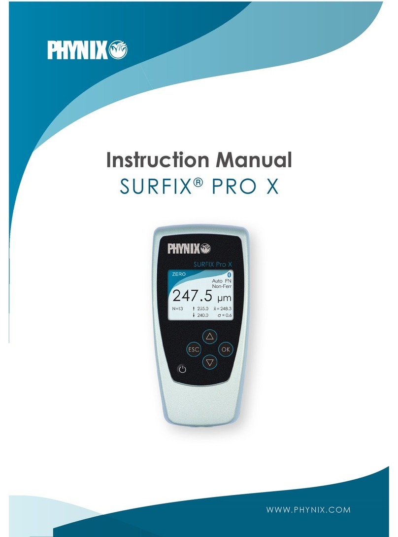
Instruction Manual
POCKET-SURFIX®
WWW.PHYNIX.COM

2

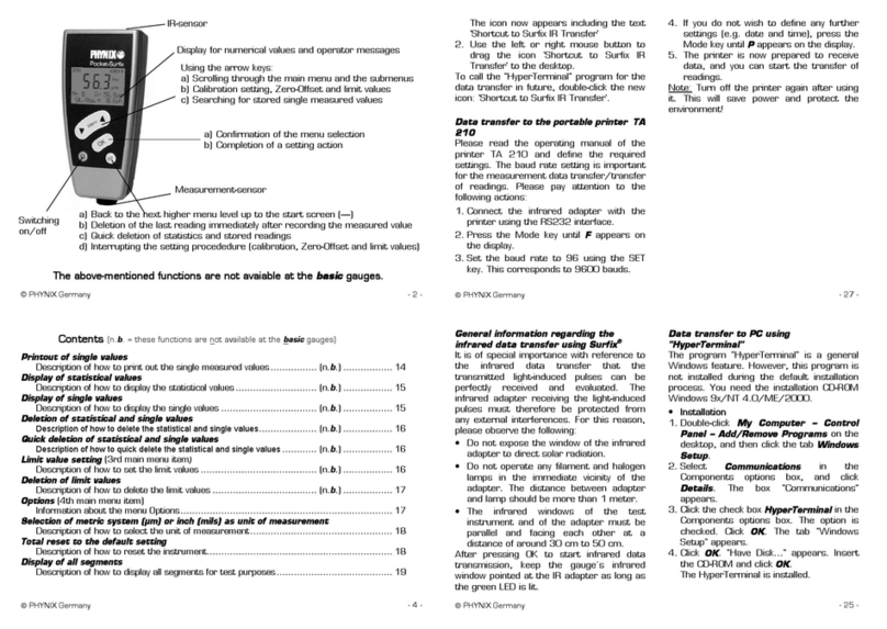
Gauge description
IR interface
Cursor-up-key
Confirm key
Cursor-down-key
Ansch luss
Power key
Escape key

2
Contents
About this manual 4
Meaning of keys 4
1. Gauge types and their applications 5
2. Preparing for measurement 7
3. Menu structure 7
4. Calibration (1st menu item) 8
4.1. Activating the works calibration 8
4.2. Zero setting (1-point calibration) 9
4.3. Foil calibration (2-point calibration) 9
4.4. Zero offset mode 10
4.4.1. Setting the zero offset value 11
4.4.2. Deleting the zero offset value 12
4.5. Deletion of calibration 12
4.6. Measurement 13
5. Statistics (2nd menu item) 14
5.1. Transfer of statistic values only 14
5.2. Transfer of readings and statistics 15
5.3. Display of statistics on the screen 16
5.4. Display of stored readings on the screen 16
5.5. Deletion of readings and statistics 17
5.6. Quick deletion of readings and statistics 17

3
6. Limits (3rd menu item) 18
6.1. Setting of limit values 18
6.2. Deletion of limit values 19
7. Options (4th menu item) 19
7.1. Measuring unit µm/mils 20
7.2. Setting of measuring mode: Automatic FN identification,
Ferrous mode and Non-Ferrous mode 20
7.3. Selection of switch-off modes 21
7.4. Backlight 22
7.5. Beeper on/off 22
7.6. Statistics settings 23
7.7. Welcome screen on/off 23
7.8. Power supply 24
7.9. Selecting the language 25
8. Total-Reset to factory settings 25
9. Display of firmware version number and serial numbers of gauge and probe 26
10. Status information, error messages und malfunctions 26
11. Maintenance / Service 28
12. Technical Data 28
13. Scope of delivery 29
14. Display 30
15. Default settings 31
16. Protect the environment 31

4
Introduction
The following operating manual is intended for coating thickness gauges of the Pocket-Surfix®series (with integrated
probe). The gauge conforms to the following standards for coating thickness measurement:
Magnetic method: DIN EN ISO 2808
DIN EN ISO 2178
ASTM B499
ISO 19840
Eddy current method: DIN EN ISO 2808
DIN EN ISO 2360
ASTM D7091
About this manual
The well-proven menu technique is applied to the use of this coating thickness gauge. This manual informs you step by
step about the correct operation of the gauge Pocket-Surfix®. If you follow these step-by-step instructions, it will only
take a few minutes before you are able to carry out the first measurements.
Meaning of keys
The operation of Pocket-Surfix®is carried out by means of the five buttons below the display.
Switching the gauge on and off.
The arrow keys (actually , for better distinguishing and ) have several functions.
Depending on the menu item you are currently at, by using these keys you will:
browse through the main menu and submenus

5
set calibration values, limit values and zero offset value
browse through stored single readings.
Use this key to:
confirm the choice of a menu item, e.g. Statistics 2/4 and then reach the corresponding
submenu, e.g. Print out of statistics 1/6
close a setting action, e.g. µm unit, or confirm the calibration or limit value settings.
This key enables you to:
go back to the next higher menu level up to the start screen ––––
delete the last reading immediately after the measurement
delete readings and statistics quickly (see chapter 5.6)
abort a setting action, e.g. when setting calibration and limit values.
1. Gauge types and their applications
Depending on the delivery, you either have the standard instrument Pocket-Surfix®or the Pocket-Surfix®basic with
limited functionality.
The Pocket-Surfix®gauge has all the functions described in this manual. The Pocket-Surfix®basic gauge has a limited
number of functions; all statistics, limits, the zero offset and the backlight are missing.
Pocket-Surfix®is a coating thickness gauge for non-destructive coating thickness measurement according to the
magnetic induction principle and the eddy current principle.
The magnetic induction principle is used for all non-magnetic coatings, such as varnish, paint, enamel,
chromium, copper, zinc... coatings on steel and iron (F types)
The eddy current principle is used for all electrically insulating coatings, such as varnish, paint and anodising
coatings on non-ferrous metals, even on austenitic stainless steels (N types).
FN types are dual gauges for measurements on steel and non-ferrous metal (F = Ferrous und N = Non-Ferrous).

6
The following gauges are available:
Model
Application
Range
Accuracy
(referred to PHYNIX standards)
1works calibration
21-point calibration
32-point calibration
Pocket-Surfix®FN
dual gauge for measurements on
steel/iron and on non-ferrous metals
0 … 1500 µm
13 µm or 3 % of reading;
whichever is greater
2(1 µm + 2 % of reading)
3(1 µm + 1 % of reading)
Pocket-Surfix®F
for measurements on steel/iron
Pocket-Surfix®N
for measurements on non-ferrous
metals
Pocket-Surfix®FN basic
dual gauge for measurements on
steel/iron and on non-ferrous metals;
reduced functionality
Pocket-Surfix®F basic
for measurements on steel/iron;
reduced functionality
Pocket-Surfix®N basic
for measurements on non-ferrous
metals;
reduced functionality

7
2. Preparing for measurement
Power supply:
Pocket-Surfix®can be operated using 2 x round cell (AAA) 1.5V alkaline batteries or also 2 rechargeable batteries
(AAA) 1.2V. Please pay attention to chapter 7.8 “power supply”.
Empty batteries are indicated by a flashing battery icon. Please remove used batteries at once and dispose them in
an environmentally acceptable manner.
When inserting new batteries, please pay attention to the correct polarity. Wrongly inserted batteries may lead to a
destruction of the gauge.
In order to avoid any possible loss of data, please pay attention when exchanging batteries:
a) Always switch off the gauge by means of the button before exchanging batteries.
b) Exchange the batteries within 20 seconds.
After inserting the batteries and switching-on for the first time by means of the button, the display may show English
as proposed language: confirm with , or use the arrow keys to select another language and confirm with .
Normally the gauge works in the automatic switch-off mode. It switches off the gauge automatically 90 seconds after
the last measurement or operation. For permanent opertion mode see chapter 7.3.
3. Menu structure
There are 4 main menu items: Calibration, Statistics, Limits and Options. All other menu items or functions are
subordinate to these 4 menu items.
The operation is carried out by means of the two arrow keys and , the confirmation key and the escape key .
The steps to be carried out are displayed on the screen, e.g. “Place probe on foil standard“. After pressing the
confirmation is displayed, e.g. „Calibration has been set“.
You can find a diagram of the menu structure at the end of this manual. A single look at this structure is sufficient to
recognize the applicable menu items to select a desired function.

8
4. Calibration (1st menu item)
This section informs you about the different calibration modes and the application cases that they are especially
suitable for. To meet the demands of coating thickness measurement tasks the accuracy of the gauge has to be
checked regularly by means of the calibration standards included in the scope of delivery.
With Pocket-Surfix®you can directly measure without any further user interaction. Readings, calibration values and
settings are stored consecutively in the memory, in case of Pocket-Surfix®FN either in the F memory or in the N memory.
The differentiation between F memory and N memory means also that e.g. setting of limit values has to be done in
both measuring modes, if desired. This working principle of Pocket-Surfix®enables very quick measurements; all
readings are within one single memory (FN type: two single memories).
Pocket-Surfix®is works calibrated. If the accuracy of the works calibration is not sufficient or if the measurement task
makes it necessary you can do some additional calibrations as described below.
A zero calibration on an uncoated specimem reduces measurement errors induced by surface geometry e.g. by
curved surface or near edges. Calibration data is preserved during power off. Pocket-Surfix®uses three different
calibration methods (see Technical Data chapter 12).
4.1. Activating the works calibration
This calibration mode is suitable for measurements on flat surfaces larger than 35 mm x 35 mm / 1.4” x 1.4”. A
calibration that has been carried out previously has to be deleted. You need neither calibration standards nor any
uncoated test objects.
Procedure:
1.
press this key; Calibration appears on the display.
2.
press this key; Zero setting appears on the display.
3.
press this key; Deletion of calibration appears on the display.

9
4.
press this key; Works calibration activated appears on the display followed by the
start screen with the four dashes ––––.
You can now measure using the works calibration.
4.2. Zero setting (1-point calibration)
For this purpose, you have to use an uncoated test object having similar dimensions and material properties as the
coated test object, e.g. when you plan to measure on small cylindrical parts or near edges. The zero plates delivered
with your gauge are not intended to be used for zero calibration; instead use these plates together with the calibration
foils to check the accuracy of the gauge.
Procedure:
1.
press this key; Calibration appears on the display.
2.
press this key; Zero setting appears on the display.
3.
press this key; Place probe on “0” appears on the display, and the ZERO symbol in the
display begins to flash.
4.
place the gauge repeatedly on the uncoated surface of the test object.
5.
press this key. Zero has been set appears briefly on the display followed by the start
screen with the four dashes ––––. The ZERO symbol is visable permanently.
You can now measure using the 1-point calibration.
4.3. Foil calibration (2-point calibration)
The foil-calibration has to be done on an uncoated test object (as with the zero setting). For the foil-calibration choose
a calibration foil that comes closest to the expected coating thickness.

10
Procedure:
1.
Carry out ‚zeroing’ (1-point calibration) as described above (please see chapter 4.2).
2.
press this key; Calibration appears on the display.
3.
press this key; Zero setting appears on the screen.
4.
press this key one more time; Foil calibration appears on the screen.
5.
press this key; Place probe on foil standard appears on the display and the CAL
symbol in the display begins to flash.
6.
Put the calibration foil on the uncoated test object and place the probe repeatedly
on the foil.
7.
press this key; set standard value appears on the display.
8.
use the arrow keys to enter the calibration foil thickness as indicated on the standard.
9.
press this key; Calibration has been set appears briefly on the display followed by the
start screen with the four dashes ––––. The CAL symbol is visable permanently.
You can now measure using the foil calibration.
4.4. Zero offset mode
With this mode you can set a constant positive or negative value (zero offset value). This value will be added
automatically to the reading after each measurement. The sum of original reading and zero offset value is then shown
on the display. Moreover, the zero offset value is always displayed at the bottom of the display as a reminder (e.g.
Offset=10.0µm).

11
This measuring mode is useful when it comes to determining the upper layer in a coating system consisting of several
layers. If the lower layer(s) is (are) known and show(s) an adequately uniform thickness, the coating thickness of this
(these) layer(s) can be set as a negative offset value. After measuring of the total coating thickness the thickness of
the lower layer(s) is subtracted (addition of a negative offset value) and the thickness of the top layer is displayed.
This mode can also be selected for measurements on coated rough metal surfaces. The influence of the roughness is
determined by measuring the uncoated rough metal surface and set as a negative zero offset value. The gauge will
then indicate the coating thickness above the peaks of the rough surface.
4.4.1. Setting the zero offset value
Procedure:
1.
press this key; Calibration appears on the display.
2.
press this key; Zero setting appears on the display.
3.
press this key twice until Zero offset appears on the display.
4.
press this key; Offset setting appears on the display.
5.
press this key; Set offset value appears on the display.
6.
use these keys to adjust the zero offset value; with continued pressing of these keys the set
value increases or decreases faster.
7.
press this key; Offset has been set appears briefly on the display followed by the start
screen with the four dashes ––––. As indicator the zero offset value can be seen at the
bottom of the display (e.g. Offset=10.0 µm).
After this all readings will be corrected by the zero offset value.

12
Example: with a real coating thickness of 100 µm and a zero offset value of –10 µm the display shows 90 µm. With a real
coating thickness of 100 µm and a zero offset value of +10 µm the display will show 110 µm. The corrected value (90 µm
resp. 110 µm) is stored in the memory.
The zero offset value is only set for the measuring method (Ferr, Non-Ferr) which was activated last. When the base
material changes the zero offset value has to be set again, if desired.
4.4.2. Deleting the zero offset value
Procedure:
1.
press this key; Calibration appears on the display.
2.
press this key; Zero setting appears on the display.
3.
press this key twice until Zero offset appears on the display.
4.
press this key; Offset setting appears on the display.
5.
press this key; Deletion of offset appears on the display.
6.
press this key; Offset deleted appears briefly on the display followed by the start screen with
the four dashes ––––. The zero offset value indicator disappears.
4.5. Deletion of calibration
This menu item allows you to delete the active calibration. However, if you would like to overwrite a calibration, a
deletion is not necessary beforehand.

13
Procedure:
1.
press this key; Calibration appears on the screen display.
2.
press this key; Zero setting appears on the screen.
3.
press this key once; Deletion of calibration appears on the screen display.
4.
press this key; Works calibration activated appears briefly on the display followed by the
start screen with the four dashes ––––.
You can now measure using the works calibration.
4.6. Measurement
This section describes the suitable application cases of the different gauge types. You can use F types for
measurements on all non-magnetic coatings, e.g. varnish, paint, plastics, chrome, zinc, etc. coatings on iron/steel. The
display shows Ferr. You can use N types for measurements on all electrically insulating coatings, e.g. varnish, paint,
plastics, anodized coatings, etc. on non-ferrous metals. The display shows Non-Ferr.
The FN combination gauges allow both measurements and is factory-set to the measuring mode Auto FN
identification. The display shows AUTO FN. This means that the gauge automatically identifies the base material
(iron/steel or non-ferrous metal) after positioning of the probe. Subsequently the gauge switches to the corresponding
measuring method, magnetic (F) or eddy current method (N). After each measurement the display shows Ferr or Non-
Ferr to indicate the base material.
Note: In some cases, especially with varnish on zinc on steel, it is nevertheless recommended to switch off Auto FN
identification and to use a fixed measuring method setting, e.g. Ferrous mode (F) for measurements on iron/steel or to
Non-Ferrous mode (N) for measurements on non-ferrous metals. See chapter 7.2 for details.

14
5. Statistics (2nd menu item)
After each measurement Pocket-Surfix® stores the readings in a data memory and calculates a variety of statistic
parameters. Pocket-Surfix® stores up 80 readings in its data memory.
The statistical values are updated after each measurement and stored together with the thickness values. The display
shows the number of measurements N, the mean value x¯ , the standard deviation s, the maximum value Max of the
series and the minimum value Min .
Parameter
Statistics
N
Number of readings
x¯
Mean value
St.Dev.
Standard deviation
Max
Maximum value of the series
Min
Minimum value of the series
All readings and statistics can be completely transferred or displayed at the menu item Statistics.
5.1. Transfer of statistic values only
The gauge calculates five statistical values from a measurement series (see table above). These can be quickly and
simply transferred to a PC in the 2nd menu item Statistics.
Transfer can be made immediately after the measurement. Data transfer to a PC can be done by means of the infra-
red interface at the top of the gauge. Use PHYNIX infra-red adapter (art.no. 10641) for the connection. The data

15
transfer program PHYNIX.connect receives the data and shows it on the screen. PHYNIX.connect is ready for
download at www.phynix.com.
Procedure:
1.
Connect the PC with the PHYNIX infra-red adapter (art.no. 10641). Run PHYNIX.connect on
your PC. Select the appropriate port. For details see instruction manual of the software.
2.
press this key twice until Statistics appears on the display.
3.
press this key; Printout of statistics appears on the display. Direct the top of gauge towards
the IR adapter.
4.
press this key. Data is transferred and Printing... appears briefly on the display, followed by
the start screen with the four dashes ––––.
5.2. Transfer of readings and statistics
The statistical values can also be transferred together with the single readings.
Procedure:
1.
Connect the PC with the PHYNIX infra-red adapter (art.no. 10641). Run PHYNIX.connect on
your PC. Select the appropriate port. For details see instruction manual of the software.
2.
press this key twice until Statistics appears on the display.
drücken; es erscheint Kalibrierung
3.
press this key; Printout of statistics appears on the display.
drücken; es erscheint Null-Einstellung
4.
press this key; Printout of measurements appears on the display. Direct the top of gauge
towards the IR adapter.
sooft drücken bis Löschen der Kalibrierung erscheint
5.
press this key. Data is transferred and Printing... appears briefly on the display, followed by
the start screen with the four dashes ––––.

16
5.3. Display of statistics on the screen
This section explains how to show the different statistical values on the display.
Procedure:
1.
press this key twice until Statistics appears on the display.
2.
press this key; Printout of statistics appears on the display.
3.
press this key twice until Display of statistics appears on the display.
4.
press this key. Number of readings N, the mean value x¯ and the standard deviation St.Dev.
appears on the display.
5.
press this key. Number of readings N, the maximum Max and the minimum Min appears on
the display.
6.
press this key three times to continue measuring. The start screen with the four dashes ––––
is displayed.
5.4. Display of stored readings on the screen
This section explains how to display the readings on the screen at any time.
Procedure:
1.
press this key twice until Statistics appears on the display.
2.
press this key; Printout of statistics appears on the display.
3.
press this key three times until Display of measurements appears on the display.

17
4.
press this key; the first single value appears on the display.
5.
press this key repeatedly. The following single values with a consecutive number are
displayed. Symbols (▼,▲) indicate a reading out of the limits.
6.
press this key three times to continue measuring. The start screen with the four dashes ––––
is displayed.
5.5. Deletion of readings and statistics
This section explains how to delete the readings in the data memory.
Procedure:
1.
press this key twice until Statistics appears on the display.
2.
press this key; Printout of statistics appears on the display.
3.
press this key until Deletion of statistics appears on the display.
4.
press this key. The statistics are deleted together with the single values. Statistics deleted
appears briefly on the display followed by the start screen with the four dashes ––––.
5.6. Quick deletion of readings and statistics
This procedure offers a simple and fast way to delete all readings and statistical values by circumventing the menu
structure.
Procedure:
1.
press this key repeatedly until the start screen with the four dashes
––––appears on the display.
2.
press this key once more; Delete statistics? appears on the display.

18
3.
press this key; Statistics deleted appears briefly on the display followed by the start screen
with the four dashes ––––.
6. Limits (3rd menu item)
This section describes the setting of limit values. To monitor your readings, you can set an upper and a lower limit value.
This setting is useful:
during the measurement
for the evaluation of readings later on when displaying the single values
during the analysis of the readings with the PC.
If the reading is outside of the limit values, you will hear a characteristical beep, and an indicator ▼or ▲at the top of
the display shows whether the reading fell below or exceeded the limit values.
6.1. Setting of limit values
Procedure:
1.
press this key three times until Limits appears on the display.
4.
press this key; Limits setting appears on the display.
5.
press this key; Set lower limit appears on the display and a number as suggestion for the
lower limit value.
6.
use these keys to adjust the lower limit value; with continued pressing of these keys the set
value increases or decreases faster.
7.
press this key; Set upper limit appears on the display and a number as suggestion for the
upper limit value; the upper limit value must be at least 10 µm higher than the lower limit
value.
This manual suits for next models
6
Table of contents
Other Phynix Measuring Instrument manuals
Popular Measuring Instrument manuals by other brands

Endress+Hauser
Endress+Hauser Liquiphant S FDL60 Functional safety manual

Flomec
Flomec QS100-10 Product owners manual

Berkeley Varitronics Systems
Berkeley Varitronics Systems WallHound-Pro user manual

NKE
NKE SAMBAT user manual

Sierra
Sierra MaxTrak 180 Series instruction manual

Endress+Hauser
Endress+Hauser Proline t-mass 65 operating instructions

PCE Instruments
PCE Instruments PCE-USC 20 operating manual

Laserworld
Laserworld MK3 Series manual

Fluke
Fluke CableAnalyzer DSP-4000 Series user manual

Extech Instruments
Extech Instruments 407750 user guide

Johnson Level & Tool
Johnson Level & Tool LDM330 instruction manual

KLINGER
KLINGER PS116 Operation manual