Piaa 1100p Series User manual

-1-
PKI-0052
1100p Series
Installation Instructions
Thank you very much for purchasing PIAA product.
Please read this entire manual before installation and use of this product.
Please read the cautionary points before installation to ensure safe utilization of the product.
※ The and marks indicated in this manual are
cautionary points related to the installation of the product.
To ensure safe and secure installation of the product, please follow these points closely.
To user … Please keep this manual and a receipt with the name of the shop
where you bought it.
When giving this product to a third party, always include this manual
together with the product.
To shop owners installing the product … After installation of the product, make sure the customer is provided
with this owner’s manual.
● The lamp and the switch harness are intended for automotive and powersports vehicle use only.
Do not use for any other purpose.
● This lamp is intended for use in rain (day or night), during foggy or snowy conditions where visibility is hampered.
Irresponsible use of any auxiliary light can be dangerous and illegal. Check your local lighting laws, as they can vary from state
to state.
● Do not operate the switch while driving.
● If the lamp is kept on when the engine is not running, it may drain the battery.
● Make sure the lamp is installed securely before driving the vehicle. If a problem is found, x it immediately.
● Check for any loose screws that hold the lamp in place before driving. If you nd any loose screws or bolts (if a bracket is
used), tighten them securely. If you notice a loose part while driving, inspect the section immediately and make the necessary
adjustments.
● Avoid repeatedly turning the lamp o and on as it may reduce the overall life of the LED.
● Some vehicles produce a high voltage electric charge when the engine is started. Avoid loading extra voltage to lamps by
turning the switch o when you start engine.
● Avoid needless disassembly of the lamp or the switch harness as it may cause it to fail.
● If the lamp and/or the switch harness is removed and set aside for safekeeping, wipe away all dust or grime and store in a
place free of moisture.
● If the lens is cracked or damaged in any way, verify whether there is any damage to the harness. If there is any damage to
the cord covering, replace it immediately.
● Avoid injury when replacing the harness and the switch harness. Please dispose of it as a non-combustible item.
● The lamp becomes very hot when turned on. When parking your car near ammable items such as dried leaves, turn o the
lamp as it may cause a re.
● Do not look directly into the light for long periods. Doing so may cause eye irritation or visual impairment.

-2-
PKI-0052
Please read the installation procedures thoroughly beforehand.
Caution Regarding Wiring / Please read thoroughly
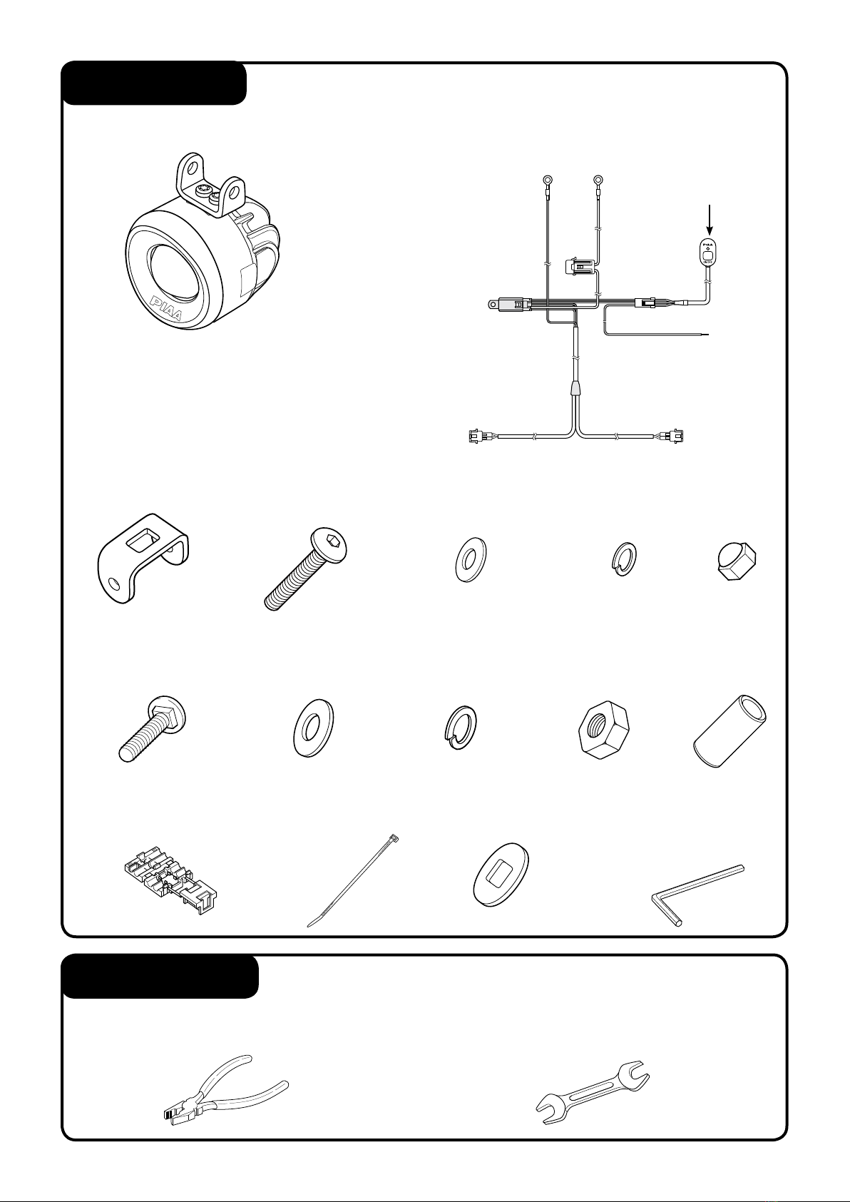
● In order for the lamp to perform at its full potential, use the relay harnesses manufactured by PIAA.
● All work procedures should be carried out in a location with adequate space. Place the shift lever in neutral or in the parking
position. Turn o the engine and set the parking brake.
● Make sure the engine compartment is adequately cool before starting work. Do not begin work if engine parts such as radiator,
oil-cooler or turbo parts are still hot.
● Do not add additional holes to the main body of the lamp. Also, do not apply adhesives or stickers to the lamp parts.
● Do not modify the lamp harness or the switch harness in any way. Such modications may cause it to overheat or short. In some
cases, it may cause the vehicle to catch re. PIAA will not be liable for damage caused by such modications.
● When removing the battery terminals, do not touch the (-) and (+) terminals simultaneously. An electrical shock may occur.
Wear rubber gloves when carrying out such work procedures.
● Make sure the (-) and (+) terminals do not make contact with metal. It can be extremely dangerous if a short occurs.
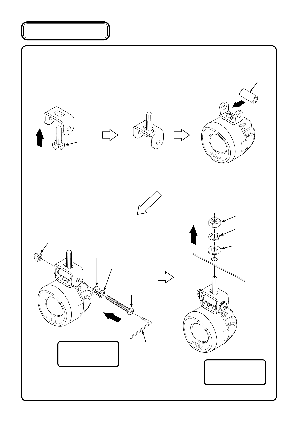
● Make sure all bolts are tightly secure. If there are any loose bolts tighten them accordingly.
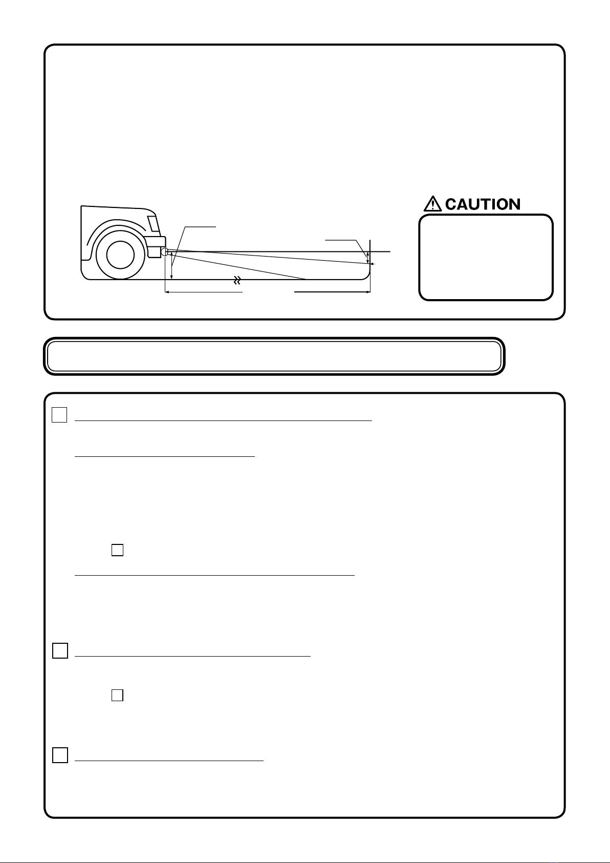
● After installing the lamp, adjust the lamp so the beam shines at least 40m in front of the vehicle. Also, adjust the lamp a little
toward the right so that it does not shine directly into the eyes of the opposing driver of a vehicle. (as trac laws stipulate -
refer to p.7 for adjustment procedures)
● After installing the lamp, make sure the headlamps, wipers and horn are working normally.
● When the battery terminal is removed, memory related to the clock, radio, audio system etc, will be aected. After all work
procedures are completed, reset to the original settings. (For adjustment procedures refer to your car’s instruction manual)
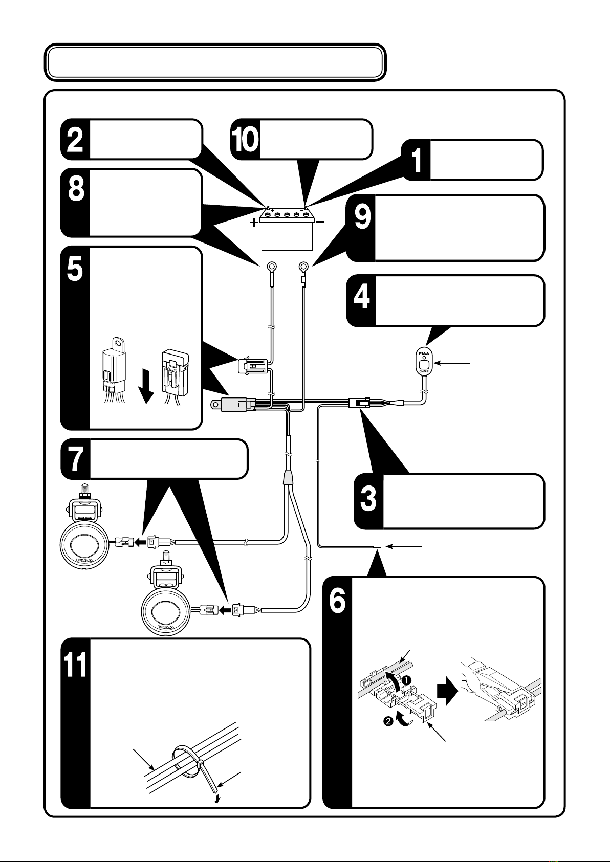
● Before you begin always remove the (-) and (+) terminals.
Always remove the (-) terminal rst and make sure a short does not occur.
● When removing the battery terminals, always turn the key to OFF and remove it. Turn all other electrical units o such as
the light switch.
● When removing the battery terminals, if a cord (for an electrical unit) is connected, wind a length of vinyl tape around the
(-) and (+) terminals to clearly identify them.
● Verify the (+) terminal (white) and earth (black) before connecting.
● Do not obtain (+) voltage from the alternator.
● Obtain the (+) current necessary for the switch from the (+) current used for the light switch.
(Do not use the same current used for a computer, radio or audio system)
● Install the switch harness in a position where it will not make contact with high temperature surfaces such as the engine,
radiator or engine compartment.
● Arrange the switch harness so that it does not make contact with moving parts.
● Do not place the switch harness on high-voltage wires such as brake or air-conditioning wires.
● If the switch harness makes contact with a part of the engine, apply a length of ordinary cushioned tape around the harness.
● When connecting the connector, insert until you hear an audible “click”
● When removing the connector, hold the main body of the connector and pull it out. If excess force is used to pull the cord, it
may damage the connection, which could cause it to overheat.
● Make sure the harness does not sag. Use a harness band of vinyl tape to secure it in place to wiring inside the engine compartment.
● Before connecting it to the battery, verify the wiring arrangement.
● When connecting the battery terminal and or other electrical units, do not mistake the (-) and (+) terminals. Always start with
the (+) terminal.
● After all wiring is complete, conrm that it works properly. If it fails to activate, refer to“【3】Troubleshooting”section
of this manual.
● When installing the wiring harness, strictly follow the cautionary points mentioned below. Incorrect or faulty wiring may cause
the lamp to operate improperly. In some cases, it may cause the vehicle to catch re.

-3-
PKI-0052
※ Verify all the parts are included. If a part is missing, please contact your local distributor.
Product Details
switch
① Lamp main unit (2 units) ② Pre-assembled relay harness
with fuse and switch (1 set)
⑨ Flat washer
:Large (2 pc)
⑬ One-touch connector
(1 pc)
④ Hexagon socket head bolt
(2 pc)
⑭ Wire tie
(5 pcs)
⑤ Flat washer
:small (2 pc)
⑦ Cap Nut
(2 pc)
⑫ Collar
(2 pc)
⑯ Hexagonal wrench
(1 pc)
③ Bracket
(2 pc)
⑧ Carriage bolt
(2 pc)
⑪ Nut
(2 pc)
⑮ Double-stick tape
(1 pc)
⑥ Spring washer
: small (2 pc)
⑩ Spring washer
: Large (2 pc)
This Package encloses either LED Fog Lamp.
※ Please use the tools indicated below.
● Pliers
Tools Required
● 10mm wrench / 13mm wrench

-4-
PKI-0052
For lamp installation, a hole with a diameter of 8mm is required. Make necessary preparation
such as installation of lamp bracket.
【1】Lamp installation
Tightening torque:
3.8ft・lbs (5.2N・m)
Tightening torque:
9.5ft・lbs (13N・m)
● This Instruction Manual (IM) refers to the “LED Driving Lamp” system
but can also be applied to the “LED FOG Lamp” system.
①
③
④
③
②
Flat washer
:Large
Flat washer
:small
Carriage bolt
Hexagonal wrench
Cap Nut
Collar
Hexagon socket
head bolt
Spring washer
:Large
Spring washer
:small
Nut

-5-
PKI-0052
● The lamp should be tightened to the degree that the lamp body cannot be moved by hand.
● The lamps are designed to be hanging down. It is very important that you make sure that
the “PIAA” etched in the rim reads right side up.
Make sure the installation
position is correct and the
logo will not be upside down.
● When using a commercially supplied lamp bracket, before removing the bolt that is already
installed on the car body, make sure that it is safe to do so.
● The lamp should be mounted in an area sucient to support its size and weight. Failure to do
so may result in excess vibration leading to shorter bulb life and or physical damage to the
lamp or your vehicle.
● Do not attempt to install the lamp directly to any plastic part of the vehicle body.
If the lamp needs to be installed on the plastic
reinforcement materials should be placed on both sides of the plastic part.
● When installing, make sure the lamp body, lens and rim are not touching the bumper and
other plastic parts. Such plastic parts might deform.
● The lamp installation surface should be at.
● Do not use an Impact wrench when mounting the lamp.
● Over torquing the mounting nut on the base could cause
base failure and void the warranty.
● You must utilize the at washer and spring washer.
●Torque specications on the base mounting nut is 9.5ft・lbs (13N・m)
●Torque specications on the bracket mounting nut is 3.8ft・lbs (5.2N・m)
Impact wrench

-6-
PKI-0052
The numbers shown in the gure below indicate the sequence the parts should be installed.
Remove the (-) terminal
from the battery.
Remove the (+) terminal
from the battery.
Bring the relay connector into the
interior of the vehicle and connect
to the switch’s connector.
Take the (+) cord (white) and using the
one-touch connector, tie it together to the
vehicle’s (+) cord.
Connect the lamp harness to the
connector.
First ground the terminal then take the (-)
cord (black) and connect it
to the (-) terminal.
Take the (+) terminal
cord (white) and attach
it to the (+) terminal and
connect to the battery.
Attach the (-) terminal to
the battery.
After lamp has been installed, verify the relay
harness does not make contact with the
engine’s moving parts or sections that emit
extreme heat. Use the wire tie included and
secure to harnesses inside engine compartment.
【2】Relay Harness Installation Sequence
Harness
Wire tie
※ Use a pair of pliers to verify the
one-touch connector is secure.
Switch
Relay
Battery
Cord
One-touch connector
(+) cord (white)
(-) cord (Black)
Make sure to properly
secure the relay unit
using bolts or a harness.
The harness must also
be facing downward.
Double-stick tape for switch. Place
in area that is easily accessible from
driver’s seat.
Facing down
(+)cord

-7-
PKI-0052
1 After installation, if the lamp does not activate
→ Check the wiring and make sure there are no faulty or irregular connections.
● If the switch illumination does not light up.
→ Verify the (+) wire from the switch is properly connected. If it is not correctly connected it will not activate.
→ Verify the fuse located on the vehicle’s wiring system. (the switch’s (+) wire should be connected to the
fuse box). If it is burned out, connect it to another circuit.
→ If the switch itself is faulty, the same symptoms may exist. We recommend that the entire switch unit
be replaced.
→ Check the fuse for the switch harness. If it is burned out, follow instructions indicated in
[ 3 Fuse replacement Procedures].
● The switch illumination lights up but when operating does not work.
→ Check the connecting (-) cord to the body earth.
→ There may be cases where each terminal related to specic sections may be incorrectly connected.
Check for any lose wires and also for dirt or grime.
→ Check the switch operation If an abnormality is found, replace it accordingly.
2 If the LED suddenly fails to light up …
→ Check the fuse located on the vehicle’s wiring system. If it is burned out, replace accordingly.
→ Check the fuse for the switch harness. If it is burned out, follow instructions indicated in
[ 3 Fuse replacement Procedures].
→ There may be cases where each terminal related to specic sections may be incorrectly connected.
Check for any lose wires and also for dirt or grime.
→ Check the switch operation if an abnormality is found, replace it accordingly.
3 Fuse replacement procedures
→ A short circuit may have occurred. Check the wiring system. If any type of damage is
found replace accordingly. (Non-replacement may pose a potential danger) (Short circuits are mainly
caused when wires are caught in the assembly or when there is a gap in the sleeve connected to the lamp harness).
【3】Troubleshooting……
Verify each section according to the following.
There are two important issues to address when installing fog lights, the rst is to minimize the amount of return glare into
the drivers eyes, and the other is to minimize glare into oncoming eyes. Both of those issues must be accomplished while
putting as much light as possible on the road.
These fog/foul weather light aiming instructions are suggestions taken from common
practice and the S.A.E. standard J583. Some modications to these instructions may
be necessary to minimize glare.
Visual aim is made with the top of the beam 4 inches below the lamp center at 25
feet with the lamp facing straight forward. (See below.)
● Only use fog lights if they
are aimed properly.
Fog lights should never be the
only foreword light source.
Fog lights should be used with
headlamp low beams.
FOG Light Aiming
25 feet
Measure lamp height to center.
Level
Top of
Beam
Four(4)inches

-8-
PKI-0052
【4】PIAA LIMITED WARRANTY
With the exception of bulbs, PIAA Corporation, USA ("PIAA") warrants its products to be free from
defects in workmanship and materials under normal use for as long as the original purchaser owns them.
EXCLUSIONS
This Limited Warranty specically excludes defects resulting from misuse, abuse, neglect, alteration,
modication, improper installation, unauthorized repairs, submersion, theft, vehicle crash, or by any
other type of impact. Except for the Limited Warranty stated above, there are no warranties of PIAA
products or any part thereof, whether express or implied. Any implied warranty of merchantability
or any warranty of tness for a particular purpose is expressly disclaimed. Some states do not
permit the disclaimer of implied warranties.
LENS CRACKS
Crash or impact damage is not covered. This can be determined by a chip or scrape on the lens or the
housing. Stress cracks sometimes occur when the lens is subjected to sudden and extreme temperature
changes. A stress crack has no chip or other sign of impact. Stress cracks are covered under warranty.
EXCLUSION OF DAMAGES
In no event shall PIAA be liable for any damages whatsoever (including, without limitation, consequential
damages, incidental damages, or damages for loss of use, loss of business prots, business interruption,
loss of business information, loss of time, inconvenience, or other losses) arising out of the use, misuse,
or inability to use a PIAA product. PIAA reserves the right to change the design its products without any
obligation to modify any previous product. This warranty gives you specic legal rights. You may also
have other rights that vary from state to state.
REPAIR AND REPLACEMENT
If a PIAA product is suspected of being defective, it must be submitted freight prepaid, to either an
authorized dealer or distributor for warranty inspection. The receipt or other proof of purchase and a
description of the problem must be included. The returned product will be inspected. If the product is
found to be defective and covered by this Limited Warranty, the sole remedy is repair or replacement, at
PIAA's option. A repaired or replacement product will be shipped back at no charge, and will be warranted
to be free from defects in workmanship and materials under normal use for as long as the original
purchaser owns it. Removal, installation, or reinstallation costs are not covered by this Limited Warranty.
PIAA CORPORATION
www.piaa.com
www.piaa.co.jp

-9-
PKI-0052
Serie 1100p
Instrucciones para la instalación
Muchas gracias por comprar un producto PIAA.
Lea este manual completo antes de instalar y usar este producto.
● La lámpara y el arnés del interruptor son solamente para usos automotores y para vehículos deportivos motorizados.
No la utilice para ningún otro propósito.
● Esta lámpara es para usarse bajo la lluvia (de día o de noche), en condiciones de niebla o nieve donde hay poca visibilidad.
No la use en condiciones normales de conducción.
● No accione el interruptor mientras conduce.
● Si la lámpara se queda encendida sin que el motor funcione, la batería puede descargarse.
● Antes de conducir el vehículo, asegúrese de que la lámpara está rmemente instalada. Si hay algún problema, repárelo de
inmediato.
● Antes de conducir, revise que ninguno de los tornillos que sujetan la lámpara esté ojo. Si encuentra ojo algún tornillo o perno
(si se usa un soporte), apriételo rmemente. Si nota alguna parte oja mientras conduce, revise la sección inmediatamente y
haga todos los ajustes necesarios.
● No encienda y apague repetidamente la lámpara pues eso puede reducir la vida útil del LED.
● Algunos vehículos producen una carga eléctrica de alto voltaje cuando se enciende el motor. Evite sobrecargar de voltaje las
lámparas apagando el interruptor al poner en marcha el motor.
● Evite desarmar innecesariamentela lámpara o el arnés del interruptor pues eso puede ocasionar fallas.
● Si se quita la lámpara y/o el arnés del interruptor y se aparta para su protección, limpie toda la suciedad y el polvo y guárdelo
en un lugar libre de humedad.
● Si la lente está rajada o sufre cualquier daño, verique si el arnés tiene algún daño. Si hay algún daño en el
forro del cable, sustitúyalo de inmediato.
● Evite lesiones al sustituir el arnés y el arnés del interruptor. Deseche la parte averiada como material no combustible.
● La lámpara se calienta mucho cuando está encendida. Cuando estacione su vehículo cerca de material inamable, como hojas
secas, apague la lámpara porque puede ocasionar un incendio.
● No mire directamente a la luz por largos períodos. Hacerlo puede ocasionar irritación de los ojos o discapacidad visual.
Lea las precauciones antes de la instalación para asegurarse de utilizar el producto con seguridad.
※ Las marcas y que se indican en este
manual son notas de precaución referentes a la instalación del producto.
Para asegurarse de que la instalación del producto sea segura y rme, siga elmente estos puntos.
Para el usuario … Conserve este manual y el recibo con el nombre de la tienda
donde lo compró.
Cuando entregue este producto a terceros, incluya siempre este manual
junto con el producto.
Para los dueños de tienda que instalan el producto … Después de instalar el producto, asegúrese de que el cliente reciba
su manual del propietario.

-10-
PKI-0052
● Para que la lámpara funcione con todo su potencial, use arneses de relevador fabricados por PIAA.
● Todos los procedimientos de trabajo deben realizarse donde haya el espacio adecuado. Coloque la palanca de cambios en
punto muerto o en posición de estacionamiento. Apague el motor y accione el freno de estacionamiento.
● Asegúrese de que el compartimiento del motor esté sucientemente frío antes de iniciar el trabajo. No inicie el trabajo si alguna
parte del motor, como el radiador, el enfriador de aceite o el turbo están calientes todavía.
● No haga oricios adicionales en el cuerpo principal de la lámpara. Tampoco aplique adhesivos o calcomanías en las partes de
la lámpara.
● No haga ninguna modicación en el arnés de la lámpara o en el arnés del interruptor. Esas modicaciones pueden causar
sobrecalentamiento o cortocircuito. En algunos casos, el vehículo puede incendiarse. PIAA no será responsable de daños
ocasionados por esas modicaciones.
● Al retirar los terminales de la batería, no toque al mismo tiempo los terminales ( − ) y (+). Puede recibir una descarga eléctrica.
Use guantes de caucho cuando realice esos procedimientos de trabajo.
● Asegúrese de que los terminales ( − ) y (+) no hagan contacto con el metal. Si se produce un cortocircuito, puede ser
extremadamente peligroso.
● Asegúrese de que todos los pernos estén bien apretados. Si hay pernos ojos, apriételos según se requiera.
● Después de instalar la lámpara, ajústela para que el haz de luz llegue al menos a 40 metros enfrente del vehículo.
Ajuste también un poco la lámpara hacia la derecha para que no apunte directamente a los ojos del conductor de un vehículo
que venga de frente. (Según lo establecen las leyes de tráco - vea los procedimientos de ajuste en la pág. 15)
● Después de instalar la lámpara, asegúrese de que los faros delanteros, los limpiaparabrisas y el claxon funcionen normalmente.
● Cuando se retira el terminal de la batería, las memorias del reloj, el radio, el sistema de audio, etc., resultan afectadas.
Después de completar los procedimientos de trabajo, restablezca los ajustes originales. (Para los procedimientos de ajuste, vea
el manual de instrucciones de su automóvil )
Lea con atención los procedimientos de instalación antes de proceder.
● Antes de empezar, retire siempre los terminales ( − ) y (+).
Retire siempre el terminal ( − ) primero y asegúrese de que no se produzca un cortocircuito.
● Al retirar los terminales de la batería, APAGUE siempre el motor y saque la llave. Apague todas las demás unidades eléctricas,
como el interruptor de luces.
● Si al retirar los terminales de la batería algún cable (de una unidad eléctrica) está conectado, enrolle un poco de cinta de vinilo
en los terminales ( − ) y (+) para identicarlos claramente.
● Compruebe cuáles son el terminal (+) (blanco) y el de tierra (negro) antes de conectarlos.
● No extraiga voltaje (+) del alternador.
● Extraiga la corriente (+) necesaria para el interruptor, de la corriente (+) que se usa para el interruptor de las luces.
(No use la misma corriente que utiliza para la computadora, el radio o el sistema de audio)
● Instale el arnés del interruptor en una posición en la que no toque supercies que estén a alta temperatura, como el motor,
el radiador o el compartimiento del motor.
● Acomode el arnés del interruptor de modo que no entre en contacto con partes móviles.
● No coloque el arnés del interruptor sobre cables de alto voltaje, como los del freno o el aire acondicionado.
● Si el arnés del interruptor toca alguna parte del motor, aplique un tramo de cinta de espuma ordinaria alrededor del arnés.
● Cuando conecte el conector, insértelo hasta que se produzca un “clic” audible.
● Al instalar el arnés de cables, siga estrictamente las precauciones que se mencionan abajo. El cableado incorrecto o
defectuoso puede hacer que la lámpara no funcione bien. En algunos casos, puede provocar que el vehículo se incendie.
Precaución sobre el cableado / lea con atención

-11-
PKI-0052
① Unidad principal de lámpara (2 unidades) ② Arnés de relevador pre-ensamblado
con fusible e interruptor(1 juego)
● Al retirar el conector, sostenga el cuerpo principal del mismo y tire de él para sacarlo. Si se utiliza demasiada fuerza al jalar el
cable, se puede dañar la conexión, lo cual puede provocar su sobrecalentamiento.
● Asegúrese de que el arnés no se combe. Use una banda de cinta de vinilo para asegurar el arnés en su lugar al cablear el interior del
compartimiento del motor.
● Antes de conectarlo a la batería, compruebe la disposición del cableado.
● Al conectar el terminal de la batería y/u otros dispositivos eléctricos, no confunda los terminales ( − ) y (+). Empiece siempre
con el terminal (+).
● Después de instalar todo el cableado, conrme que funcione bien. Si no se activa, consulte la sección “【3】Resolución de
Problemas” de este manual.
※ Compruebe que todas las partes estén incluidas. Si falta alguna, comuníquese con
su distribuidor local.
Detalles del producto
interruptor
Este Paquete contiene una Lámpara LED Antiniebla.
⑬ Conector de conexión
rápida (1 pza)
⑭ Cinta de amarre
(5 pzs)
⑯ Llave hexagonal
(1 pza)
⑮ Cinta adhesiva doble
(1 pza)
⑨ Arandela plana
:Grande (2 pzs)
④ Perno hexagonal
de cabeza hueca (2 pzs)
⑤ Arandela plana
:Pequeña (2 pzs)
⑦ Tuerca de
tapa (2 pzs)
⑫ Collar
(2 pzs)
③ Soporte
(2 pzs)
⑧ Perno de carro
(2 pzs)
⑪ Tuerca
(2 pzs)
⑥ Arandela de presión
: Pequeña (2 pzs)
⑩ Arandela de presión
: Grande (2 pzs)

-12-
PKI-0052
Para la instalación de la lámpara se requiere un agujero de 8mm de diámetro. Realice los preparativos
necesarios ,como la instalación de un soporte para lámpara.
【1】Instalación de la lámpara
Par de apriete:
9.5ft・lbs (13N・m)
Par de apriete:
3.8ft・lbs (5.2N・m)
● Este Manual de Instrucciones (IM) se reere al sistema “LED Driving
Lamp”(Faro LED de Largo Alcance), pero también puede aplicarse
al sistema “LED Fog Lamp” (Faro LED Antiniebla)
※ Use las herramientas que se indican abajo.
● Alicates
Herramientas necesarias
● Llave de 10mm / Llave de 13mm
④
③
Cap Nut
Hexagon socket
head bolt
Arandela plana
:Large
Arandela plana
:small
Tuerca
Arandela de presión
:Large
Arandela de presión
:small
①
③
②
Carriage bolt
Llave hexagonal
Collar

-13-
PKI-0052
Asegúrese que la instalación
esté en la posición correcta y
el logo no quede de cabeza.
● La lámpara debe apretarse hasta el punto en que no sea posible moverla manualmente.
● Las lámparas están diseñadas para montaje vertical. Es muy importante que se asegure de que el letrero
“PIAA” grabado en la lente se lea con el lado derecho arriba.
● Cuando use un soporte para lámpara de distribución comercial, antes de retirar el perno que ya está instalado
en la carrocería, asegúrese de que puede hacerlo con seguridad.
● La lámpara debe montarse en un área adecuada que soporte su tamaño y su peso. No hacerlo así puede
provocar una vibración excesiva que acorta la vida de la bombilla y/o un daño físico a la lámpara o a su vehículo.
● No intente instalar la lámpara directamente en ninguna parte de plástico de la carrocería del vehículo.
Si es necesario instalar la lámpara sobre el plástico, deberán colocarse materiales de refuerzo en ambos lados de
la parte de plástico.
● Al instalar, asegúrese de que el cuerpo, la lente y el marco de la lámpara no toquen el parachoques yotras partes
de plástico. Esas partes de plástico podrían deformarse.
● La supercie donde instale la lámpara debe ser plana.
● No use una pistola de impacto para montar la lámpara.
● Si aprieta demasiado la tuerca de montaje sobre la base, puede provocar daños
a la base y anular la garantía.
● Debe usar la arandela plana
y la arandela de presión.
● Las especicaciones de par de torsión sobre la tuerca de
la montura de la base son 9.5pies・lbs (13N・m)
● Las especicaciones de par de torsión sobre la tuerca de
la montura de la soporte son 3.8pies・lbs (5.2N・m)
Pistola de impacto

-14-
PKI-0052
Los números que aparecen en la gura de abajo indican el orden en que se deben instalar las partes.
【2】Secuencia de instalación del arnés del relevador
Desconecte el terminal
( − ) de la batería.
Desconecte el terminal
(+) de la batería.
Lleve el conector del relevador al
interior del vehículo y conéctelo
al conector del interruptor.
Tome el cable (+) (blanco) y usando el
conector de conexión rápida, únalo al
cable (+) del vehículo.
Conecte el arnés de la lámpara al
conector.
Primero conecte a tierra el terminal y
después tome el cable ( − ) (negro) y
conéctelo al terminal ( − ).
Tome el cable del terminal
(+) (blanco), y únalo al
terminal (+) y conéctelo a
la batería.
Conecte el terminal ( − )
a la batería.
Después de instalar la lámpara, verique que el arnés
para relevador no entre en contacto con las
partes móviles del motor ni con secciones que irradien
calor extremo. Use la amarra de alambre incluida y
asegúrela al arnés dentro del compartimiento del motor.
Arnés
Cinta de amarre
※ Con un par de alicates, compruebe que el
conector de conexión rápida esté rme.
Interruptor
Relevador
Batería
Cable
Conector de
conexión rápida
Cable (+) (blanco)
Cable (
−
) (negro)
Asegúrese de jar bien
la unidad del relevador,
usando pernos o un arnés.
El arnés debe estar
con el frente hacia abajo.
Cinta adhesiva doble para el interruptor.
Colóquelo en un área fácilmente accesible
desde el asiento del conductor.
El frente hacia abajo
Cable (+)

-15-
PKI-0052
Dos cosas importantes se deben de considerar al instalar luces anti niebla; la primera es minimizar la intensidad
del reejo que llega a los ojos de los conductores, y la otra es minimizar el deslumbramiento a quienes vienen de
frente. Esos dos objetivos deben lograrse, procurando proyectar la mayor cantidad de luz posible sobre el camino.
Estas instrucciones para dirigir la luz antiniebla o contra el mal tiempo son sugerencias tomadas de la práctica
ordinaria y de la norma S.A.E. J583. Puede ser necesario modicar estas instrucciones para minimizar el
deslumbramiento.
El objetivo visual se alcanza cuando la parte superior del haz está 4 pulgadas debajo del centro de la lámpara,
a 25 pies, con la lámpara apuntando hacia el frente. (Véase más abajo.)
● Use luces antiniebla solamente si están correctamente dirigidas.
Las luces antiniebla nunca deben ser la única fuente luminosa hacia el frente.
Las luces antiniebla deben usarse con la luz baja de los faros delanteros.
Dirección de LuzANTINIEBLA
25 pies
central.
Cuatro (4) pulgadas Nivel
Parte superior
del Haz

-16-
PKI-0052
1 Si la lámpara no se activa después de la instalación,
→ Revise el cableado y asegúrese de que no haya conexiones defectuosas o irregulares.
● Si la iluminación del interruptor no enciende.
→ Compruebe que el cable (+) del interruptor esté bien conectado. Si no está correctamente conectado, no
se activará.
→ Revise el fusible ubicado en el sistema de cableado del vehículo. (el cable (+) del interruptor debe estar
conectado a la caja de fusibles). Si está quemado, conecte el interruptor a otro circuito.
→ Si el interruptor está defectuoso, pueden presentarse los mismos síntomas. Entonces recomendamos que
toda la unidad del interruptor se sustituya.
→ Revise el fusible del arnés del interruptor. Si está quemado, siga las instrucciones que se indican en
[ 3 Procedimientos para Sustituir Fusibles].
● La iluminación del interruptor enciende, pero cuando está en operación no funciona.
→ Revise el cable (-) de conexión a la carrocería.
→ Puede haber casos en que cada terminal destinado a secciones especícas esté incorrectamente conectado.
Revise si hay cables ojos y también si hay polvo o suciedad.
→ Revise el funcionamiento del interruptor; si encuentra algo anormal, sustitúyalo según corresponda.
2 Si de pronto el LED no enciende …
→ Revise el fusible ubicado en el sistema de cableado del vehículo. Si está quemado, sustitúyalo según
corresponda.
→ Revise el fusible del arnés del interruptor. Si está quemado, siga las instrucciones que se indican en
[ 3 Procedimientos para Sustituir Fusibles].
→ Puede haber casos en que cada terminal destinado a secciones especícas esté incorrectamente conectado.
Revise si hay cables ojos y también si hay polvo o suciedad.
→ Revise el funcionamiento del interruptor; si encuentra algo anormal, sustitúyalo según corresponda.
3 Procedimientos para sustitución de fusibles
→ Puede que se haya producido un corto circuito. Revise el sistema de cableado. Si encuentra un daño de
cualquier tipo, haga las sustituciones correspondientes. (No sustituir puede implicar un peligro potencial)
(Los cortocircuitos se producen principalmente cuando en el montaje quedan cables atrapados o cuando
hay un hueco en el manguito conectado al arnés de la lámpara).
【3】Resolución de problemas……
Revise cada sección de acuerdo a lo siguiente.

-17-
PKI-0052
【4】GARANTÍA LIMITADA PIAA
Con excepción de los bombillos, PIAA Corporation, USA (“PIAA”) garantiza que sus productos están libres de
defectos de fabricación y materiales durante su uso normal, mientras estén en poder del propietario original.
EXCLUSIONES
La Garantía Limitada excluye especícamente los defectos resultantes del uso indebido, abuso, descuido, alteración,
modicación, instalación defectuosa, reparaciones no autorizadas, inmersión, robo, choque del vehículo, o cualquier
otro tipo de impacto. Con excepción a la Garantía Limitada expuesta arriba, no hay garantía para
productos PIAA o parte alguna de éstos, ya sea expresa o implícita. Cualquier garantía implícita de comerciabilidad
o cualquier garantía de adecuación para un propósito en particular está expresamente excluida. En algunos estados
no se permite la exención de responsabilidad de garantías implícitas.
RAJADURAS DE LA LENTE
Los daños por choque o impacto no están cubiertos. Esto puede determinarse si hay una astilla o raspadura en la
lente o la cubierta. A veces se producen rajaduras por esfuerzo cuando la lente se somete a cambios bruscos y
extremos de temperatura. Una rajadura por esfuerzo no produce astillas ni otros signos de impacto.
Las rajaduras por esfuerzo están cubiertas por la garantía.
EXCLUSIÓN DE DAÑOS
PIAA no será responsable, en ningún caso, de daño alguno (incluidos, sin exclusión de otros, daños
indirectos, daños incidentales o daños por pérdida de uso, pérdida de ganancias comerciales, interrupción de
negocios, pérdida de información comercial, pérdida de tiempo, molestias u otras pérdidas) a causa del uso, abuso,
o incapacidad para usar un producto PIAA. PIAA se reserva el derecho de cambiar el diseño de sus productos sin
ninguna obligación de modicar ningún producto anterior. Esta garantía le concede a usted derechos legales
especícos. También puede tener otros derechos que varían de un estado a otro.
REPARACIÓN Y SUSTITUCIÓN
Si se sospecha que un producto PIAA está defectuoso, debe ser enviado, con porte pagado, a un
concesionario o distribuidor autorizado para su revisión bajo garantía. Un recibo u otra prueba de compra y una
descripción del problema deberán incluirse también. El producto devuelto será inspeccionado. Si se observa que
el producto está defectuoso y lo cubre esta Garantía Limitada, el único remedio es su reparación o sustitución,
según lo decida PIAA. El producto reparado o su remplazo se enviará sin cargo alguno y bajo la garantía de estar
libre de defectos de fabricación y materiales durante su uso normal mientras esté en poder del comprador
original. Los costos de remoción, instalación o reinstalación no están cubiertos por esta Garantía Limitada.
PIAA CORPORATION
www.piaa.com
www.piaa.co.jp
Table of contents
Languages:
Popular Motorcycle Accessories manuals by other brands

DYNATEK
DYNATEK DDK2-4 installation guide

Wolfman
Wolfman Small Rolie Bag Mounting Guidelines

SUOMY
SUOMY ARMOR User instructions

Petzl
Petzl VERTEX A010AA00 quick start guide

Custom Dynamics
Custom Dynamics Smart Triple Play GEN-SMART-TPU-SS8 installation instructions

SW-Motech
SW-Motech SBL.22.577.10001/B Mounting instructions