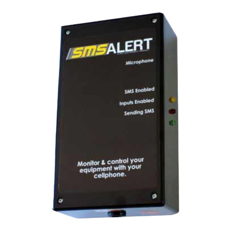
PicC Electronics SMS Alert 9 User manual

SMS Alert Alarm / Plus
Page 1of 1
The range
SMS Alert 9
SMSAlert9isdevelopedtoconnecttoanexistingalarmsystemorequipmenttobemonitoredandcontrolled.It
isa 9 input,and3 switched relay outputunitthatkeepsyouinconstantcontactwithyourhomeorbusiness.It
notifies you instantly when the inputs are triggered by sending an SMS or missed call tofour cellphones. You
can phone the unit and listen in for possible intruders. As it is bi-directional, you can also send the unit SMS
messages and control remote systems.SMSAlert 9 can be configured as a two-way intercom system using a
Base Station intercom.The input strings and phone numbers of the users are programmable by the
user.
Examples: ACLoss/Restore,motion detection; temperaturemonitoring;computer server roomcontrol;3-phase
imbalance; over/under voltage monitoring; field monitoring by using solar energy; opening of electric gates;
steamer room control & monitoring; farm water pump control and monitoring; air conditioning monitoring and
control;accesscontrol and monitoring,etc.
SMS Alert 1
SMS Alert 1 works on the same principle than SMS Alert 9, but it is smaller and less expensive. It is a
programmable dual single input,and1 switched relay outputdevice. Thedimensionsareapproximately
155mmx75mm x 55mm. It reports tofour cellphones.
Input1: (Dualoption)
Canbe setto senda SMSon bothaNegative apply or Negative remove trigger.TheSMSthatwillbesendis
Programmable.
Examples:Openyourcar with yourcellphone when youaccidentallylocked yourkey inyour car; receive a
SMSwhenyour car alarmison; activate peppergasin your car;switchboiler rooms on,etc.
SMS Alert 9 Alarm /Plus
SMSAlertAlarm / Plusisa lockup-and-go alarmanddoes not requireanexisting alarm system.It is a9 input,
1 switched relay output,LEDandSirenoutput device. Youcanarm or disarmyourSMS Alert Alarmvia
SMS,remote control orkeyswitch.It reports tofour cellphones.
SMS Alert 9 Intercom
Thisisan upgraded SMSAlert9 thatconnectstoa BPTintercom system.This system enablesyour visitorsto
callandtalk toyou fromyour intercomby pressinga button,where afteryou canopenyour gatevia SMS. The
usercan changethe phonenumber asrequired. It reports tofour cellphones.

SMS Alert Alarm / Plus
Page 2of 2
SMS ALERT ALARM / PLUS
User Manual
SMS Alert
Version 7.7
Input 1 : ZONE 1
Input 2 : ZONE 2
Input 3 : ZONE 3
Input 4 : ZONE 4
Input 5 : ZONE 5
Input 6 : ZONE 6
Input 7 : ZONE 7
Input 8 : ZONE 8
Input 9 : ** Panic **
Features
-ARM/DISARM STATUS LED
-SIREN OUTPUT
-RELAY OUTPUT
-ARM/DISARM via KEY SWITCH or SMS

SMS Alert Alarm / Plus
Page 3of 3
Quick Start Steps
1. SIM card -Insert the SIM card into the phone. Ensure the SIM card is activated.
Test this by sending a SMS and making a missed call manually from the
SMS Alert cellphone to your phone.
2. Power -Apply 12VDC.
3. Pin code -Type in the pin code that appears on your SIM card to start the phone.
4. Pin code request -This must be set to OFF (go to: Menu, Settings, Security Settings,
Pin Code Request, Enter Pin Code).
5. Auto Answer -Ensure Auto Answer is ON. This should be on by default.
6. Airtime -Ensure that the SIM-card has sufficient credit. Load airtime if necessary.
7. Message Inbox -Ensure that the phone’s inbox is empty. Once empty, the SMS Alert will
automatically keep the inbox empty.
8. SMS 1234 bfrom your cellphone to the SMS Alert. Note the yellowLED will light up when B isactive.
This step notifies the SMS Alert that it must report to the phone from which the SMS was sent. There
must be a space between 1234 and b.
9. The SMS Alert will respond by sending its status back to you (e.g. INPUT ON B---, #00000000000).
Ensure that the character “B” appears in the SMS.
How to receive your first SMS
10. ARM –Apply a positive pulse to the Key switch input for 50ms (milliseconds) and relay C will latch
(switch on or off) to indicate that the SMS Alert is armed. You will receive an “ARMED” SMS. A pilot
remote LED can be connected to this relay to indicate if the alarm is armed or disarmed.
11. Trigger Zone 1 –Apply negative powerto the Zone 1 input for 30 seconds and then remove it to
trigger Zone 1. The green LED will light for a second to indicate that a SMS is being sent
.Youwillthen
receive a “Zone 1” SMS.
12. DISARM / switch siren off –Apply a positive pulse to the Key switch input again and you will
receive a “DISARMED” SMS.
Arm / Disarm Methods
The Key input is normally open:
1. Via receiver or button -By applying a positive 12V pulse to the Key LED input
Or/And
2. Relay -Loop
positive 12V through Relay A and then back to the Key Switch
input. Then SMS: 1234 ap to arm, and again to disarm.
3. SMS 1234 c on or 1234 c off.

SMS Alert Alarm / Plus
Page 4of 4
How to program the SMS Alert to report to a 2nd, 3rd or 4th cellphone
If you want the SMS Alert to report to a 2nd cellphone, send 1234 and then the character cfrom a second
cellphone to the SMS Alert. To turn this feature off, SMS 1234 again and then the character c
from the second
cellphone.
E.g: 1234 c (There must be a space between 1234 and c. Do the same for 1234 d (3rd), and 1234 e (4th).
How to operate the relay outputs
The three outputs can be used for anything that requires remote controlling, for example to switch machinery
and equipment on and off or to open and close it, or to switch your alarm on and off.
SMS 1234 and the command to switch the relay outputs.
E.g: 1234 a on.There must be one space between 1234 and aand on,or 1234 and Aand ON.
To switch relay A on, SMS: 1234 aon, and the same for 1234 bon, 1234 con
To switch relay A off, SMS: 1234 a off, and the same for 1234 boff, 1234 coff
To switch all relays on, SMS: 1234 all on, or else 1234 all off
To pulse relay A, SMS: 1234 ap, and the same for 1234 bp, 1234 cp
Programming the input SMS strings (SMS characters):
YouareabletoprogrammetheSMSmessagesyouwouldliketoreceiveonyourcellphone/swhenyour alarm
goes off or when the inputs of the SMS Alert are triggered. Each input sends a different SMS to your
cellphone/s. Input one is usually connected to a siren through an interface relay. Input two is usually connected
to an alarm receiver so that it SMS you arm/disarm.
Important: Strings must not be longer than 20 characters, including spaces, commas, etc.
Example:If you want Input 1 to SMS you “John’s room !” when the alarm is triggered:
1. SMS 1234 1(One space between 4 and 1 and no space afterwards)
2. You get the following SMS back: Str 1 ?
3. SMS “John’s room !” ,
4. You get back a SMS Str1 OK. Do not include 1234!
Input 1 : 1234 1
Input 2 : 1234 2
Input 3 : 1234 3
Input 4 : 1234 4
Input 5 : 1234 5
Input 6 : 1234 6
Input 7 : 1234 7
Input 8 : 1234 8
Input 9 : Panic (not programmable)

SMS Alert Alarm / Plus
Page 5of 5
Howto operate the microphone to silently listen in
You are able to phone the SMS Alert and listen in for noises within a 20m radius. Phone the SMS Alert and wait
for it to auto answer. It will auto answer automatically after two rings.
Siren
If B is enabled (yellow LED on) and the unit is armed, the siren output relay will trigger for 1 minute and then
reset. E.g. the siren will switch off (time-out) after 1 minute.
General Definitions and advance information
*Advanced settings should only be changed if really needed.
1To request the
status of the SMS
Alert at any given
time, SMS 1234 r or
1234 R
The SMS Alert will respond with, for example, the following: INPUT ON B--
-, #000 #87654321
INPUT means: -Inputs1to8areenabledordisabled(exceptinput
2)
# 87654321 means: -All inputs are on.
# 00000001 means: -Input 1 is on and the rest are off.
#ABC means: -All relays are switched on.
#A00 means: -RelayoutputAisswitchedonandthe restareoff.
B---means: -Reports to one cellphone
2* Changing the
security code 1234 The default code is 1234 and can be changed through these steps:
1. SMS 1234 04 to the SMS Alert to enable it to change the code.
2. Send 1234 CODE to the SMS Alert..The SMS Alert will SMS back:
CODE ?
3. You can now SMS your selected 4 digit numeric code, e.g. 5678.
This code is used as a prefix to operate all commands.
3Panic Input This input is always on and does not depend on the Key Switch.
4Key Input This input enables or disables the 8 inputs. The Key Input is on by default
because of the red loop wire.
E.g: A relay output can be used to arm and disarm the SMS Alert from
another cellphone.
5Green LED Indicates when the SMS Alert is sending a SMS. The LED will stay on for 3
seconds. If the light is flashing, a problem exists. See troubleshooting.
6Yellow LED Indicates when B is active, e.g. the SMS Alert is now enabled. If Bis the
main user and it is off, then C, Dand Ewon’t work even if it was
programmed.
7Red LED Indicates when the Key input is enabled. When the red LED is on, all 8
inputs are ready to be triggered. Input 2 is always enabled.
8Triggering of inputs The inputs are triggered negatively by default. To change to negative
remove, SMS 1234 03. The SMS Alert will reset and power up again. This
implies for Version 7.3 and up.
9Missed Call function
This is only applicable to input 1 and for user B (first user). The missed call
function can be switched (toggled) on and off by s
ending:
1234 01
(this is

SMS Alert Alarm / Plus
Page 6of 6
function can be switched (toggled) on and off by sending: 1234 01 (this is
off by default).
Example : 1234 01. There must be a space between 1234 and 01. You
will get the following SMS back: x?xx
The return string format is [SMS for arm input | Missed Call | Relay switch
for arm input | Input swap]
10 SMS function on/off
-Arm/Disarm input
only
The SMS function can be toggled on/off by sending a 123400(thisisonby
default). This implies for Version 7.3 and up.
11 Linking the
Arm/Disarm input to
switch relay C off
(latch)
Send 1234 02 to toggle this mode. Relay C will latch when input 2 is
triggered. This can be used to arm/disarm the SMS Alert via +12V via relay
C to the Key input.
12 Loading airtime
onto the SIM card This can be done by internet (ABSA), via the keypad of the phone, or
removing the SIM-card and putting it in your own personal phone using the
voice method. Please disconnect the power from the SMS Alert when
the SIM-card is removed
13 * International code
prefix use SMS: 1234 05 to enable this. Consult your supplier. Please note that SMS
Alert has been tested in South Africa only.
Technical Specifications
1Power supply Minimum of 12 volt DC, 500mA (milliamps). Standby is 30-50mA.Youmust
at least have a battery pack inline. Auxiliary outputs on panels do not
provide sufficient power.
2Number of
cellphone users 1 -4
3Relay contacts 5A. Use additional external relays for more current. It is not recommended
to run 220 V through the relays.
4Inputs –1 to 8 These inputs are triggered when a constant negative power is removed
from the input. I.e. Put negative power on the inputs for at least 30 seconds
and remove it to SMS.
5Panic This is a Negative applied trigger 50ms and is always active regardless of
the arm/disarm status. User B must be on.
6Input –Key
Additional LED
armed/disarmed
Apply a +12VDC pulse to arm/disarm.
SMS: 1234 ap to arm/disarm.
Optional add in, and can be wired through relay C to indicate when the SMS
Alert is armed or disarmed.
7Missed Call
Burglary1This is the only input that can SMS and make a missed call when triggered.
To toggle the SMS function, send: 1234 00. To toggle the missed call
function, send 1234 01.By default it sends a SMS only.
8Service provider All cellphone networks (version 7.2 and up). Consult with Supplier for
international use.
9SMS Alert security
code The code is programmable. The default is 1234.

SMS Alert Alarm / Plus
Page 7of 7
9SMS characters SMS Alert accepts all characters if they are all upper or lower case. E.g.
1234 A ON or 1234 a on.
10 Microphone The microphone is mounted on thesideofthebox.Therangeisdependent
on the environment in which it is installed in. The “listen in” function is tested
and is audibly clear in a twenty square meter room.
11 Programmable
strings All the strings are programmable, except inputs 2 and 3.
Fault finding / Troubleshooting
1No cellphone signal If there is no network signal, go to Menu, Settings, Phone
Settings, Network Selection, and select Manual. Don’tchoose
between MTN and Vodacom, just go back to the main menu,
do the same thing over again and when you get to Network
Selection, choose Automatic.
2Flashing green LED Re-power the SMS Alert system. This happens when the SMS
Alert’spowerisconnected (reset) three times in a short period.
The automatic reset recovery is then disabled to protect the
phone until power is removed and applied again.
3Weak reception &
the aerial touching
wires
No wires must touch the aerial of the phone. The SMS Alert
won’t work inside a metal container. Use our magnetic
external extension aerials forweak reception.
4“Insert SIM-card”
error Remove the SIM-card and slightly twist the SIM-card contacts
more upward with a small screwdriver.
5Other equipment
used in conjunction
with SMS Alert
It is not recommended that other receivers, transmitters or
equipment be kept inside the SMS Alert box.
6Ad-hoc behaviour Ensure that a very good / smooth Power Supply Unit (PSU), or
power from the alarm panel is used where florescent tubes or
machinery are in the proximity of the SMS Alert. Auxiliary
outputs onpanels do not provide sufficient power.
7The green light goes
on but no SMS is
received
Make a call from the SIM card to any number -this will release
a call. You can also take out the SIM card and put it in another
phone and follow the voice prompts.
8Resetting the
system Never use the on/off button on the cell phone. Disconnect the
power of the SMS Alert and reconnect.
9Cellphone screen
dim or not working From time to time the screen might go dim. It will not prevent
the unit from working. It can be fixed manually. Please contact
us for support if it happens.

SMS Alert Alarm / Plus
Page 8of 8
Thank you for using this product!
Please note the following:
2. For software/hardware updates, please visit www.smsalert.co.za.
3. For support, phone us on 083 235 4916. Please note that your first point of call must be your
supplier or installer. If they are unable to help you, we will be more than happy to assist.
Disclaimer:
PicCElectronicswillnotbeheldresponsibleforloss,damageorinjurytoanypersons,companyor
legal entity using SMS Alert. It is also recommended that the SMS Alert is tested on a regular basis, for
example by sending a status request to it.
[1,2,3,8] [7,4,5,6]
SMS Command Summary
1234 B -Toletthe SMS Alertreportto the 1st phone(toggle)
1234 C -Reportto2nd phone (toggle)
1234 D -Report to3rd phone(toggle)
1234 E -Reportto4th phone (toggle)
1234 R -Torequestthe status oftheSMS Alert
1234 A ON –Toswitchrelay A on(andthe same forBand C)
1234 A OFF –Toswitchrelay A off(andthe same forBand C)
1234 AP-PulseRelayA once for500ms(and the sameforB and C)
1234 APP -PulseRelayA 10 times(Peppergas)
1234 01-TotoggleMissed Call functiononor off
1234 02 –Totogglethe SMS functiononor off (Onlyapplicableto SMS AlertAlarm)
1234 02 –Totogglethe dual triggermode(SMS Alert 1only)
1234 03 –
To togglethe inputs totrigger betweennegative apply(default) andnegative
remove.
Program Input Strings (max 19 characters)
12341 -String1 (Input 1)
12344 -String4
12345 -String5
12346 -String6
12347 -String7
12348 -String8
1234 9 -String9(panic)
*String2and 3 notprogrammable.Can be changedbymanufacturer.
This manual suits for next models
2
Table of contents
Other PicC Electronics Security System manuals
Popular Security System manuals by other brands

Ultra electronics
Ultra electronics HYPERSPIKE HS-14 Operation and maintenance manual

Gemini
Gemini 933 Series Installation and use manual

Hiltron security
Hiltron security TDX16 user manual

Olympia
Olympia SECURE AS 605 operating manual

Cisco
Cisco 500 Series Configuration guide

Tunstall
Tunstall MXD user manual