Page 1.2 SWITCHING MATRIX MODULE 10-510/520/530
pickering
SECTION 1 - TECHNICAL SPECIFICATION
Switching Matrix Module – 10-510/520/530
pickeringtest.com
Specifications
Switching Specification
Switch Type: Ruthenium Mercury wet †
Max Standoff Voltage: 100V 100V
Max Power:
Max Switch Current:
Max Carry Current:
20W
0.5A
1.0A
50W
2.0A
3.0A
Contact Resistance
On:
Off:
Differential Thermal Offset:
200mΩ
>109Ω
<5µV
200mΩ
>109Ω
<10µV
Capacitance:
Open Channel;
Channel-Channel;
Bandwidth (50Ω):
<6pF
<20pF
10MHz
<6pF
<20pF
10MHz
Max Operate Time:
Max Release Time:
7ms
6ms
9ms
8ms
Expected Life (operations)
Low power load:
Full power load:
>1x10⁸
>1x10⁶
>1x10⁹
>1x10⁸
† Mercury wet versions may be available to special order.
Operating/Storage Conditions
Operating Conditions
Operating Temperature:
Humidity:
Altitude:
0°C to +55°C
Up to 95% non-condensing
5000m
Storage and Transport Conditions
Storage Temperature:
Humidity:
Altitude:
-20°C to +75°C
Up to 95% non-condensing
15000m
Safety & CE Compliance
All modules are fully CE compliant and meet applicable EU
directives: Low-voltage safety EN61010-1:2010, EMC Immunity
EN61326-1:2013, Emissions EN55011:2009+A1:2010.
Mechanical Characteristics
The modules conform to the 3U height (128mm) Eurocard standard
and are 160mm deep. Panel width for all versions is 2.4 Inches.
Connectors
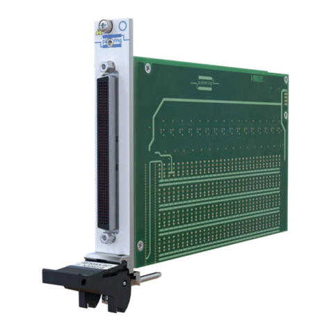
Matrix connection is via two 37-pin D-Type male connectors (one
connector for each of the X and Y axes). Please note that these
connectors are spaced closely together so care must be taken to
use mating connectors that will t on to the front panel together.
Relay Type
The module uses instrument grade sputtered Ruthenium Reed
Switches which are suitable for switching very low level signals
with a low and stable contact resistance. Mercury Wetted Reed
Switches may be available to special order. All Pickering matrix
modules allow any combination of crosspoints to be selected.
Spare Reed Relays are built onto the circuit board to facilitate
easy maintenance with minimum downtime.
All reed relays are manufactured by our sister company Pickering
Electronics: pickeringrelay.com
Programming
The Matrix module is very easy to program using the Intelligent
IEEE-488.2 Interface:
ARESET a Open all switches on device a
DIAGNOSTIC? Report any Self Test Errors
DELAY t Force a minimum delay of tmilliseconds
between two instructions
MCLOSE a,x,y Close switch at coordinates x,y on
module a
MOPEN a,x,y Open switch at coordinates x,y on
module a
RESET Open all switches on all modules
VIEW? a View status of device a
Further matrix control may be achieved using the IEEE-488.2
stored settings commands, these permit the storage and later recall
of complex matrix congurations.
Creating Larger Matrices
Each System 10 interface can directly support matrices to over
2000 crosspoints. Larger sizes are supported using multiple
System 20 matrix modules.
Large matrices are constructed by interconnecting two or more
matrix modules. All such matrix modules must have the same
primary address (up to 30 modules may have the same primary
address). Their position within the matrix is determined by their
bank address, this is set on an additional 5 way dip switch.
Pickering can build large Matrix systems constructed and tested
to your exact requirements, please contact sales ofce for further
details.
Mixed Matrix/Multiplexers Configurations
For some users requiring very large matrix systems the cost of a
“full” matrix may prove prohibitive, in many instances a combination
of multiplexer input/output and partially lled matrix may prove quite
acceptable and could be more effective in terms of both cost and
performance. Please contact Pickering to discuss your application
in detail.

