RF Multiplexer, 40-740-xx1
pickeringtest.com
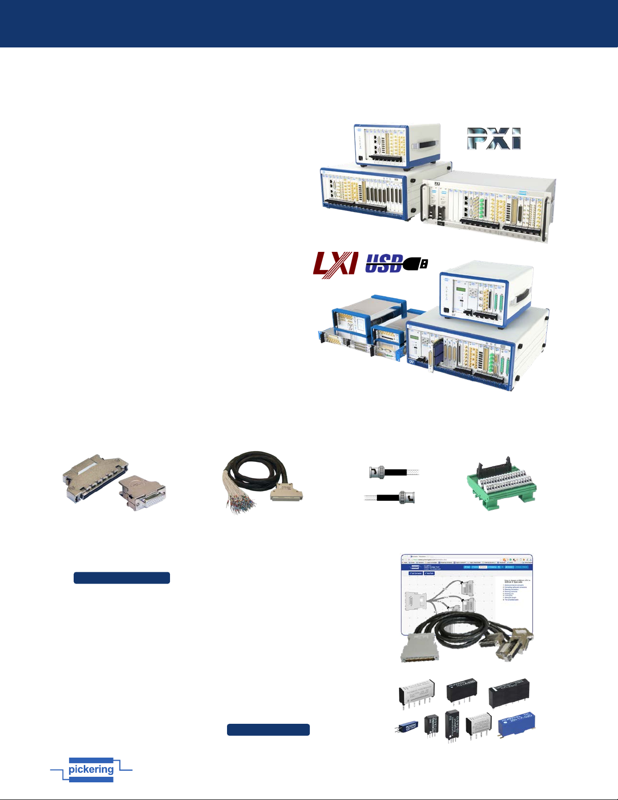
Supporting Products & Software
© Copyright (2021) Pickering Interfaces. All Rights Reserved
Pickering Interfaces maintains a commitment to continuous product development, consequently we reserve the right to vary from the description given in this data sheet.
Programming
Pickering provide kernel, IVI and VISA (NI & Keysight) drivers which are compatible with all Microsoft supported versions of
Windows and popular older versions. For a list of all supporting operating systems, please see: pickeringtest.com/os
The VISA driver is also compatible with Real-Time Operating Systems such as LabVIEW RT. For other RTOS support contact
Pickering. These drivers may be used with a variety of programming environments and applications including:
• Pickering Interfaces Switch Path Manager
• National Instruments products (LabVIEW, LabWindows/CVI, Switch Executive, MAX, TestStand, VeriStand, etc.)
• Microsoft Visual Studio products (Visual Basic, Visual C+)
• Keysight VEE and OpenTAP
• Mathworks Matlab
• Marvin ATEasy
• MTQ Testsolutions Tecap Test & Measurement Suite
Drivers for popular Linux distributions are available, other environments are also supported, please contact Pickering
with specific enquiries. We provide Soft Front Panels (SFPs) for our products for familiarity and manual control, as well as
comprehensive documentation and example programs to help you develop test routines with ease.
To learn more about software drivers and development environments, please go to: pickeringtest.com/software
Signal Routing Software
Our signal routing software, Switch Path Manager, automatically selects and energizes
switch paths through Pickering switching systems. Signal routing is performed by simply
defining test system endpoints to be connected together, greatly accelerating Test System
software development. To learn more, please go to: pickeringtest.com/spm
Diagnostic Relay Test Tools
eBIRST Switching System Test Tools are designed specifically for our PXI,
PCI or LXI products, these tools simplify switching system fault-finding by
quickly testing the system and graphically identifying the faulty relay.
To learn more, please go to: pickeringtest.com/ebirst
Three Year Warranty & Guaranteed Long-Term Support
All standard products manufactured by Pickering Interfaces are warranted against defective materials and workmanship
for a period of three years from the date of delivery to the original purchaser. Extended warranty and service agreements
are available for all our modules and systems with various levels to suit your requirements. Although we offer a 3-year
warranty as standard, we also include guaranteed long-term support—with a history of supporting our products for typically
15-20 years. To learn more, please go to: pickeringtest.com/support
Available Product Resources
We have a large library of product resources including success stories, product and support videos, articles and white
papers as well as application specific product brochures to assist when looking for the switching, simulation and
connection solutions you need. We have also published handy reference books on Switching Technology and for the PXI
and LXI standards.
To view, download or request any of our product resources, please visit: pickeringtest.com/resources