Page 1.2 RELAY DRIVER CARD 50-411A
pickering
SECTION 1 - TECHNICAL SPECIFICATION
PCI Relay Driver Card, 50-411A
pickeringtest.com
Specifications
Specification
Number of Channels: 64 Outputs
Typical Output Resistance: 0.6 Ω (on state)
Off State Leakage Current: 3 µA maximum at 12 V (start
up condition is open circuit).
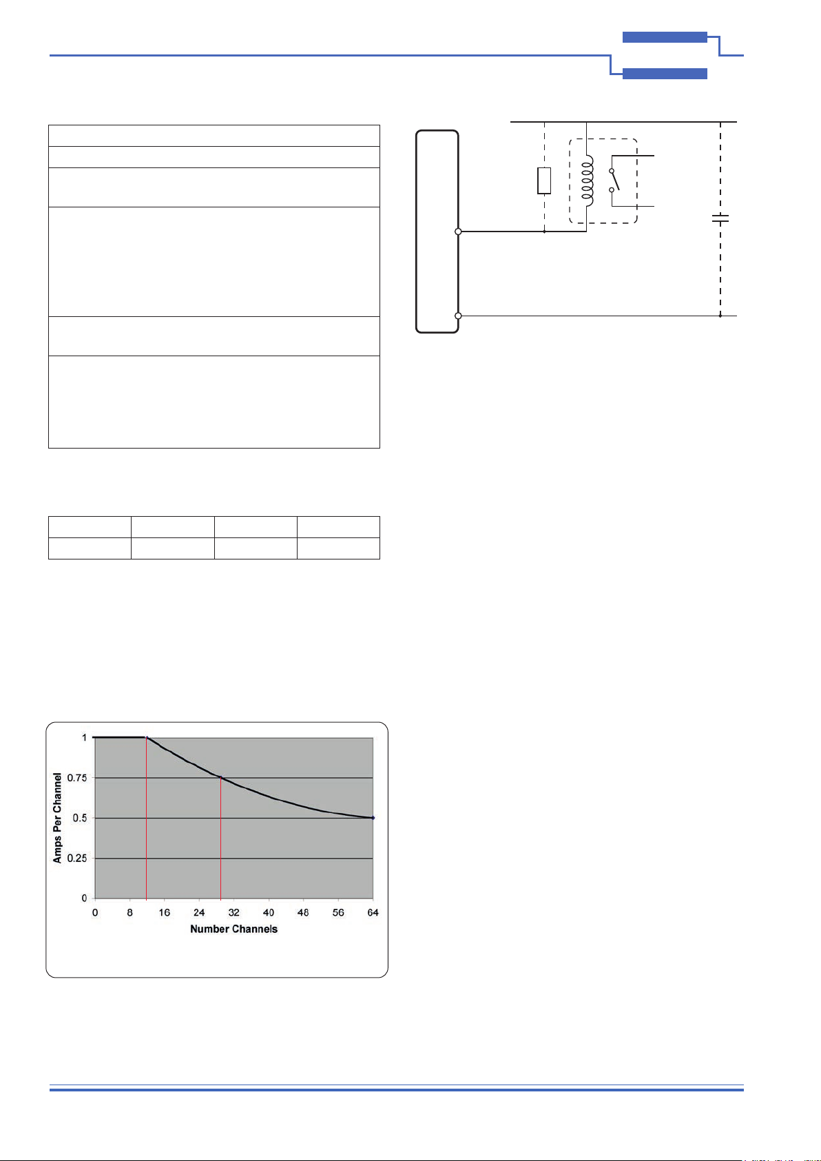
Maximum Output Current: 1 A on any channel, up to
12 channels (Please refer
to de-rating curve for lower
channel currents).
Note: for full load conditions,
adequate cooling is assumed.
Maximum Output Voltage: 60 V* (recommended max
continuous voltage).
Output Protection: Limits at 1.3 A nominal
Thermal limit activates at
typically 1.5 W in o/p device.
Overvoltage clamp operates
at 80 V.
* For full voltage rating, signal sources must be fully
isolated from mains supply and safety earth.
Power Requirements
+3.3 V +5 V +12 V -12 V
0.1 A 0 0.1 A 0
Mechanical Characteristics
Single slot short PCI format.
3D models for all versions in a variety of popular file
formats are available on request.
Connectors
Signals via a 78-pin male D-type connector, for pin outs
please refer to the operating manual.
Operating/Storage Conditions
Operating Conditions
Operating Temperature:
Humidity:
Altitude:
0 °C to +55 °C
Up to 90 % non-condensing
5000 m
Storage and Transport Conditions
Storage Temperature:
Humidity:
Altitude:
-20 °C to +75 °C
Up to 90 % non-condensing
15000 m
PXI & CompactPCI Compliance
The 50-411A card complies with the PCI Specification 2.0
(issued Feb 2004).
Signalling Environment: 33 MHz, 32-bit Universal
(+3.3 V & +5 V).
Safety & CE Compliance
All modules are fully CE compliant and meet applicable
EU directives: Low-voltage safety EN61010-1:2001,
EMC Immunity EN61000-6-1:2001,
Emissions EN55011:1998.
50-411A Derating Curve - Current per Channel
12 29
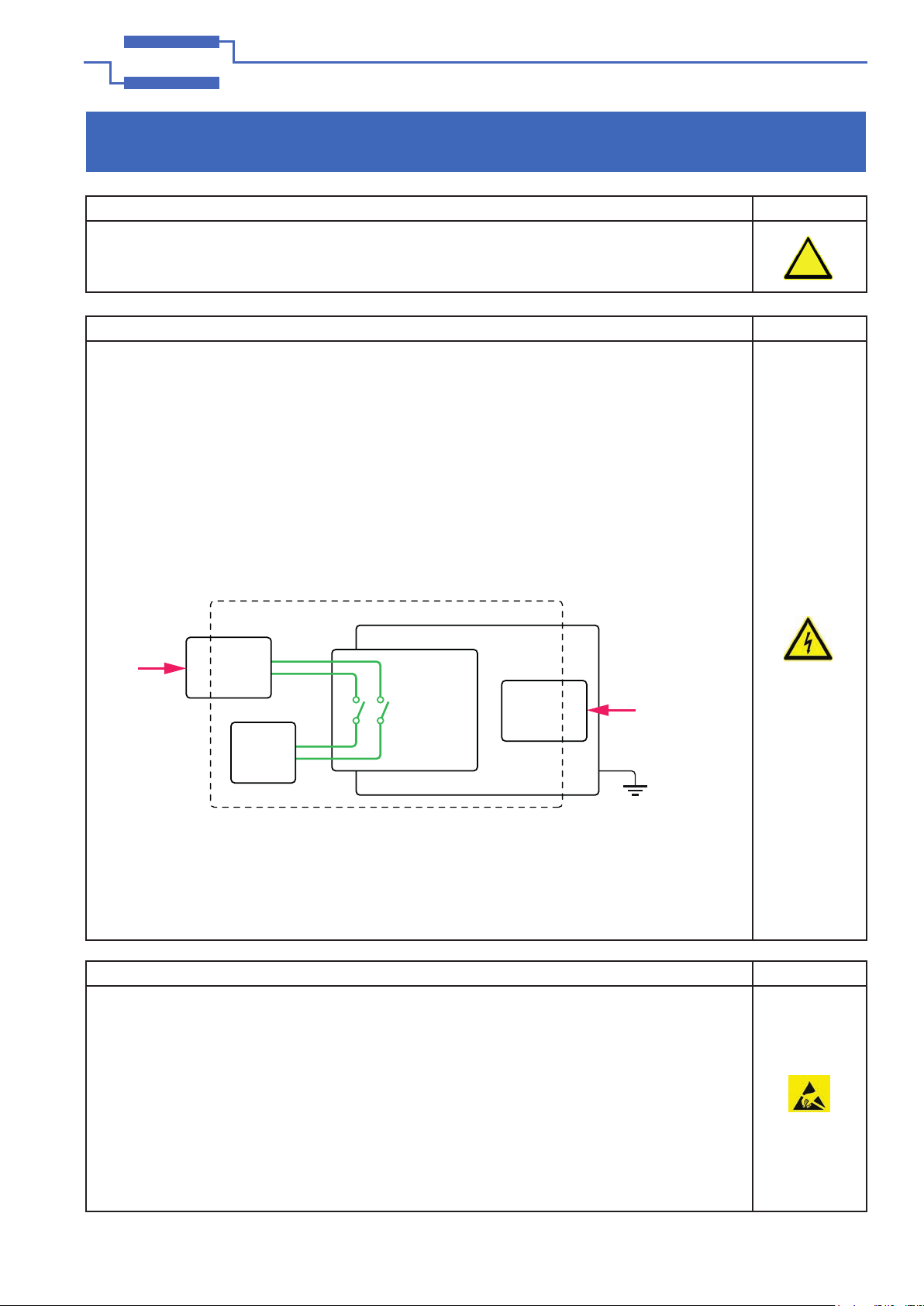
External
Relay
Power (+)
Local
Power
Supply
Decoupling
Signal
Connection
50-411A
Local Coil
Suppression
Ground Return
Using the 50-411A to drive an external relay. Local power
supply decoupling for the relay and coil suppression
circuits are recommended for best EMC characteristics
with high current relays, but are not essential for safe
operation due to the built in protection system.