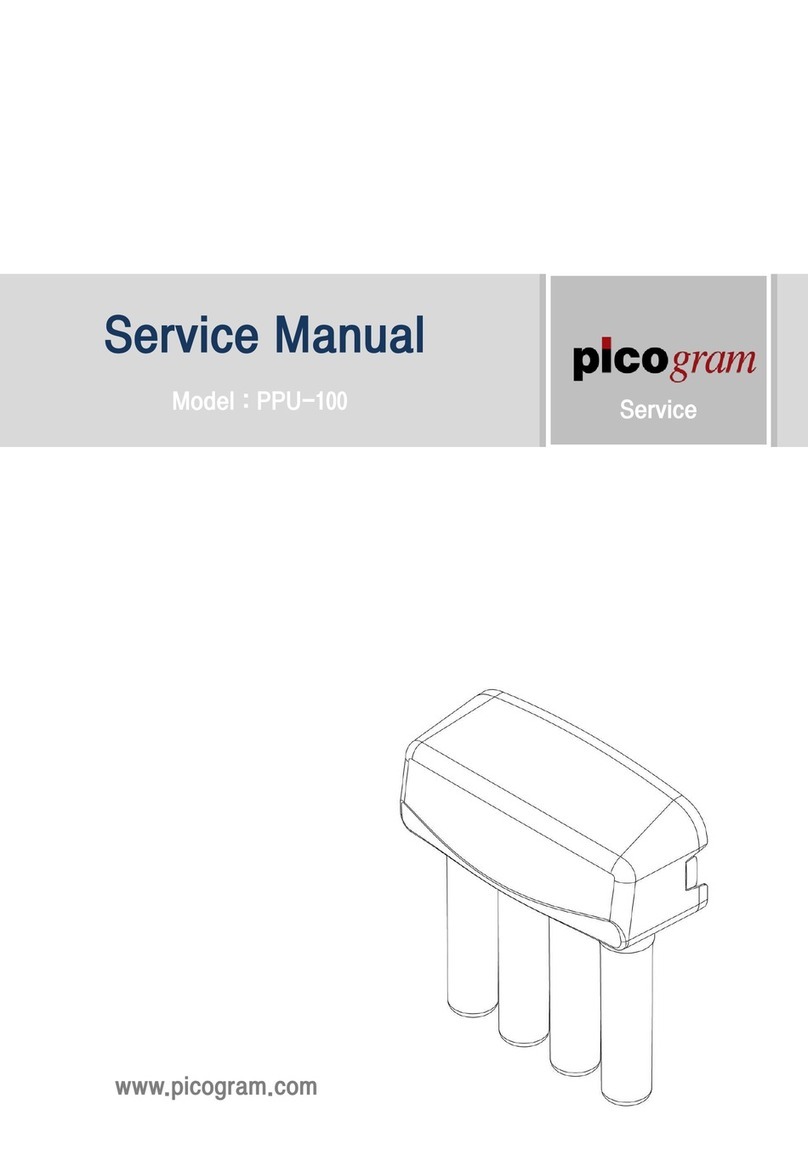
Picogram PnP Plug&Play User manual

-1-
USER MANUAL

-2-
Before using
Read this User manual for correct installation, use and maintenance
of the product. If a problem occurs while using the product, please
refer to this user manual to solve the problem. After reading, keep
this user manual with the warranty in a place that is easy to reach.
Table of Contents
1. Notice for the correct and safe use ---- 2
2. Name of Each Part (Working Drawing) --- 3
3. Product Specifications ---------------- 4
4. Preparation before installation --------- 5
5. How to Install the product ------------- 6
6. How to replace the filter -------------- 11
7. Checklist before requesting Service ---- 12

-3-
1. Notice for the correct and safe use
Danger
Warning
Caution
If the instructions are not
followed, death or severe
injury may occur.
If the instructions are not
followed, considerable
physical injury or property
damage may occur.
If the instructions are not
followed, light physical
injury or property damage
if not kept the instructions.
Warning
▩Never disassemble, repair or reconstruct.
▷This may cause failure.
▩Never press the push button or twist filers while using the product.
▷This may cause failure due to high water pressure.
▩Do not install near radiators.
▷This may cause fire, or the product could be damaged, resulting in the leakage.
Caution
▩Do not install on uneven surfaces and not apply too much force to the item.
▷This may cause physical injury or breaking of the product.
▩Lock the feed water supply valve if it has not been used for a long time.
▷Especially, during holiday season, the water pressure will rise
and it may cause leakage.
▩To drink clean water, replace the filter according to the filter replacement period.
▷If an exhausted filter is used, the function of purification could be lowered.
▩When replacing the filter or moving the product, do not pull the water supply hose.
▷The water supply hose may be removed or the coupling may be weakened.
▩If leakage occur while using the product, or the area around the product is wet,
lock the raw water supply valve immediately.

-4-
2. Name of Each Part (Working Drawing)
Fig. 1. Product working drawing
If there is a possibility hose may be bent when connecting the
hose, use the one touch elbow fittings attached to install.
hydrant
⑦faucet
sink
hot
water
cold
water
feed
water line
purified
Water line
⑥feed water
adaptor
fitting
hose
purified
water
carbon filter
incoming
water
←─ FLOW ─
①head connector
ass'y
②carbon filter
[Rear View]

-5-
3. Product Specifications
3.1 Filter size: 8", 10", 11", 13"
3.2 Purification processing
Sediment filter →Pre carbon filter →Membrane filter →Post carbon filter
3.3 Use Condition
* Feed water pressure: 0.5~4㎏f/㎠
* Feed water temperature: 4~45℃
* pH : 2.0~11.0
* Max. Flow: 4 LPM
Caution: If the pressure of raw water exceeds 4㎏f/㎠(100 psig),
it is recommended to use a pressure regulator (pressure reducing valve).
3.4 Filter function and replacement period
Classification
Sediment filter
carbon filter
Membrane filter
Post carbon filter
Function
Removes the
invisible fine
particles or rust
remnants
Removes the
remaining chlorine
or volatile organic
compound, or
odor.
Removes the fine
floating materials
more than 0.01㎛
and microorganism
Removes the odor
and improve the
taste of the water
Estimated
replacement
period
6~8 months
6~8 months
12~18 months
12 months
* Change the filter periodically. If the replacement period is exceeded,
the quality of the purifier may be lowered.
* The replacement period can be changed within the estimated replacement period
according to the quality condition of raw water.
(Filter replacement periods are applied based on 10ℓdaily use at home)

-6-
4. Preparation before installation
Caution
▩Read User Manual before installing the product.
▩This product is a home purification system using tap water as raw water.
▩
The feed water exceeding the use requirements of this product needs pretreatment.
▩Do not use water which is not safe biologically or has not been
sterilized properly.
▩The adaptor of raw water is PF1/2" screw. Check the screw specifications
of the raw water line.
▩For water service systems that are different from Figure 1, contact A/S center
to ask help for installation.
4.1 Identification of components
※Make sure that all the components are provided.
①head connector
assay
②filter 1 types
③faucet
④inlet valve
⑤screw
⑥one touch elbow fitting
⑦hose
Figure 2. Components
4.2 Installation Location Checking
1. PnP Filter System installation
It can be installed at a convenient place under a sink. However, this product should be
installed within 4ms from feed water supply valve and faucet.
2. Faucet installation
Install at a convenient place on the upper part of a sink. However, there shouldn't be
any obstacle in the space under a sink where the faucet is installed.

-7-
5. How to install the product
Caution
▩Keep to the minimum distance so that the hose connected between components
is not bent or twisted.
▩Do not install in any place that is lit by direct sunlight or exposed
in the frozen status.
▩Be sure to install in a convenient place for filter exchange or maintenance.
▩When moving or lifting the product, make sure the filter remails vertical.
5.1 How to connect the hose between components
The connection of the hot/cold water supply line, head connector assay, and the purified
water faucet can be completed simply just by using one touch fitting.
※How to use one touch fitting
Fitting is the structure where the part called 'collette' is inserted in the body as shown
in the figure below. The inside of the collette is shaped like a fishing hook that helps
the hose to stay inside to be removed if inserted.
1. Push the hose in the part assembled with collette deeply and connect (Figure 3-1, 3-2).
2. When removing the hose, pull the hose by pressing the collette as shown in Figure 3-3.
Fig. 3-1: Insert the hose into Fig. 3-2: Push the hose into the Fig. 3-3: When removing the hose,
the collette. bottom of the fitting. complete the task by pressing
the collette.
Fig. 3. How to use one touch fitting
Collette
body

-8-
5.2 How to install the inlet valve
Caution
▩First, check the screw standard of raw water supply line under a sink.
The screw of this valve is PF1/2" standard screw. (If the standard is wrong,
never construct it.)
▩Be sure to install the valve in the cold water side of the raw water line.
If installed in the hot water side of raw water line, the purification system shall
be damaged or the function can be disabled or broken.
1. Close the feed water supply valve in the
cold water side feed water line.
2. Remove the metal hose that is connected
with the sink hydrant.
3. Assemble the feed water adaptor and
valve as shown in the figure.
(Be sure to insert the rubber packing)
4. Assemble the metal hose again on the
assembled raw water adaptor.
Caution : Do not open the feed water
supply valve yet.
Fig. 4. Installation of the feed water adaptor
metal hose
assembly
Remove metal hose
feed water
supply valve
clockwise –lock
★Use the cold water side supply valve.
Valve adaptor
rubber
packing
.
Feed water
supply valve

-9-
5.3 Installation of purified water faucet
※Notices regarding selecting the location
Caution: If there are obstacles in the open area under a sink, it is not possible to install
a faucet. Be sure to check the lower part of the sink in order to install a faucet.
1. Drill the positioning hole (diameter 3~5mm) using a drill. (Fig. 5-1)
Fig. 5-1. Positioning hole drilling
2. Install the drill on a drill chuck firmly and drill a large hole (diameter 11~12mm) (Fig. 5-2)
Fig. 5-2. Big hole drilling
Caution: Use a strong speed drill for this work
Caution: Avoid a fast RPM during first drill
operation. There may be dangerous
as chips or pieces can be scattered.
Operate slowly by pressing the drill motor on
The positioning hole lightly.
Increase the motor RPM gradually.
3. Clean the chips around the hole.
You are now ready to install a faucet.
4. Insert the base washer into the screw area
under the faucet body and then insert the
faucet in the drilled hole.
5. Insert the rubber packing washer under a sink
and then fix the faucet firmly using fixing nuts
firmly.
6. Connect one touch fitting to the end of the
screw area of the faucet and connect the hose.
Fig. 5-3. Faucet installation

-10-
5.4 Installation of the head connector assay
Install in the convenient area under a sink to be apart more than 30cm (1ft) from the floor.
If installed lower, it will not be possible to install the filter. (Refer to Fig. 6)
5.5 Filter installation
Caution: Install the filter according to the procedure marked in the connector of the
head connector assay. If the procedure is changed, it may cause
a serious problem with the purification performance.
5.5.1 Twist Type
1. Arrange the filter as shown in Fig.7 and insert the filter. Push it up and insert by
turing 90 °clockwise.
5.5.2 Push Type
1. Arrange the filter in the hole of the lower part of the connector and then push it up
and insert by turning the filter.
(For Push type, if ‘Click’sounds, it means that it has been installed normally.)
2. Check to make sure that the push button is coming out normally.
(If it is not coming out, it means that the filter is not completely installed.)
Fig. 6. Attachment of the head Fig. 7-1 Installation of the Fig. 7-2 Installation of the Turn
connector assay Twist type filter type filter
②insert the
filter and
then
turn 90°
clockwise.
①match the direction of the
filter and connector as
shown in the figure.
insert the
filter into the
connector.

-11-
5.6 Hose Connection between each part
1. Connect the raw water adaptor assembled in the cold water side and the inlet hole of
head connector assay. In this case, make sure that the hose is not bent or twisted.
2. Connect the hose between the outlet hole of head connector assay and one touch fitting
connected to a faucet.
Caution: Refer to Fig. 1. Working Drawing of page 3.
5.7 System Operation and Leakage Check
Caution : Before operating the system, be sure to check if the pipe is connected
correctly and verify the installation once again. Check if the components
are connected with each other firmly.
1. Before operating the system, check the following.
The faucet should be unlocked. (Turn the faucet handle to CCW)
2. Open the raw water supply valve slowly.
After a while, check if the purified water is coming out from the faucet.
Check the leakage of each part.
3. If the purified water is coming out normally, close the faucet.
Check the leakage of each part.
4. If there is no leakage, open the faucet once again.
Let the purified water run for about 5 minutes and then lock the faucet.
5. If the water tastes abnormal or smells bad, repeat the above 4 steps.

-12-
6. How to Replace the Filter
6.1 Filter replacement (4 types are all same.)
<How to remove the filter>
1. Lock the raw water supply valve.
2. Unlock the faucet to discharge the pressure inside the system.
Caution : If the pressure inside the system is not discharged, water could be splashed
with a "POP!" sound when removing the filter.
3. To replace the filter easily, hold the filter and pull it 45°forward.
4. For the Turn type filter, remove the filter by turning it to CCW.
For the Push type filter, remove the filter by turning it in the status of pressing the push
button. (Pull the filter by turning to remove easily.)
Fig. 8-1. Turn type filter removal Fig. 8-2. Push type filter removal
<How to install the filter>
5. Remove the packing of the new filter and match the upper part of the filter with the hole of
the lower part of the connector and then insert it by turning. (Refer to Fig.7-1 and 7-2 of
page 9.)
6. When the replacement process has been completed, unlock the feed water supply valve.
7. Check if there is a leakage in the filter and the head connector assay assembly part.
8. The purified water should be running out continuously. Wait for at least 5 minutes and then
lock the faucet.
6.2 System Maintenance
Caution: To get the clean purified water, be sure to sick to the filter replacement period.
Sediment filter: 6~8 months Pre carbon filter: 6~8 months
UF Membrane filter: 12~18 months Post carbon filter: 12 months
Remove the filter by
turning it to CCW to
remove it easily.
Turn the filter to CCW
by pressing the push
button to remove
it easily

-13-
7. Check list before requesting Service
※Failure Index and Solutions
Phenomena
Causes/Checklist
Actions
The purified water
does not run.
Is the feed water supply valve
locked?
Unlock the feed water supply valve.
There is not enough
purified water.
Is the hose bent or twisted?
Be sure not to bend the hose.
Replace the bent hose.
Is the raw water supply valve
unlocked just partly?
Unlock the raw water supply valve
fully.
Did the temperature of the raw water
decreases sharply? (This is
especially applicable during the
winter)
If the water temperature decreases,
the amount of purified water shall be
reduced.
Has the life of the filter (replacement
period) run out?
Replace the filter.
Water tastes
abnormal or smells
bad.
Has the life of post carbon filter run
out?
(Check the replacement period)
Replace the post carbon filter.
Leakage of the hose
connecting area
The hose is not connected
completely.
Push the hose fully to connect it
completely.
The edge of the hose is damaged.
Cut the damaged area and connect
again or replace with a new hose.
Leakage from the
head connector
assay
Fault in the hinge O ring assembled
between the connectors
Lock the raw water supply valve and
contact the A/S center.
Table of contents
Other Picogram Water Filtration System manuals
Popular Water Filtration System manuals by other brands

Antunes
Antunes VZN-441VE owner's manual

AQUAMAXX
AQUAMAXX HOB-1 installation guide

Duramaxx
Duramaxx 10028064 manual

Nu-Calgon
Nu-Calgon NuShield-CI Installation, operation and maintenance manual

Baldwin
Baldwin DAHL 55-EK installation guide

Schaffner
Schaffner FN 6840-25-113-E0XXR User and installation manual