Picowatt AVS47-232 User manual

PICOWATT
Veromiehentie 14
FI-01510 VANTAA, Finland
phone 358 50 3375192
Internet: www.picowatt.
e-mail: reijo.voutilainen@picowatt.
AVS47-232/USB CONVERTER
For Interfacing the AVS-47B with Computers
User Guide

Page 2
Revised: 2016-03-26 AVS47-232/USB User Guide 0R1.indd
User
Guide 0R1 For Interfacing the AVS-47B with Computers
AVS47-232/USB CONVERTER
CONTENTS
WARRANTY 3
BACKGROUND 4
USB-Picobus 4
GPIB-Picobus 4
AVS47-232/USB 4
CONNECTING THE AVS47-232/USB 5
STARTING THE AVS47-232/USB 6
Re-starting the AVS47-232/USB 6
RS232 Format 6
COMMANDS AND COMMAND LINES 7
Responses 7
Send/Receive Serial tool 9
FIRST COMMANDS AND QUERIES 10
HARDWARE COMMANDS 10
MEASUREMENT AND READOUT
COMMANDS/QUERIES 11
OTHER COMMANDS AND QUERIES 14
COMMANDS FOR THE TS-530A
TEMPERATURE CONTROLLER 14
CABLE SPECIFICATIONS 16
Picobus Cable 16
Serial Cable 16
RE-PROGRAMMING THE AVS47-232/USB 16
INDEX 19

Page 3
Revised: 2016-03-26 AVS47-232/USB User Guide 0R1.indd
User
Guide 0R1 For Interfacing the AVS-47B with Computers
AVS47-232/USB CONVERTER
WARRANTY
Picowatt warrants the AVS47-232/USB hardware
to be free from defects in materials and workman-
ship. Our liability under this warranty is limited to
repairing or replacing any instrument or part thereof
which, within three (3) years after the shipment to
the original purchaser, proves defective. This war-
ranty is void if the instrument has not been used
according to the instruction manual, or if it has been
used under exceptional environmental conditions.
In need of warranty repair, the instrument must
be returned to Picowatt, prepaid , and with a detailed
description of the fault or misfunction following the
instrument.
The name, address and e-mail address of a person
who is able to give supplementary information should be
included whenever possible. If the repair was covered
by warranty, Picowatt will return the instrument on
our cost using an economical shipping method.
If no fault is found, or if there is a strong indication
that the warranty is void, the purchaser is charged for
the return freight and costs in addition to the repair. It
is recommended that Picowatt be contacted prior to
shipment. We can possibly give instructions for addi-
tional tests or simple component replacements so that
unnecessary shipments may be avoided.
The rmware must not be considered a com-
mercial product.It is given as is, for free, without
any kind of warranties or liability. The program and
this user guide may contain errors, and we would be
glad to get feedback, corrections and suggestions for
improvements.
Important: The AVS-47B uses +/- 5 Volt levels for data communica-
tions in its standard conguration, whereas the AVS47-232/USB can
be damaged by applying negative voltages to its 15-pin connector.
Therefore, short circuit piece JP204 MUST BE CHANGED to
position JP203 on circuit board “E” (the board with the power supply
unit) before connecting the AVS-47B and the converter together.
If the AVS-47B is used with model AVS47-IB GPIB box, or with the USB-Picobus LabView
programs, this jumper shall be returned to JP204.
RV-Elektroniikka Oy Picowatt
Veromiehentie 14
FI-01510 VANTAA
FINLAND
telephone +358 50 337 5192
email: reijo.voutilainen@picowatt.

Page 4
Revised: 2016-03-26 AVS47-232/USB User Guide 0R1.indd
User
Guide 0R1 For Interfacing the AVS-47B with Computers
AVS47-232/USB CONVERTER
BACKGROUND
The AVS47-232/USB is an external protocol con-
verter that creates an optically isolated RS232 inter-
face for the model AVS-47B AC Resistance Bridge.
Until now, Picowatt have offered two possibilities
for interfacing the AVS-47B with computers: The
direct Picobus interface and the model AVS47-IB ex-
ternal GPIB (IEEE-488) interface unit. Both alterna-
tives have limitations with respect to computer type,
operating system and programming language. The
AVS47-232/USB removes many of these limitations
at a low cost, offering new possibilities for computer
interfacing. A short description of the three available
interfacing solutions follows.
Some commands are for the TS-530A Tempera-
ture Controller. This product has been discontinued,
those features are only for the existing instruments.
USB-Picobus
Picobus is a proprietary synchronous, serial pro-
tocol that is based on two coming and two leaving
signal lines. Suitable four lines are provided by the
hardware handshake outputs and inputs of traditional
Com: ports of PC-type computers. The asynchro-
nous TXD and RXD signals of the RS232 interface
are not used by Picobus. Today’s computers seldom
have physical Com: ports, but a virtual Com: port
can be created by a USB-232 converter.
Unfortunately, low-level Picobus communica-
tions is complicated, as it requires computer pro-
gram to write and read states of independent bits of
some hardware registers. In order to make programs
portable between different platforms, operating
systems do not favour direct hardware access. For
this reason, we have offered driving programs (USB-
Picobus) only for a Windows-PC running Lab-
View2012 or higher (base version or better).
This has been a serious limitation that excludes
Mac computers and programming languages other
than LabView. The great advantages of Picobus are,
that the protocol is almost bullet-proof, it has low
EMI noise, and for customers with a suitable com-
puter environment, it is completely free with the
exception of a possibly needed USB-232 converter.
GPIB-Picobus
This interfacing solution is based on an external con-
verter, AVS47-IB, between IEEE-488 and Picobus
protocols.
This very powerful converter offers automatic
scanning of sensors, buffering of data and many
macro commands. The box is connected to - but gal-
vanically isolated from - the AVS-47B via Picobus
and to the computer via GPIB (therefore the name of
this option is GPIB-Picobus). It has its own mains
power supply and it can be located far from the cry-
ostat in order to minimize electromagnetic or ground
current problems that the GPIB line may cause. The
box can be used with computers having an GPIB
controller and suitable software for GPIB communi-
cations. It is highly compatible with the IEEE-488.2
standard with its mnemonic and common com-
mands and error reporting. We offer a versatile free
LabView Driver that was written for LV7.1 and can
still be used with today’s LabView versions. For the
most noise-critical applications, a 5-meter optical
bre link is available (Picolink).
The GPIB-Picobus has a much wider range of
applications than USB-Picobus, e.g. it can be inter-
faced also with Mac and Linux computers. How-
ever, for customers that do not already use GPIB, the
cost of this alternative is signicant.
AVS47-232/USB
The AVS47-232/USB is also an external protocol
converter box that is connected to the resistance
bridge via galvanically isolated Picobus. It can be
connected to the computer’s Com: port using a one-
to-one cable with 9-pin connectors. More typically,
The AVS47-IB is a protocol converter between GPIB
(IEE-488) and Picobus. It is the heart of the GPIB-
Picobus interface.

Page 5
Revised: 2016-03-26 AVS47-232/USB User Guide 0R1.indd
User
Guide 0R1 For Interfacing the AVS-47B with Computers
AVS47-232/USB CONVERTER
it is connected to a virtual RS232 port using a USB-
232 converter which enables RS232 communications
between the computer and the box. The important
difference between USB-Picobus and AVS47-232/
USB is that the former uses the proprietary syn-
chronous Picobus protocol and the latter is based on
asynchronous RS232.
RS232 is a very old protocol which has disap-
peared from many instruments because of its low
speed and poorly standardized software behaviour.
However, asynchronous serial communications is far
from dead: Most operating systems, like Windows,
Linux and Mac OS, and most common programming
languages, like C/C++, Python, versions of Basic
etc., LabView and Matlab, support it. The speed is
not an issue with slow instruments, like the AVS-
47B, which produce only tiny amounts of data. The
AVS47-232/USB expands computer-interfacing of
the AVS-47B beyond a Windows-PC and LabView
to almost any application and platform where RS232
communications is supported.
Commands and queries to the AVS47-232/USB
are simple and mnemonic, like “RAN3” for the
200Ωrange. Communications is based on the most
common default format without handshaking. There-
fore many low-cost USB-232 converters are likely to
perform well in this application.
The AVS47-232/USB is based on the very popu-
lar Arduino Mega2560 unit.
AVS47-232/USB Unit measures 130x105x60 mm and
gets power from the AVS-47B.
CONNECTING THE AVS47-232/USB
The device is connected to the AVS-47B Resistance
Bridge using the supplied 5-meter long DB25P/
DA15P cable. The AVS47-232/USB box should
be located near to the computer and far from the
cryostat. Connection from the box to the computer
varies depending on available hardware:
- Computer has a physical RS232 port:
Connect the supplied 1.5m cable with male and fe-
male 9-pin D-connectors from the AVS47-232/USB
box to the RS232 port of your computer.
- Computer has only USB ports:
You need a USB-232 converter and its software
installed. Plug the USB connector to your computer
and the our supplied 9-pin cable between the con-
verter and the AVS47-232/USB box. The USB-
The AVS47-232/USB uses 0/+5V volt-
age levels for communications with the
AVS-47B Resistance Bridge, which is set
for -5/+5V levels by default. Therefore,
open the top cover of the bridge and move
short circuit piece JP204 to position JP203
before making any connections.
The jumper must be in JP204 for use
with USB-Picobus programs and for use
with the AVS47-IB GPIB box.
Change short circuit piece JP204 to position JP203
before making any connections in order to avoid
damage to the AVS47-232/USB, which uses 0/+5V
voltage levels for communications with the AVS-47B
resistance bridge.

Page 6
Revised: 2016-03-26 AVS47-232/USB User Guide 0R1.indd
User
Guide 0R1 For Interfacing the AVS-47B with Computers
AVS47-232/USB CONVERTER
C:\Users\user\Documents\AVS47-232\Valokuvat\AVS47_232_connections.vcd 22/3/2016
ComputerwithaphysicalRS232port
5meterPicobusCable
DB25P/DA15S
1.5meterRS232cable
DE9P/DE9S1:1
AVS47-232
5meterPicobusCable
DB25P/DA15S
AVS47-232
1.5meterRS232cable
DE9P/DE9S1:1
ComputerwithoutanRS232port
USB-232
converter
USBport
There are two ways to connect the AVS47-232/USB: Either directly to
computer’s RS232 port, or via a USB-232 converter to computers USB port.
The converter creates a virtual RS232 port that your high-level program will
access.
232 converter from National Instruments (NI part
number 778472-01) is known to work well, but it is
expensive. Cheaper converters are available from
other manufacturers.
STARTING THE AVS47-232/USB
The box starts when it gets power from the AVS-47B
via the 25/15-pin cable. The “REMOTE” indica-
tor on the AVS-47B front panel is blanked. The box
starts always in local mode. Change from local to
remote or vice versa does not alter the state of the
bridge.
Re-starting the AVS47-232/USB
If needed, the box can be re-initialized by a) switch-
ing the AVS-47B off and on, or b) unplugging and
then re-connecting the 25/15-pin cable. The latter
can be used even during temperature control, be-
cause this operation does not change the states of the
bridge or the controller.
The box can be re-started by command “RST”. It
will bring the bridge to a safe setup: input=ZERO,
multiplexer channel=0, range=2MΩ, excitation=3µV
and display=R. In addition, command separator
defaults to “;” (semicolon) and response line termi-
nator to CRLF. Software reset is a less powerful
way to initialize the program than the power-off-on
method.
RS232 Format
The AVS47-232/USB uses the most common RS232
format: baud rate 9600, 8 data bits, 1 stop bit, no
parity and no ow control. This format can be
changed only by changing the Arduino rmware and
re-loading it. Do not change this format, if there is
no compelling reason to do so.

Page 7
Revised: 2016-03-26 AVS47-232/USB User Guide 0R1.indd
User
Guide 0R1 For Interfacing the AVS-47B with Computers
AVS47-232/USB CONVERTER
COMMANDS AND COMMAND LINES
It is a good idea to get acquainted with the
AVS47-232/USB by using an RS232 hypertermi-
nal program. It lets you control the bridge by writ-
ing commands/queries and reading the responses.
Although such a program is no longer included in
Windows, many free programs are available from
the Internet. For example, we have used
https://sourceforge.net/p/hypetermi-
nal/wiki/Home/
and, if you have LabView, you can try
https://decibel.ni.com/content/docs/
DOC-16284
Commands to the AVS47-232/USB are not case
sensitive. You may insert blank space(s) between the
command and argument part. Commands “ran5”,
“RAN5”, “ran 5”, “RAN 5” or “ran 5” are all
equivalent.
The rst part of a command or query can contain
only alphabetic letters. The second, argument part of
a command, is made of integral numbers. The argu-
ment part of a query is a question mark “?” like in
“RAN ?” or “ran?”.
Several commands can be placed on a single
command line. The commands/queries must have
a command separator, or delimiter, between them
(colon or semicolon, which is the start-up default).
Your own computer program can terminate the com-
mand line either by carriage return (CR or \r, ASCII
13), by linefeed (LF or \n, ASCII 10) or by CRLF.
These are called line terminators . The commands/
queries are performed in sequential order, the previ-
ous command must be completed before the next
one can be handled.
For example: “rem1;inp1;ran3;exc7” (quota-
tion marks are not parts of the actual string) sets
the bridge in remote mode, sensor measuring input,
200Ωrange and 10mV excitation. After having
waited for some seconds (settling time), one can take
the reading.
Maximum number of characters on one line,
including command separators and possible blanks,
is 60. Handling the commands starts after a line
terminator has been received. If the command line
is not terminated with CR, LF or CRLF, processing
will not start.
Do not issue further commands or queries before
all the commands/queries on the previous command
line have been executed.
Responses
The AVS47-232/USB obeys the strict principle, that
only a query can produce response. So your applica-
tion program needs not poll and read the serial port
after commands.
Responses can consist of printable alphanumeric
characters, but most queries return only a number.
Some values are output as oating point numbers,
but exponential format is not supported. The re-
sponses do not have headers in order to make them
easier to read into a program.
If a command line consists of more than one
query, the responses are output in the corresponding
order and they are separated by the specied com-
mand separator (delimiter).
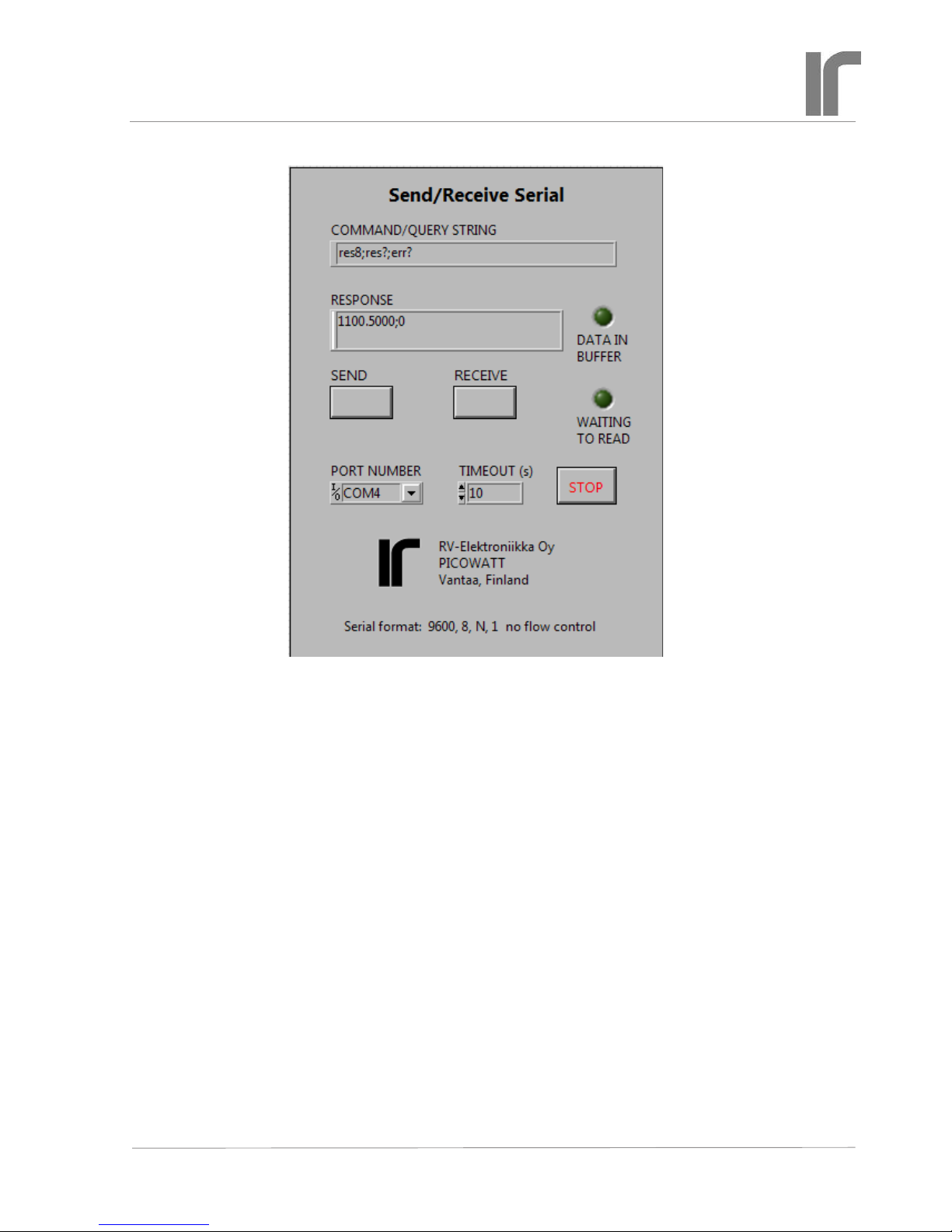
For example, command line
“ARN10;RES5;RES?;RAN?” instructs the bridge to
go to autorange mode, wait for 10 seconds after each
automatic change of range (if needed), then take a
mean of 5 A/D conversions, and place the result and
the range setting (which was possibly altered by au-
toranging) in the output queue. The result is sent via
the RS232 port to the computer, which must detect
that data has arrived and then read it or place it in a
buffer. The response could be like “1234.5;4” (i.e.
1234.5Ω; 2kΩrange).
You may save programming overhead by giving
commands for a measurement on one line. Respons-
es to queries may be easier to read into variables, if
queries are made separately. Then one does not need
to remove the delimiters and parse the response line.
The response ends by the line terminator speci-
ed by the TER command (default is CRLF). The
terminator can, but it must not, be the same for both
transmitting and receiving. The AVS47-232/USB
will always recognize any of the three line termina-
tors, CR, LF or CRLF.

Page 8
Revised: 2016-03-26 AVS47-232/USB User Guide 0R1.indd
User
Guide 0R1 For Interfacing the AVS-47B with Computers
AVS47-232/USB CONVERTER
The “Hype! Terminal” (see text for link) is easy to use: Just specify the Com port number (SetUp) and it is ready. After identica-
tion, the bridge is set for measure input, channel 0, range 2kΩ, and excitation 300µV. Then 10 A/D conversions are taken (RES10)
and the output is read by RES?. This RS232 terminal program for a Windows PC does not require LabView.
Users of LabView can also try this program (see text for link). The output includes all printing and
non-printing characters in both transmitted and received strings, which can be useful for debugging. But
otherwise it is far less convenient to use.

Send/Receive Serial tool
This handy LabView VI was written for developing
programs for the AVS47-232/USB and AVS48-232/
USB. It allows one to send commands and queries
and to read the response to queries. It requires the
base version or better of LabView2012 or later.
Check the jumper JP203 (no other short circuit
pieces) inside the AVS-47B bridge and connect the
cables as was instructed earlier. The AVS47-232/
USB starts when it gets power from the bridge. Se-
lect the correct Com port. The serial format is xed
to the most common standard, 9600,8,N,1 with
no ow control. Run the VI and click “SEND” for
sending the default IDN? query. DATA IN BUFFER
should light. Click “RECEIVE” for reading the re-
sponse. If this works, save the VI so that you do not
need to re-enter the port number when you load the
VI next time.
Use this tool for getting acquainted with the be-
haviour of the software before starting to write your
own application in whatever programming language
you prefer. This VI uses the ‘\n’ (newline) char-
acter for terminating the transmitted string, but your
program can as well use ‘\r’ (carriage return) or
\r\n or \n\r.
Dene the response line terminator by the com-
mand TER. You can see the non-printing characters
in the response if you stop the VI, click the RE-
SPONSE eld and select ‘\’ Codes Display
or Hex Display from the context menu. Start
the VI again.
If you try to receive before a response is avail-
able, the program waits until the input buffer is
non-empty or timeout occurs. See the block diagram,
how this was done. You can put the OPC? query af-
ter a time-taking long average like RES100;OPC?
The “operation complete” query places character
‘1’ in the output queue when averaging is ready. But
anyway, your program must poll the input in order to
see when you can send the RES? query and read the
response.
This VI can be downloaded from our WEB site at
www.picowatt. .
Page 9
Revised: 2016-03-26 AVS47-232/USB User Guide 0R1.indd
User
Guide 0R1 For Interfacing the AVS-47B with Computers
AVS47-232/USB CONVERTER

Page 10
Revised: 2016-03-26 AVS47-232/USB User Guide 0R1.indd
User
Guide 0R1 For Interfacing the AVS-47B with Computers
AVS47-232/USB CONVERTER
HARDWARE COMMANDS
INP [0..2 | ?] Input selector command/query.
0 = Grounded input (zero resistance)
1 = Measure the selected sensor channel
2 = Calibrate (bridge measures internal 100Ω)
INP? returns 0..2
MUX [0..7 | ?] Multiplexer channel command/
query. The bridge will need a settling time
after channel has been changed. The required
time is longer if excitation is low. Use the
DLY command after setup commands like
MUX, RAN and EXC, before starting to take
readings.
0..7 = sensor channel
MUX? returns 0..7
RAN [0..7 | ?] Range command/query
0 = no range is connected. No excitation can
run into the sensor, but output is random.
Avoid using this value in order to avoid ac-
cidental heating of the sensor when another
range is selected. If you do not know the
proper range, start from 2MΩ.
1..7 = ranges from 2Ωto 2MΩ
RAN? returns 0..7
FIRST COMMANDS AND QUERIES
All queries work in both remote and local modes,
so that you can read bridge settings although it is
in local. Commands that control the operation of
the AVS47-232/USB rmware are also effective in
both modes, whereas hardware commands to the
AVS-47B can be used only in remote. These initial
commands are for making the AVS47-IB rmware to
correspond to your application program.
IDN? Identication query. You can check suc-
cesful starting and rmware version of the
AVS47-232/USB by this query. The response
is like “PICOWATT, AVS47-232/USB, REV
0R0”
HW? Hardware version query. Returns the ver-
sion of the AVS47-232/USB hardware. The
response is like “PICOWATT, RS232PB_A0”.
The latter item is the version of the circuit
board.
AL? Alarm line query. This query transacts with
the AVS-47B bridge and checks the state of
the “AL” Picobus signal line (AL is used for
preventing multiple reads of a single A/D con-
version). Response should be 1 if the bridge is
powered, if the 25/15 pin cable is in place and
everything is OK. If the response is 0, check
that the cable is plugged and OK. Re-start
the bridge, which re-starts also the box. The
bridge should end up to local mode. If this
does not happen, or if AL? still returns zero,
contact factory.
LIM [0..1] Select the command delimiter (or com-
mand separator).
0 = semicolon (dec ASCII 59). This is the
start-up default, which is used also by the
IEE-488.2 standard.
1 = comma (dec ASCII 44). May be useful if a
comma-separated format (CSV) is preferred.
TER [0..3] Select the response line terminator. De-
pending on your computer software, you may
need to modify the default value of CRLF.
When reading the serial port, the AVS47-232/
USB rmware looks for both CR and LF, and
when either of them is encountered, the line is
considered as ended. The possibly remaining
terminator is neglected. You can modify the
response line terminator by sending the TERx
command:
0 = nothing
1 = linefeed (LF, \n, dec ASCII 10)
2 = carriage return (CR, \r, dec ASCII 13)
3 = CRLF (start-up default)
REM [0..1 | ?] Remote mode command/query. The
change from local to remote does not change
the state of the bridge: the program reads the
setup in local mode and then sends this setup
to the bridge in remote mode. Any hardware
commands sent before the REM1 command
are forgotten. The AVS-47B shows remote
mode by a yellow light on the front panel.
0 = local
1 = remote
REM? returns 0 or 1

Page 11
Revised: 2016-03-26 AVS47-232/USB User Guide 0R1.indd
User
Guide 0R1 For Interfacing the AVS-47B with Computers
AVS47-232/USB CONVERTER
EXC [0..7 | ?] Excitation command/query. Excita-
tion voltage, as the term is used in the context
of the AVS-47B, means the RMS voltage
across a sensor whose value is half of the se-
lected range. Excitation is symmetrical square
wave -shaped current at 13.7Hz.
0 = no excitation
1..7 = 3µV, 10µV, 30µV...3mV
EXC? returns 0..7.
REF [0..20000] Reference command for
deviation (ΔR) measurements. For example,
REF10000 sets the AVS-47B’s reference DAC
to 1 Volt, which corresponds to the middle of
any currently selected resistance range.
The resulting DAC voltage can be measured
by switching the ADC input to DIS3 (the
internal reference). Then issue ADCx for
measuring the output voltage of the DAC.
The programmed reference DAC has only 12
bits (0..4095), whereas the 0..20000 output of
the bridge corresponds to about 14 bits.The
reference value is therefore divided internally
by 5 for scaling it to range 0..4000. The DAC
output changes in steps of 5 digits (500μV)
and has a typical accuracy of an economical
12-bit D/A converter.
NULDEV [1..100] Null deviation command.
This is a macro command that measures
whatever was previously selected by the DIS
command and then sends this value to the
reference DAC. The argument determines,
how many A/D conversions are used for the
measurement. A longer average improves ac-
curacy if readings are noisy.
This command is intended to be used only
with DIS0. The REF POT / REF MEM front
panel switch must be in REF MEM position.
After the NULDEV command, the rear panel
DIFFERENCE BNCoutput is near to zero.
Select DIS1 for measuring the difference.
RFS? Reference source query.
The deviation signal VdR, is the difference
between measured resistance value (analog
voltage from the self-balancing circuitry) and
the reference voltage. The reference voltage,
in turn, can be either the output voltage from
the reference DAC or the voltage of the front
panel potentiometer. This selection is made by
the front panel REF POT/REF MEM -switch.
There is no remote command for changing the
switch position.
The reference DAC is programmed remotely
by sending the REFx command (see above). It
can also be programmed manually by lifting
the SET REF switch momentarily. Then the
DAC takes the displayed reading as input. De-
viation can be nulled this way manually. The
NULDEV command is for making it remotely.
In remote-controlled applications, the refer-
ence-source switch should be in REF MEM
position. You can verify this by quering RFS?.
The response is:
0 = reference DAC (reference memory)
1 = front panel potentiometer
MAG? Magnier query
The deviation voltage VdR can be amplied by
a factor of 10. Amplication is made by a sim-
ple circuit and is therefore not very accurate.
The ΔRx10 mode is suitable for recording
only small changes, not for measuring abso-
lute values. It is best when excitation is high
and readings therefore less noisy. Magnica-
tion can be selected only manually. MAG?
returns
0 = 1xΔR
1 = 10xΔR
MEASUREMENT AND READOUT
COMMANDS/QUERIES
These commands are for determining what the A/D
converter measures, for making single or averaged
A/D conversions, and for reading the result. There is
also a command for detecting the possible overload.
DIS [0..7 | ?] Display selector command
This command selects one of 8 possible volt-
ages to be measured. The current selection can
be queried by DIS?.
Use the RES command and query only when
displaying DIS0 and DIS1. The RES? query
can also be used for reading item 7 (Set point
of the old TS-530A temperature controller).

Page 12
Revised: 2016-03-26 AVS47-232/USB User Guide 0R1.indd
User
Guide 0R1 For Interfacing the AVS-47B with Computers
AVS47-232/USB CONVERTER
Then you get the set point in resistance, scaled
correctly by the currently selected measur-
ing range. However, because of the very old
design, the TS-530A set point cannot be given
in resistance but it must be given as an integer.
Refer to the “SPT” command below.
Use the ADC command and query for all
other display items than 0,1 and 7 because
the RES values are scaled by the currently
selected measuring range. The ADC? query
returns integers -19999..19999 corresponding
to its input voltages from -2V to +2V. Refer
to the AVS-47B manual for how to use the
various display items.
0= Voltage proportional to the sensor value R
1= Deviation ΔR between R and the reference
2= Adjust reference. This is the voltage from
the front panel potentiometer
3= Reference. This is output voltage from the
reference D/A converter
4= Excitation voltage. This is the approximate
excitation voltage across the sensor. Useful
only on the lowest resistance ranges and
high excitation. Can be used for estimating
current lead resistance.
5= 530A heater voltage, (amplied inside TS-
530A, negative reading)
6= TS-530A heater current (actually, voltage
across current sense resistor in volts)
7= TS-530A set point voltage (V).
ADC [1..1000 ] A/D conversion command
The A/D conversion is made from voltage that
has been previously selected for measurement
by using the DISn command. This command
can be used both in local and remote modes.
ADC1 makes one single measurement, ADCn
makes n successive measurements and cal-
culates their average. Conversions take 0.4
seconds each, rate is 2.5 conversions/second.
If the result is an exact zero, the conversion is
automatically repeated for detecting possible
overrange (because the ICL7135 ADC yields
a blinking zero in case of an overload).
ADC? A/D conversion query
This query returns the mean value of n con-
versions (see above). The conversion result
is given as an integer -19999 to 19999 for
ADC input voltages -2V..+2V. Polarity is
indicated by minus sign and it is also returned
by the POL? query. Use ADCn and ADC? at
least for measuring items 4..6, which are not
directly dependent on range. Use RESn and
RES? for measuring intems 0, 1 or 7. Items 2
and 3 can be measured using either command.
ADC overrange yields an exact zero, which
can be distinguished from a real zero ONLY
by checking the OVL? response. See also
OVL? and ARN.
RES [1..1000] A/D conversion command for
resistance.
The ADC reading is scaled by the currently
selected resistance range, therefore measure-
ment of display items 4-6 can produce mis-
leading results.
RES1 makes a single conversion, RESn
makes n successive measurements at 0.4
second intervals and their mean value is calcu-
lated.
If the A/D converter outputs an exact zero, the
conversion is repeated for detecting a pos-
sible overload. The OVL? check should be a
routine part of your application program.
RES? Query for resistance
Resistance is output as a oating point number
with four decimal places for R and ΔR dis-
plays, and with ve decimal places for 10xΔR
display. It is scaled by the currently selected
resistance range. The reading may include a
preceding minus sign. Exponential form is not
supported.
POL? Polarity query
The ADC? and RES? return values are preced-
ed by a minus-sign if the reading is negative.
You will probably not need this query, it is
used by the rmware. POL? returns
0= negative
1= positive
OVR? Overrange query.
An overrange-reading from the ADC is an
exact zero, which would be impossible to
distinquish from a true exact zero. An internal
alternating signal makes it possible to sepa-

Page 13
Revised: 2016-03-26 AVS47-232/USB User Guide 0R1.indd
User
Guide 0R1 For Interfacing the AVS-47B with Computers
AVS47-232/USB CONVERTER
rate these two cases. However, it requires that
each zero reading must be repeated once. The
AVS47-232/USB does this automatically.
If n in ADCn or RESn is greater than
1, the average may contain one or more over-
range- readings. Overrange detections are
internally OR’ed together so, that the nal av-
erage can be seen faulty even if there is only
one single overrange reading in it. Such an
average is distorted and it should not be used.
If there is any possibility for such a situation,
use autoranging. It will react to the rst over-
ranged conversion and, after the selectable
delay, averaging is re-started. This quarantees
a correct mean value. OVR? returns
0= no overrange
1= reading was overrange, or at least one sam-
ple in the average was overrange.
ARN [0..30] Autorange mode command.
In autorange mode, each A/D conversion
result is compared against two limits:
• If lower than 1800 (out of 19999), range is
changed downwards, provided that it is not
already 2Ω.
• If the reading is higher than 19900, the range
is changed upwards, provided that it is not
already 2MΩ.
• If the argument in ADCn or RESn is greater
than 1 (average of many conversions), the
rst encountered overloaded or underranged
conversion causes an autoranging operation,
and after a delay, averaging is started from the
beginning. This guarantees a correct average.
The ICL7135 ADC circuit is overloaded, if
reading exceeds 19999. Then the AVS-47B
front panel display shows blinking zeros and
an internal overload indicator blinks between
true and false. During overload, a measure-
ment like ADC;ADC? returns an exact zero,
which cannot be distinguished from a real
exact zero.
Because of this uncertainty, the AVS47-
232/USB repeats once any conversion that
returned zero, which enables detection of
overload. The overload indicator is set to 1
(queried by OVR?).
ARN 0 means manual ranging. Argument
higher than 0 enables autoranging. A value
between 1 and 30 determines, in seconds, how
long the system waits, after having changed
the range, until measurements can be started
again, or until a new autorange operation can
take place, or until any new command can be
performed. A time like 5 seconds may sufce
at high excitations, when the bridge settles
quickly. A longer time, up to 15-20 seconds,
should be used at the lowest excitation in or-
der to guarantee good balance before readings
are taken.
If the resistance changes several dec-
ades, which is typical when switching chan-
nel, the settling delay time of x seconds is
applied after each change of range. This can
make scanning unnecessarily slow or too fast.
You can avoid this by storing in your own
program the last used range and excitation
settings for each scanned channel. Disable
autorange and set excitation to 3µV before
selecting a new channel, send the saved previ-
ous good settings to the bridge, wait for set-
tling (DLYz) and nally re-enable autorang-
ing. This will speed up scanning, if sensors
have very different values. You can still be
sure that there are no over- or underranged
readings.
Use the RAN? query if you want to check the
possibly changed range.
Autoranging is especially useful in scanning.
If you do not use autoranging, you MUST
check with OVR? whether the single conver-
sion or the average contained overload.
NOTE: The AVS-47B’s hardware autorang-
ing must not be enabled when the bridge is
under remote control. This would cause a rival
condition.

Page 14
Revised: 2016-03-26 AVS47-232/USB User Guide 0R1.indd
User
Guide 0R1 For Interfacing the AVS-47B with Computers
AVS47-232/USB CONVERTER
OTHER COMMANDS AND QUERIES
OPC? Operation complete query
This query can be placed after slow opera-
tions, like long averaging. When encountered,
it places a “1” into the output queue. It should
be the last item on a command row.
DLY [0..30] Delay command
The argument is delay time in seconds. Use
DLY for giving the AVS-47B time to settle
after a change in channel, range or excitation.
Note that autorange has its own settling delay
after each change of range before starting to
make A/D conversions. This delay is deter-
mined by n in ARNn (see ARN).
RST Reset command
This command works only when the program
is idling, i.e. it is not extracting commands
from a previously received command line or
performing those commands. RST cannot be
used for stopping long averaging.
The RST command sets the AVS-47B into a
safe state: input 200Ω, channel 0, range 2M,
excitation 3µV and display to R (resistance).
Response line terminator is CRLF and com-
mand separator is semicolon. The AVS-47B
is left in local mode, which is shown by the
blanked REMOTE light.
RST works differently than initial power-on
start: both leave the bridge in local mode, but
start-up does no alter the previous local-mode
settings whereas RST changes settings to
“safe values”.
ERR? Error query
The AVS47-232/USB has only weak error
reporting capability. Errors are not reported
automatically, they must be queried.
If the letter part of a command or query is
misspelled, the ERR? query returns “com-
mand (or query) xxx not recog-
nized”.
Arguments, which fall outside their speci-
ed limits, are coerced to those limits. The
ERR? query then returns “argument in
XXX exceeds maximum” or “argu-
ment in XXX less than minimum”.
The error register is cleared by issuing
ERR?.
COMMANDS FOR THE TS-530A TEM-
PERATURE CONTROLLER
The TS-530A is a very old design, and it has
been recently discontinued. We offer now a
low-cost analog temperature controller option
for the AVS-48 bridge. However, the AVS47-
232/USB includes also the basic commands
for the TS-530A. They are for customers,
who already have this controller. These com-
mands have no corresponding queries. The
analog setpoint voltage, the heater output volt-
age and the heater current can be measured
by the A/D converter of the AVS-47B bridge
(see the DIS command and refer also to the
TS-530A and AVS-47B manuals).
The TS-530A must be connected to the AVS-
47B with the supplied 37-way ribbon cable for
data and with the supplied short BNC-BNC
coaxial cable for the analog output from the
bridge.
The TS-530A does not have a separate
“remote” mode. Neither can the front panel
settings be read remotely. This means that one
can -but should not- change the remotely pro-
grammed PID settings by using the TS-530A
front panel switches, and the rmware has no
way to detect it. If this appears to be a prob-
lem, write your program so that the settings of
the TS-530A are updated frequently. Re-pro-
gramming the existing settings will not disturb
the analog control circuitry in any way.
SPT [10..42000] Set point command
Set point is given as a long integer. One digit
corresponds to 100µV and the range is from
1mV to 4.2 Volts. The slow integrating D/A
converter of the TS-530A is very accurate and

Page 15
Revised: 2016-03-26 AVS47-232/USB User Guide 0R1.indd
User
Guide 0R1 For Interfacing the AVS-47B with Computers
AVS47-232/USB CONVERTER
linear, but it does not go to exact zero, there-
fore 1mV is the minimum. Arguments less
than 10 are coerced to 10. Maximum value
for the converter is 4.2Volts, corresponding to
42000, but only 2 Volts maximum is meaning-
ful with the AVS-47B.
If you want to give the set point in resist-
ance, you must scale and convert it yourself
to a long or unsigned integer suitable for this
converter. For example, SPT10000 produces
1 Volt setpoint. If the AVS-47B measures on
range RAN, calculate the set point integer
from set point resistance RSas follows:
SPT = RS/ (10 ^ (RAN-1)) * 10000
where RS=setpoint in ohms
If desired set point is e.g. 110
ohms and range=200R, (RAN=3)
SPT = 110/(10^(3-1)) * 10000 =
11000
PRO [0..11] Proportional gain command
Gain increases in steps of ve decibels. Values
are very approximate.
0..14: 5-10-15-20...60dB
15: no gain. Input of the proportional ampli-
er is connected to ground.
ITC [0..15] Integrator time constant command.
Values are very approximate.
0: integrator is reset to zero. P and PD mode
control
1-10: 1-2-5-10-20..1000s. Higher number
means weaker integration
11: analog integrator is latched by leaving its
input open
12..15: integrator is reset to zero. Same as
ITC=0.
DTC [0..7] Derivator time constant command.
Values are very approximate.
0: No derivation. P and PI mode control.
1..7: 1-2-5-10-20-50-100s
Higher number means stronger derivation.
High proportional gain with strong deriva-
tion leads easily to oscillation of the control
system.
BIA [0..5] Power bias command
Power bias can be used to reduce control error
in P and PD modes. It is not useful in PI or
PID modes.
0..5: 0-20-40-60-80-100% of maximum
heater power. The highest setting is suf-
cient for maximum output on the selected
heater range when proportional input is
zero and integrator is reset.
POW [0..7] Heater power range command
Power ranges are calculated for a 100Ωheater.
If heater resistance is higher, output voltage
compliance (about 10V) will reduce the maxi-
mum power. If heater resistance is lower, the
available output current (100mA) will reduce
the maximum possible output.
0: Heater output is disabled
1..7: 1μW-10μW-100μW...1W
The heater output stage has seven current
sensing resistors 10kΩ, 3.16kΩ, 1kΩ, 316Ω,
100Ω, 31.6Ωand 10Ωcorresponding to heater
ranges 1μW..1W. One volt across a sensing
resistor means full output of the range. Based
on the above gures, you can calculate correct
ranges for heaters other than 100Ω. Similarly,
you can measure the output current using
DIS6 and calculate the heating power from
RH*I2.

Page 16
Revised: 2016-03-26 AVS47-232/USB User Guide 0R1.indd
User
Guide 0R1 For Interfacing the AVS-47B with Computers
AVS47-232/USB CONVERTER
CABLE SPECIFICATIONS
The AVS47-232/USB comes with two cables, Pico-
bus Cable and Serial Cable. The 5 meter Picobus
cable connects the converter to the AVS-47B and
the 1.5 meter Serial cable connects the box to the
computer directly or via an USB-232 converter. This
Picobus cable is distinguished from the Picobus
cable that is supplied with the AVS-47B by its male
25- and 15 pin D-connectors. The resistance bridge
is supplied with a cable that has male and female 25-
way D-connectors.
Picobus Cable
The male DB25P and male DA15P are connected
by a braided (shielded) cable with 6 conductors (e.g.
Tasker C6015). Length: 5 meters.
Note that the shielding braid must remain isolated
from everything inside the 15-pin connector shell. A
100nF ceramic capacitor with shortest possible leads
connects the braid to the connector shell. The braid
is connected to the shell of the 25-way connector at
the AVS-47B end.
This arrangement prevents the cable from act-
ing as an antenna at high frequencies while not
providing a path for ground currents at the mains
frequency. Inside the AVS-47B, Picobus signals and
its power supply are galvanically isolated from the
bridge ground .
DB25P DA15P Description
1 - braid grounded only in DB25P
4 4 CP clock from box to bridge
5 5 DI data from bridge to box
6 6 AL alarm line from bridge to box
7 7 Isolated ground
20 15 DC data from box to bridge
9 9 Isolated +5V (referred to pin 7)
Other pins are unused.
DE9S
DE9P RS232 Description
1 - -
6 DSR AL for Picobus applications
2 RXD RS232 output box=>computer
7 RTS CP for Picobus applications
3 TXD RS232 input computer=>box
8 CTS DI for Picobus applications
4 DTR DC for Picobus applications
9 -
5 Computer ground = shielding braid
Shielding braid is connected, in addition to pins 5,
also to both connector shells.
RE-PROGRAMMING THE AVS47-232/USB
Serial Cable
The male DE9P and female DE9S are connected
by a braided 1:1 cable of 6 conductors (e.g. Tasker
C6015). Length: 1.5 meters.
The rmware can be updated by reprogramming the
Arduino Mega2560 board. In order to do this, you
need
- a USB cable (type A/B)
- Arduino development software for Mega2560. This
can be downloaded from Arduino WEB site.
- The new rmware version. It is available from us.
1. Follow Arduino’s instructions to download
and install their software, start it and select the

LabView is a trade mark of National Instruments, USA.
Page 17
Revised: 2016-03-26 AVS47-232/USB User Guide 0R1.indd
User
Guide 0R1 For Interfacing the AVS-47B with Computers
AVS47-232/USB CONVERTER
Arduino Mega board type.
2. Open the four screws holding the “front”
panel of the AVS47-232/USB, the panel with
the DA15 connector. There must be no cable
from this connector to the AVS-47B. Plug the
“A” type connector into the USB connector of
your computer and the “B” end into the “hid-
den” USB connector inside the AVS47-232.
The box will now start, as it gets power from
the USB.
3. Open the downloaded new version of the
“avs47_232_USB” software (“sketch”, as they
call it). From the Sketch menu, select UP-
LOAD. If you do not get any error messages,
updating has been done in few seconds. You
can now detach the USB cable, x the rear
panel and connect the 25/15 Picobus cable
to the resistance bridge. Then test the new
rmware using an RS232 terminal program or
your own software.
Before asking us to email an updated version, please
check and tell us your old rmware version so, that
we can send to you also the old version for backup.
RV-Elektroniikka Oy Picowatt
Veromiehentie 14
FI-01510 VANTAA
Finland
e-mail: reijo.voutilainen@picowatt.
WEB: www.picowatt.

DECLARATION OF CONFORMITY
Manufacturer: RV-Elektroniikka Oy Picowatt
Address: Veromiehentie 14
01510 VANTAA
Finland
Telephone: +358 50 337 5192
E-Mail: reijo.voutilainen@picowatt.
declares that under our sole responsibility
Product Name: AVS47-232/USB Converter
Product Description: Protocol Converter between the Picobus Primary interface of the
AVS-47B Resistance Bridge and RS232 or USB port of an external
computer.
is in conformity with the following Directives:
2004/108/EC: Electromagnetic Compatibility
2011/65/EU: ROHS Directive
and that the following harmonized standards have been applied:
EN 50 081-1: Generic emission standard, Part 1: Residential, commercial and
light industry
EN 50 082-1: Generic immunity standard, Part 1: Residential, commercial and
light industry
EN 50 581: ROHS
Additional information: This product uses only +5V power, which it gets from the
AVS-47B Resistance Bridge.
Vantaa, 14 March 2016 RV-Elektroniikka Oy Picowatt
Reijo Voutilainen
President

Page 19
Revised: 2016-03-26 AVS47-232/USB User Guide 0R1.indd
User
Guide 0R1 For Interfacing the AVS-47B with Computers
AVS47-232/USB CONVERTER
INDEX
A
ADC 12
A/D conversion command 12
AL 16
AL? 10
Alarm line query 10
AL Picobus signal line 10
Arduino 5
Arduino Mega2560 5, 16
Argument part 7
Asynchronous 5
Autorange mode 13
Autoranging 14
AVS47-232 4
AVS47-IB 4
AVS-48 Resistance Bridge 14
B
Background 4
BIA 15
Bias power command 15
Blinking zero 12
Blinking zeros 13
C
Cable specications 16
Carriage return character 9
Case sensitivity of commands 7
Coercing 14
Command delimiter 7
Command delimiter cmd. 10
Command line 7
Command part 7
Command separator 7
Comma-separated format 10
CP 16
CTS 16
Current sensing resistors 15
D
DC 16
D-connectors 16
Delay 13
Delay command 14
Delimiter 7
Derivator time constant cmd. 15
Deviation 11
DI 16
DIFFERENCE output 11
DIS 11
Disable heater output 15
Display selector cmd. 11
DLY 10, 13, 14
DSR 16
DTC 15
DTR 16
E
ERR 14
EXC 11
Excitation command 11
Excitation voltage 12
Exponential format 7
G
GPIB-Picobus 4
H
Hardware version query 10
Heater current of TS-530A 12
Heater power range cmd. 15
Heater resistance 15
Heater voltage of TS-530A 12
HW? 10
Hyperterminal 7
I
Identication query 10
IDN? 10
IEE-488.2 10
INP 10
Input selector command 10
Integrator time constant cmd. 15
Isolation, galvanic 4
ITC 15
J
Jumper JP203, AVS-47B 9
L
LabView 4, 9
LIM 10
Line terminator 7
Line terminator command 10
Linux computer 4
Local 14
M
Mac computer 4
MAG 11
Magnier query 11
Multiplexer channel cmd. 10

Page 20
Revised: 2016-03-26 AVS47-232/USB User Guide 0R1.indd
User
Guide 0R1 For Interfacing the AVS-47B with Computers
AVS47-232/USB CONVERTER
MUX 10
N
Newline character 9
NULDEV 11
O
OPC 14
Operation complete query 14
Overload 13
Overrange 12
Overrange query 12
OVL 12
OVR 12, 13
P
Picobus 4
Picobus cable 16
POL 12
Polarity query 12
POW 15
Power bias command 15
Power-on start 14
PRO 15
Proportional gain command 15
Protocol converter 4
Q
Query 7
R
RAN 10
Range command 10
REF 11
Reference command 11
REF POT / REF MEM 11
REM 10
Remote mode 14
Remote mode command 10
Re-programming AVS47-232 16
RES 11, 12
Reset command 14
Resistance measurement cmd. 12
Response headers 7
Responses 7
RFS 11
RS232 format 5, 6
RST 6, 14
RTS 16
RXD 16
S
Safe state 14
Scanning 4, 13
Send/Receive Serial 9
Serial cable 16
Serial format 9
Set point command 14
Set point of TS-530A 11
set point voltage of TS-530A 12
SET REF switch 11
Settling time 10, 14
Short circuit pieces 5
SPT 12, 14
Synchronous 5
T
TER 7, 9, 10
TS-530A 14
TXD 16
U
Underrange 13
USB-232 converter 5
USB-232 Converter 4, 16
USB cable 16
USB-Picobus 4
V
Voltage levels 5
W
Warranty 3
Table of contents
Other Picowatt Media Converter manuals
Popular Media Converter manuals by other brands

Advantech
Advantech B+B SmartWorx IMcV-Giga-FiberLinX-III user manual

AmazonBasics
AmazonBasics B07MC81KYG manual

Ocean Matrix
Ocean Matrix OMX-COMPVGA-HDMI user manual

SABINE
SABINE BACKTRAK BT-300 manual

Amphony
Amphony microFIDELITY 250 User and installation guide

Transition Networks
Transition Networks T1E1-CF-01 user guide