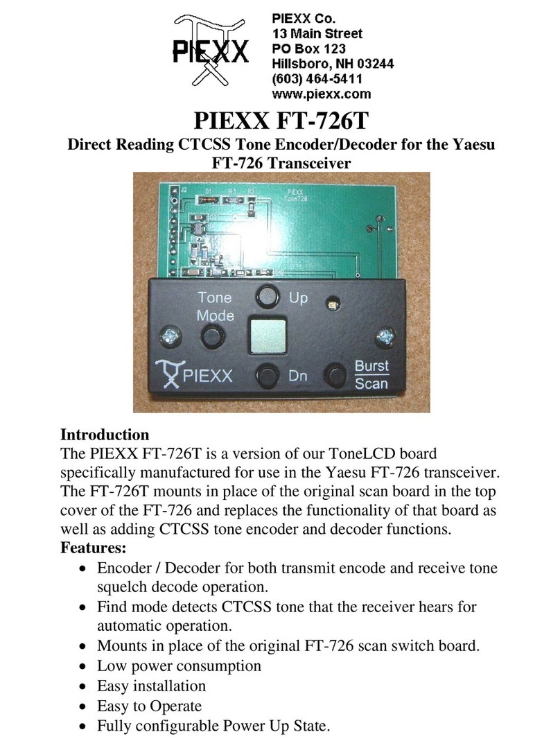
PIEXX ToneLCD User manual

PIEXX ToneLCD
Universal Direct Reading CTCSS Tone Encoder/Decoder
Introduction
If you are like me, you hate looking up dipswitch settings for tone
encoder / decoder boards. The design goal that motivated the
ToneLCD was to come up with a miniature, full feature CTCSS
encoder / decoder that was easy to use. The ToneLCD is a small,
1.125 x 1.7 inches, easy to use, full-featured tone board that has a
miniature LCD that displays the operating tone!
Features:
•Encoder / Decoder for both transmit encode and receive tone
squelch decode operation.
•Find mode detects CTCSS tone that the receiver hears for
automatic operation.
•Small size, 1.3 x 1.8”
•Low power consumption
•Operates from 4-15VDC
•Dedicated detect output as well as audio path switch.
•Easy to Operate
•Fully configurable Power on State.

Connection to Transceiver
The pin out for J2, an 8 pin interface connector is as follows:
1. Receive Audio Output
2. No Connection
3. Tone Output
4. Tone Detect
5. Ground
6. Hang Up / Xmit Input
7. Audio In
8. Power 4-15 VDC
The power required for the ToneLCD is +4 to +15 VDC at approximately 9
mA. The power lead, pin 8 of J2 should be connected to a convenient
switched supply within your transceiver. The return connection for the
power is on J2 pin 5.
In order for the ToneLCD to operate in a tone squelch mode, it needs to
sample the detected audio and provide a way to disable the audio path in the
squelched condition. The ToneLCD provides an open collector transistor
output that can be connected into your transceivers circuitry to enable or
disable the audio path. An easier way to take care of both the tone input and
squelch requirements is to connect the ToneLCDs audio in, J2 pin 7 and
audio out, J2 pin 1, in series with the hot lead of your rigs volume pot. The
ToneLCD has an audio switch in line with this audio path, and this switch is
deactivated by the ToneLCD firmware when the tone squelch is activated
and the correct tone signal is not seen. The connection in a typical
transceiver is outlined in the schematic shown in figure 5. If you have no
need for tone squelch, simply connect J2 pin 7 to the high side of the volume

control and leave J2 pin 1 unconnected. If you do not connect the audio in
signal to the ToneLCD, the device will not be able to detect and report the
CTCSS tone being used with its FIND mode.
Fig. 1
ToneLCD
Receive Audio Connection
The tone output is available from the Uncoder on connector J2 pin 3. If your
rig has a connection point for a tone generator, you should connect the tone
out to it. Otherwise, connect J2 pin 3 to a point in the transceivers close to
the modulator and past the mic conditioning circuitry. The tone output level
from the ToneLCD can be adjusted to about 1V RMS if necessary. Often a
good point to inject the tone output is the high side of the deviation control.
If you must connect the tone output to a point in the transceiver near the mic
input you may need to install a series resistor in line with it to reduce the
tone signal level so that it won’t swamp out the modulator
The ToneLCD has an input signal, on J2 pin 6, that can be used as either a
transmit detector input or a hang up switch input. If the input is used as a
transmit detector, the CTCSS tone output will only be present when the
input line is asserted. Alternatively if you have a mic holder that is switched,
you can connect the input signal to it and when you unhook the mic the tone
squelch will be defeated allowing you to hear the channels activity. If the
input is used as a hang up, the receive audio path will be made, regardless of
the presence of a valid CTCSS audio tone, whenever the input line is
asserted. In the transmitter detector mode, P2 pin 6 should be connected to
either the PTT line on your Mic plug, the transmit indicator light or a
switched Xmit power connection. In the hang up mode, P2 pin 6 should be
connected to your mic hang up switch. Don’t worry about the polarity of the
signals; the input polarity can be switched in one of the setup menus.

Set up
After you have installed the ToneLCD on your transceiver, and applied
power, the display should show
tOn
briefly, and then it will show different
information depending on how the ToneLCDhas been set up.
You will need to adjust the setup parameters to match your hardware
configuration. To enter the setup mode, press and hold the
MODE
button,
for about 1 second, until the first setup parameter,
InH or InL
, appears.
Once in the setup mode, you can cycle through the various setup parameters
by momentarily pressing the
MODE
button (don’t hold it, that gets you out
of setup). Each time you press the
MODE
button, the program cycles to the
next setup parameter. Pressing the
Up
or
Down
buttons will change the
value of a parameter. The setup parameters are defined as follows:
•
In (H or L)
– This sets the active polarity of the Input signal
line. L means low, and requires that the input signal be
grounded to be active. H indicates that the active input state is
high or floating.
•
In (r, t or
-) – This parameter sets the purpose of the input
signal.
r
is for receive, or more specifically for hang up mode.
t
is for transmit, this allows the input to be used to enable or
disable the CTCSS output tone. Finally, if this parameter is set
to
-
, the input signal is unused.
•
tO (H or L)
- Tone Detect output state. If the tO state is set to
L, the Tone Detect output will be pulled low in the presence of
a valid CTCSS tone applied to the audio input. If the tO state is
set to H, the Tone Detect output will be floating (high if you
pull it up with a resistor) in the presence of a valid CTCSS tone
applied to the audio input. The Tone Detect output is an open
collector transistor output.
•
tSt
– This is a test mode that allows you to see the state of the
input signal as well as letting you change the state of the Tone
Detect Output signal. You enter the test state by pressing either
the
Up
or
Down
buttons when the
tSt
display is shown. When
you enter the test mode, the display will change to
I-O
where
the I will be either a 0 or a 1, indicating the state of the input
signal, and O will be either H or L indicating whether the
output state is High (floating) or Low. Pressing the
Up
or
Down
buttons will flip the state of the Tone Detect Output.
Pressing the
MODE
button will leave the test mode and the

display will revert back to showing
tSt.
If you leave the
ToneLCD in the test mode for more than 60 seconds, the device
will automatically leave the Setup mode without saving any
changed parameters.
•
LCd –
This setup parameter is used to flip the LCD display
upside down, as well as reversing the Up and Down switch
functions. This is useful if you are mounting the ToneLCD in
different orientations.
•
Axx –
Where xx is a number between 0 and 31. This value
establishes the audio level passed between the Audio In and the
Receive Audio Output pins. Maximum signal is achieved when
a value of 31 is selected. A value of 0 completely attenuates the
audio path.
You can exit the setup parameter menu by pressing and holding the
MODE
button for 1 second. This will cause the ToneLCD to retain the parameters
you have just set. Alternatively, if you don’t press any keys for a minute or
so, the ToneLCD will automatically exit the setup mode, without saving the
parameters.
Operation
The ToneLCD has 4 modes of operation selected by momentarily pressing
the
MODE
button:
1.
Off
– No CTCSS tone transmitted and the receive path is enabled.
2.
t –
The
CTCSS tone is transmitted but the receive tone squelch is
disabled.
3.
tr –
Both CTCSS transmit and receive squelch modes are enabled.
4. If ---, or a blinking tone value is shown on the display, then the
ToneLCD is in the FIND mode. In the FIND mode the ToneLCD
samples the Audio In line and if it ‘hears’ a valid CTCSS tone on the
receive audio it shows the values as a blinking set of digits on the
display. If no valid CTCSS tone is sensed, --- is displayed. In the
FIND mode, if a valid CTCSS tone is present for approximately ½
second, the ToneLCD’s tone frequency is set to that tone. This allows
a semi automatic mode of operation. If the ToneLCD finds a valid
tone, the next time you key up you will be transmitting on that same
tone.
When you are in the
Off, t or tr
operating modes, pressing the
UP
or
DOWN
buttons will cause the active CTCSS tone frequency to be moved

up or down in value. You can slew the tone up or down by pressing and
holding the
UP
or
DOWN
buttons.
Pressing the
UP
or
DOWN
buttons, while in the FIND mode, will cause
the ToneLCD to leave the FIND mode and enter the “transmit only” (
t
)
mode.
After you have the ToneLCD set to the most convenient mode of operation,
you can save this as the default power up state of the device by
simultaneously pressing and holding the
UP
or
DOWN
buttons for 1
second. This saves not only the tone frequency but also the current mode of
operation as the power up default.
http://www.piexx.com/
Table of contents
Other PIEXX Media Converter manuals
Popular Media Converter manuals by other brands

Nagra
Nagra TUBE DAC user manual

Linear
Linear High Definition A/V Scaler for HDMI... user manual

D-Link
D-Link DMC-1910R Quick installation guidequick installation guide

Rockwell Automation
Rockwell Automation Allen-Bradley 842D user manual

Advance Multimedia Internet Technology
Advance Multimedia Internet Technology MAA502AM user manual

Ambery
Ambery HDV4 Operation manual

Lika
Lika SF-I Series Mounting instructions

AVAL
AVAL APX-3302 user manual

Ericsson
Ericsson AVP 4000 reference guide

Baumer
Baumer Hubner HOG 165 + DSL Installation and operating instructions

Melchioni
Melchioni KORA IRRADIO DTR-3341 Multilanguage manual

Extron electronics
Extron electronics CVC 200 installation guide