piezosystemjena 30V300 User manual

Bedienungsanleitung
Piezoverstärker 30V300
instruction manual
piezo amplifier 30V300
Bitte lesen Sie sorgfältig die Bedienungsanleitung vor dem Einschalten des
Gerätes. Beachten Sie bitte insbesondere die Sicherheitshinweise!
Read carefully before switching on the power! Please see also the safety
instructions when using pie oelectric actuators and power supplies!
1
piezosystem jena GmbH
Prüssingstrasse 27 • 07745 Jena
Tel 03641 66 88 – 0 • Fax 03641 66 88 – 66 • e-mail: info@pie ojena.com • http://www.pie ojena.com

Bedienungsanleitung Seite 3 ... 15
(Deutsch)
Instruction manual page 16 ... 27
(English)
Deutsche Version: Let te Änderung 15.02.2007 von DW
English version: last change 15/02/2007 by DW
Rev.Nr: 1.0
2
piezosystem jena GmbH
Prüssingstrasse 27 • 07745 Jena
Tel 03641 66 88 – 0 • Fax 03641 66 88 – 66 • e-mail: info@pie ojena.com • http://www.pie ojena.com

table of content
1. introduction...................................................................................................................... 17
2. certification of pie osystem jena..................................................................................... 17
3. declaration of conformity................................................................................................. 18
4. instructions for using pie o electrical elements and power supplies.............................. 19
5. safety instructions............................................................................................................20
6. instructions for checking the function of the system / quick start....................................21
7. description of the digital pie o amplifier 30V300.............................................................22
7.1. common introduction.............................................................................................. 22
7.2. technical data......................................................................................................... 23
7.3. initiation...................................................................................................................24
7.4. service.................................................................................................................... 24
7.5. BNC modulation input: MOD.................................................................................. 25
7.6. BNC monitor output socket: MON.......................................................................... 25
7.7. actuator-socket: OUT..............................................................................................26
7.8. closed-loop switch (CLE only)................................................................................ 26
7.9. ERROR-LED........................................................................................................... 26
8. your notes........................................................................................................................ 27
16
piezosystem jena GmbH
Pruessingstrasse 27 • 07745 Jena
Tel 03641 66 88 – 0 • Fax 03641 66 88 – 66 • e-mail: info@pie ojena.com • http://www.pie ojena.com

1. introduction
This manual describes the digital pie o amplifier 30V300 from piezosystem jena.
You will also find additional information regarding pie oelectric products.
2. certification of piezosystem jena
The company piezosystem jena GmbH has been certified by DIN EN ISO 9001 since
1999.
17
piezosystem jena GmbH
Pruessingstrasse 27 • 07745 Jena
Tel ++49 3641 66 88 – 0 • Fax –49 3641 66 88 – 66 • e-mail: info@pie ojena.com • http://www.pie ojena.com
3. declaration of conformity
EU-Declaration of conformity
This certificate is issued for the system:
pie o amplifier 30V300
piezosystem jena GmbH
Pruessingstrasse 27
07745 Jena / Germany
The system as described above herewith complies with the requirements
of the European standards as follows:
EN 50011 (DIN VDE 0875 part 11) group 1, class B
EN 61000-6-2
declaration issued by:
piezosystem jena GmbH
Dirk Wüstenhagen
(head of the electronic department)
Jena, 05. 3th, 2005
18
piezosystem jena GmbH
Pruessingstrasse 27 • 07745 Jena
Tel ++49 3641 66 88 – 0 • Fax –49 3641 66 88 – 66 • e-mail: info@pie ojena.com • http://www.pie ojena.com

. instructions for using piezo electrical elements and power supplies
•Pie oelectric actuators from piezosystem jena are controlled by voltages up to
150V. These values can be quite ha ardous. Therefore read the installation
instructions carefully and only authori ed personal should handle the power supply.
•After transportation, pie oelectric actuators should be allowed to adapt for
approximately 2 hours to the room temperature before being switched on.
•Pie oelectric actuators are made from ceramic materials with and without metallic
casings. The pie o-ceramic is a relatively brittle material. This should be noted
when handling pie o electrical actuators. All pie o-elements are sensitive to
bending or shock forces.
•Due to the pie oelectric effect pie o-actuators can generate electrical charges by
changing the mechanical load or the temperature or such actions described above.
•Pie oelectric actuators are able to work under high compressive forces. Only
actuators with a pre-load can be used under tensile loads (these tensile forces must
be less then the pre-load, given in the data sheet).
•Please note that the acceleration of the ceramic material (e.g., caused by fall down,
discharging or high dynamic application) will occur.
•After excitation of the actuators by a voltage in the upper control range, the ceramic
will move and generate an opposite high voltage after disconnection.
•Heating of the ceramic material will occur during dynamic operation and is caused
by structure conditional loss processes. This may cause failure if the temperature
exceeds specified values cited below.
•The pie oelectric effect disappears at temperatures above the Curie temperature
(usual values approx. 140...250°C).
•Pie oelectric actuators such as stacks or other devices work electrically as a
capacitor. These elements are able to store electrical energy over a long period of
time (up to some days) and the stored energy may be dangerous.
•If the actuator remains connected to the drive electronics, it is unloaded within a
second after shutdown and quickly reaches harmless voltage values.
•Pie o actuators can generate voltages by warming or cooling only (caused by the
longitudinal change). The discharge potential should not be ignored due to the inner
capacitance. This effect is insignificant at usual room temperature.
•Pie o actuators from piezosystem jena are adjusted and glued. Any opening of the
unit will cause misalignment or possible malfunction and the guarantee will be lost.
•Please use only original parts from piezosystem jena.
•Please contact piezosystem jena or your local representative, if there are any
problems with your actuator or power supply.
19
piezosystem jena GmbH
Pruessingstrasse 27 • 07745 Jena
Tel ++49 3641 66 88 – 0 • Fax –49 3641 66 88 – 66 • e-mail: info@pie ojena.com • http://www.pie ojena.com
Caution!
Shock forces may damage the built-in ceramic elements. Please avoid such forces,
and handle the units with care, otherwise the guarantee will be lost.
5. safety instructions
•Do not open the units! There are no user serviceable parts inside and opening or
removing covers may expose you to dangerous shock ha ards or other risks. Refer
all servicing to qualified service personnel.
•Allow adequate ventilation around the units so that heat can dissipate properly. Do
not block ventilated openings or place the units near a radiator, oven or other heat
sources. Do not put anything on top of the units except things that are designed for
that purpose (e.g. actuators).
•Do not spill any liquids into the cabinet or use the units near water.
•Do not insert objects of any kind into the cabinet slots, as they may touch
dangerous voltage points, which can be harmful or fatal or may cause electric
shock, fire or equipment failure.
•Do not place any heavy objects on any cables (e.g. power cords, sensor cables,
actuator cables, optical cables). Damage may cause malfunction or shock or fire!
•Do not place the units on a sloping or unstable cart, stand or table as they may fall
or not work accurately.
•Work with the units only in a clean and dry environment! Only specially prepared
units (e.g. actuators) can work under other conditions!
•Please only use original parts from piezosystem jena.
•piezosystem jena does not give any warranty for damages or malfunction caused
by additional parts not supplied by piezosystem jena. Additional cables or
connectors will change the calibration and other specified data. This can change the
specified properties of the units and cause them to malfunction.
•Pie o elements are sensitive systems capable of the highest positioning accuracy.
They will demonstrate their excellent properties only if they are handled correctly!
20
piezosystem jena GmbH
Pruessingstrasse 27 • 07745 Jena
Tel ++49 3641 66 88 – 0 • Fax –49 3641 66 88 – 66 • e-mail: info@pie ojena.com • http://www.pie ojena.com
Please note that after long storage, the pie o stack in your pie o actuator
might depolari e to a certain extent. Your amplifier is equipped with a soft
start function, which, after switching on, slowly goes through the whole
motion range once. This corrects any depolarisation effects which might have
occurred.
If your application does not allow such a procedure, please tell us.
pie osystem jena has to deactivate this function.

Please mount them properly only at the special mounting points.
Immediately unplug your unit from the wall outlet and refer servicing to qualified
service personnel under the following conditions:
•when the power supply cord or plug is damaged
•if liquid has been spilled or objects have fallen into the unit
•if the unit has been exposed to rain or water
•if the unit has been dropped or the housing is damaged
6. instructions for checking the function of the system / quick
start
When you open the package, please check to make sure all the necessary parts are
complete (see packing list) and nothing is damaged.
Check the electronics and the actuator for any visible damage:
•The top and bottom plate of the actuator (if it does not have another shape) should
be parallel each to each other, without scratches.
•If there is any damage to the system please contact our local representative
immediately!
•If the packaging material is damaged please confirm this with the shipping
company.
•The power switch is OFF.
•Check that the available main voltage is the same as the label on the amplifiers
back side.
•Connect the power supply.
•Connect the pie o-element by using the „OUT“ connector.
•Connect the measurement system on the „SENSOR“ connector, if availably.
•Switch on the system by using the POWER switch on the front panel.
•The green “ON” LED shines permanently. It follows a short selftest of all parts.
•Always, when the system is switched on, it slowly goes through the voltage range
from -20V to 130V. This is to protect the actuator against depolarisation effects.
•Switch on the closed loop by pressing the closed loop feeler in. The “CL” LED will
shine.
•Now you can set the position with the OFFSET potentiometer.
•If the “OOR” LED lights up there is an error.
•Please switch off the device.
•The function check is complete.
21
piezosystem jena GmbH
Pruessingstrasse 27 • 07745 Jena
Tel ++49 3641 66 88 – 0 • Fax –49 3641 66 88 – 66 • e-mail: info@pie ojena.com • http://www.pie ojena.com
7. description of the digital piezo amplifier 30V300
7.1. common introduction
The series of pie o amplifiers 12V40 from piezosystem jena has now been
complemented by the OEM amplifier module 30V300. This amplifier is designed for
use as a single unit in industrial settings. It is compact, robust and mountable in
different ways and is highly reliable. The 30V300 was designed for universal use with
a wide main supply voltage from 10V to 30V DC. The casing is available as screw slot
version or for mounting in a 19” rack mount casing.
Pie o actuators can be controlled in two different ways. by using the potentiometer on
the front panel or by analog signal 0...+10V.
A unique feature of the 30V300 is that it can be used in combination with strain gauge
or capacitive feed-back sensors without additional modification.
The amplifier 30V300 contains a temperature surveillance circuit. Whenever the
internal temperature raises above a preset limit, the active cooling is activated. If in
case of abnormal or malfunction the temperature increases even more, the amplifier
output is disabled until the temperature decreases again. After cooling down the
amplifier works normally.
All operating elements are comfortably operated from the front side. Extension cables
for great distance are available at piezosystem jena.
22
piezosystem jena GmbH
Pruessingstrasse 27 • 07745 Jena
Tel ++49 3641 66 88 – 0 • Fax –49 3641 66 88 – 66 • e-mail: info@pie ojena.com • http://www.pie ojena.com
7.2. technical data
supply voltage +10V .... +30V DC
max. current 5A @ 10V DC (2A @ 24V DC)
dimensions BxHxT [mm] 130mm x 86mm x 230mm
power supply socket socket with output connector 2,1mm
mass [g] 1800
channels 1
output power [W] 39
output current [mA] 300
output voltage (OUT) -20 ... 130V
output connector (OUT) LEMO 0S.250 (30V300)
LEMO 0S.302 (30V300CLE)
ODU 3pin (30V300nanoX / CLE)
modulation input (MOD) 0 ... 10V BNC
inner resistance <100kΩ OL / <50Ω CLE
monitor voltage (MON) -2 ... +13V BNC (0 ... +10 using
CLE)
Inner resistance 100kΩ
output noise <0,3 mVRMS @ 500H
bandwidth [H ] 4000
polarity positive
measuring system connector (CLE
only)
ODU 4pin
table 1: technical data 30V300
23
piezosystem jena GmbH
Pruessingstrasse 27 • 07745 Jena
Tel ++49 3641 66 88 – 0 • Fax –49 3641 66 88 – 66 • e-mail: info@pie ojena.com • http://www.pie ojena.com

7.3. initiation
Please connect the device with the wall outlet by using the external power supply.
Please make sure that the it is suitable to the type of amplifier. The power LED ON
lights up after the power is switched on. Pay attention to the correct assignment of
modulation signal and monitor signal on the frontpanel BNC sockets, if you use these.
The actuators are driven by voltages up to +130V. Please pay attention to shock
ha ard protection.
After power up the softstart function is started for 10seconds to initiate the actuator.
While this routine the actuator is moved once through the whole voltage or motion
range and back. While softstart the modulation input and the offset potentiometer are
disabled. After the softstart the amplifier is working normally and the PID controller is
working in the state which was active before power off.
A special protection circuit is able to detect shorts of the actuator or the cables. In
case of a short the amplifier stages are disabled. Once every 4seconds the device
checks the output for 200ms whether the short is still present or not. If the short is
removed the amplifier continues to work normally.
7. . service
The actuator is connected to the amplifier by a LEMO (ODU for nanoX) socket. The
potentiometer is used to adjust the level of the output voltage (OFFSET). The rest
position of the actuator is hereby adjusted. An external triggering signal in the range of
0...+10V (MOD input socket) can control the output voltage. Utili ing this input high
dynamic scanning functions are possible.
To avoid damage to the actuators, it is recommended to adjust the potentiometer to
the maximum counter clockwise position before switching on the amplifier.
By superposition of the modulating voltage and adjusted offset, voltages up to 160V
might occur. This operating state is to be avoided to protect the ceramics and
increase the MTBF. In addition, the OOL-LED lights up in the case of a limit error.
There is no automatic disconnection of the overvoltage occurs in that case! We
recommend to switch on the amplifier approx. 2 hours before the measurement in the
sub-µm range takes place to guarantee stable temperature circumstances. A constant
temperature environment is necessary for precise positioning tasks. Please note, that
a temperature change of ΔT = 5K will cause a 13µm increase in length of a 20cm
steel rod.
24
piezosystem jena GmbH
Pruessingstrasse 27 • 07745 Jena
Tel ++49 3641 66 88 – 0 • Fax –49 3641 66 88 – 66 • e-mail: info@pie ojena.com • http://www.pie ojena.com

The special qualities of pie o-ceramics like hysteresis and creep can cause
inaccuracies in the case of nonobservance. These basic qualities of pie o-elements
are described in the "pie oline" tutorial in our catalog. Do not hesitate to contact our
staff, if you need further information.
After switching ON, the green LED indicates “ready to operate”. If the OFFSET
potentiometer is in the maximum counter clockwise position, the actuator is in the rest
position. By turning the potentiometer into the maximum clockwise position, the
maximum motion will be done. The motion depends on the actuator specification,
please refer the hysteresis data curve for details.
The red OOR LED indicates overload or underload. Please avoid over- and underload
in these cases or switch off the device, if the LED still flashes.
7.5. BNC modulation input: MOD
The motion of the actuator may be remotely controlled by using this input. The control
signal must be in the range of 0 ... +10V, for example use a function generator. There
is an internal addition of the MOD signal and the adjusted OFFSET potentiometer.
7.6. BNC monitor output socket: MON
30V300 / 30V300nanoX:
The output voltage in ratio 10:1 (-2 ... +13V) is available at this socket and can be
monitored by using an analogue oscilloscope. Especially while dynamical operation it
is worth to do it.
Pay attention to the inner resistance of the monitor output, only high ohmic
measurement (>100kΩ) devices should be used. The output is short protected, but
please avoid injected voltages.
30V300CLE / 30V300nanoX CLE:
The measuring voltage (0 … 10V) is available at this socket and can be monitored by
using an analogue oscilloscope. Especially while dynamical operation it is worth to do
it.
Pay attention to the inner resistance of the monitor output, only high ohmic
measurement (>100kΩ) devices should be used. The output is short protected, please
avoid injected voltages.
25
piezosystem jena GmbH
Pruessingstrasse 27 • 07745 Jena
Tel ++49 3641 66 88 – 0 • Fax –49 3641 66 88 – 66 • e-mail: info@pie ojena.com • http://www.pie ojena.com

7.7. actuator-socket: OUT
Please connect the actuator by using this socket.
7.8. closed-loop switch (CLE only)
The amplifier 30V300CLE / 30V300nanoX CLE includes an electronic closed-loop and
a strain gauge measurement system. This allows to compensate drift and hysteresis
of the pie o actuator. Please take care of settling time when using in dynamic
operation.
7.9. ERROR-LED
The ERROR-LED signals failure of an operating voltage. Or it signals that an
operating voltage is not in the acceptable range.
Possible causes can be the over modulation or an inadequate external current supply.
26
piezosystem jena GmbH
Pruessingstrasse 27 • 07745 Jena
Tel ++49 3641 66 88 – 0 • Fax –49 3641 66 88 – 66 • e-mail: info@pie ojena.com • http://www.pie ojena.com

Table of contents
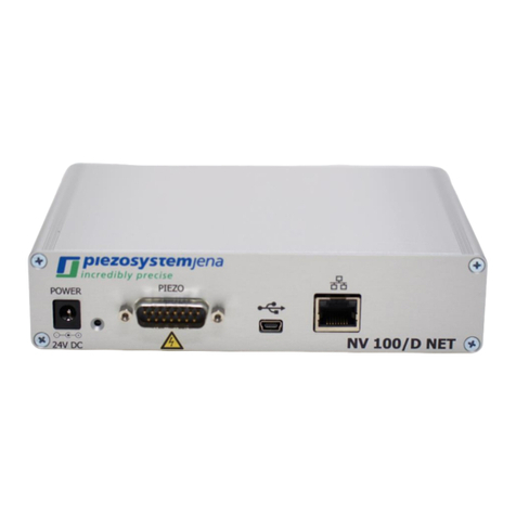
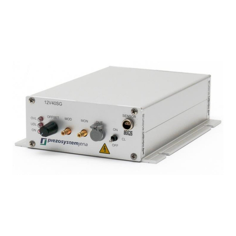
Other piezosystemjena Amplifier manuals

piezosystemjena
piezosystemjena series 30DV User manual

piezosystemjena
piezosystemjena NV100/D NET User manual

piezosystemjena
piezosystemjena 24DV40 User manual

piezosystemjena
piezosystemjena RCV 1000/3 User manual

piezosystemjena
piezosystemjena nano box USB User manual

piezosystemjena
piezosystemjena ENT User manual

piezosystemjena
piezosystemjena NV200/D NET User manual

piezosystemjena
piezosystemjena NV200/D NET User manual

piezosystemjena
piezosystemjena NV40/1CLE User manual

piezosystemjena
piezosystemjena 12V40 Series User manual