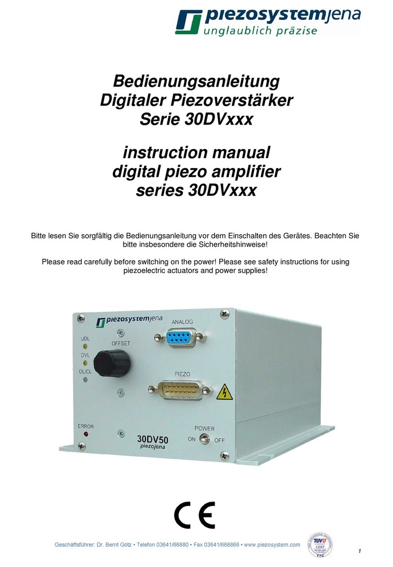
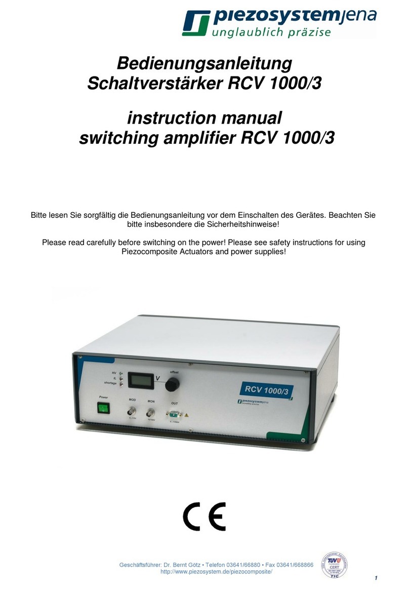
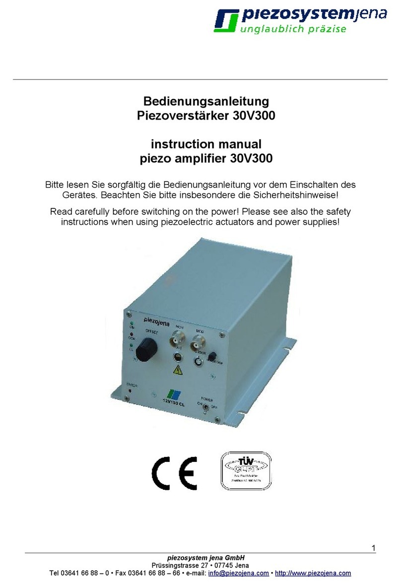
piezosystemjena NV200/D NET User manual

1 CEO: Dr. Bernt Götz • Phone +493641/66880 • Fax +493641/668866 • www.piezosystem.com
Preliminary
Instruction Manual
Digital Piezo Amplifier
NV200/D NET
Please read carefully before switching on the power! Please see safety instructions for
using piezoelectric actuators and power supplies!
28.10.2021
Draft of Rev 0

2 CEO: Dr. Bernt Götz • Phone +493641/66880 • Fax +493641/668866 • www.piezosystem.com
Table of contents
1Introduction...................................................................................................................................3
2Certification of piezosystem jena...................................................................................................3
3Declaration of conformity ..............................................................................................................3
4Purchased part package...............................................................................................................4
5Instructions for using piezo electrical elements and power supplies..............................................4
6Safety instructions.........................................................................................................................5
6.1 Icons......................................................................................................................................5
6.2 Installation & power supply ....................................................................................................6
6.3 Operation...............................................................................................................................6
6.4 Maintenance and inspection ..................................................................................................7
6.5 Environmental conditions.......................................................................................................7
7Instructions for checking the function of the system / quick start...................................................7
8How to operate the digital amplifier NV200/D NET........................................................................8
8.1 Introduction............................................................................................................................8
8.2 Technical data .......................................................................................................................9
8.3 Connectors and Pin Assignment..........................................................................................10
8.4 Establishing communication.................................................................................................13
8.5 Command list.......................................................................................................................17
8.6 Error messages ...................................................................................................................21
8.7 Status register......................................................................................................................22
8.8 Feedback control modes......................................................................................................23
8.9 Arbitrary waveform generator...............................................................................................25
8.10 Data recorder.......................................................................................................................26
8.11 Trigger.................................................................................................................................26
8.12 Temperature measurement..................................................................................................27
9Troubleshooting..........................................................................................................................28
10 Your notes...............................................................................................................................29

3 CEO: Dr. Bernt Götz • Phone +493641/66880 • Fax +493641/668866 • www.piezosystem.com
1 Introduction
This manual describes the digital piezo amplifier series NV200/D NET from piezosystem jena. You will
also find additional information regarding piezoelectric products.
Definition: All systems from piezosystem jena such as electronics, actuators, and optical systems are
called “units”.
If you have any problems, please contact the manufacturer of the system: piezosystem jena,
Stockholmer Str. 12, 07747 Jena. Phone: +49 36 41 66 88-0
2 Certification of piezosystem jena
The company piezosystem jena GmbH has worked according to a DIN EN ISO 9001 certified quality
management system since 1999. Its effectiveness is verified and proven by periodic audits by the TÜV.
3 Declaration of conformity
The CE Declaration of Conformity is available on our website www.piezosystem.com.
This instruction manual includes important information for using piezo actuators and
electronics. Please take the time to read this information. Piezo positioning systems
are mechanical systems that offer the highest precision. Correct handling guarantees
that this precision will be maintained over a long period of time.

4 CEO: Dr. Bernt Götz • Phone +493641/66880 • Fax +493641/668866 • www.piezosystem.com
4 Purchased part package
Please check the completeness of the delivery after receiving the shipment:
•piezo amplifier NV200/D NET
•wide range power supply 24 VDC
•USB cable
•instruction manual
For optional needed drivers or available software see our homepage.
5 Instructions for using piezo electrical elements and power supplies
•Piezoelectric actuators from piezosystem jena are controlled by voltages up to 180 V. These
values can be quite hazardous. Therefore, read the installation instructions carefully and ensure
that only authorized personnel handle the power supply.
•After transportation, piezoelectric actuators should be allowed to adapt to room temperature for
approximately 2 hours before being switched on.
•Piezoelectric actuators are made from ceramic materials with and without metallic casings. The
piezo-ceramic is a relatively brittle material. This should be noted when handling piezoelectric
actuators. All piezo elements are sensitive to bending or shock forces.
•Due to the piezoelectric effect, piezo actuators can generate electrical charges by changing the
mechanical load or the temperature, or by actions such as the ones described above.
•Piezoelectric actuators are able to work under high compressive forces. Only actuators with a
pre-load can be used under tensile loads (these tensile forces must be less than the pre-load
given in the data sheet). Please note that acceleration of the ceramic material (e.g., caused by
fall down, discharging, or high dynamic application) will occur.
•After excitation of the actuators by a voltage in the upper control range, the ceramic will move
and generate an opposite high voltage after disconnection.
•Heating of the ceramic material will occur during dynamic operation and is caused by structure
conditional loss processes. This may cause failure if the temperature exceeds specified values
cited below. With increasing temperature up to the Curie temperature TC, (usual values approx.
140 °C –250 °C) the piezoelectric effect disappears. We recommend working in temperatures
up to TC/2 (normally up to 80 °C).
•Piezoelectric actuators, such as stacks or other devices, work electrically as a capacitor. These
elements are able to store electrical energy over a long period of time (up to some days) and
the stored energy may be dangerous.
•If the actuator remains connected to the drive electronics, it will be unloaded within a second
after shutdown and quickly reaches harmless voltage values.
•Piezo actuators can only generate voltages by warming or cooling (caused by the longitudinal
change). The discharge potential should not be ignored due to the inner capacitance. This effect
is insignificant at usual room temperature.
•Piezo actuators from piezosystem jena are adjusted and glued. Any opening of the unit will
cause misalignment or possible malfunction and will result in the loss of the guarantee.
•Please only use original parts from piezosystem jena.
Please contact piezosystem jena or your local representative if there are any problems with your
actuator or power supply.
Caution! Shock forces may damage the built-in ceramic elements. Please avoid such forces, and
handle the units with care, otherwise the guarantee will be lost.
5 CEO: Dr. Bernt Götz • Phone +493641/66880 • Fax +493641/668866 • www.piezosystem.com
6 Safety instructions
6.1 Icons
RISK OF ELECTRIC SHOCK! Indicates that a risk of electric shock is present and the associated
warning should be observed.
CAUTION! REFER TO OPERATOR´S MANUAL –Refer to your operator’s manual for additional
information, such as important operating and maintenance instructions.
RISK OF ELECTRIC SHOCK!
•Do not open the units! There are no user serviceable parts inside and opening or removing
covers may expose you to dangerous shock hazards or other risks. Refer all servicing to
qualified service personnel.
•Do not spill any liquids into the cabinet or use the units near water.
CAUTION!
•Allow adequate ventilation around the units so that heat can properly dissipate. Do not block
ventilated openings or place the units near a radiator, oven, or other heat sources. Do not put
anything on top of the units except those that are designed for that purpose (e.g. actuators).
•Only work with the units in a clean and dry environment! Only specially prepared units (e.g.
actuators) can work under other conditions!
•Please only use original parts from piezosystem jena. piezosystem jena does not give any
warranty for damages or malfunction caused by additional parts not supplied by piezosystem
jena. Additional cables or connectors will change the calibration and other specified data. This
can change the specified properties of the units and cause them to malfunction.
•Piezo elements are sensitive systems capable of the highest positioning accuracy. They will
demonstrate their excellent properties only if they are handled correctly! Please mount them
properly at the special mounting points.
Immediately unplug your unit from the wall outlet and refer servicing to qualified service personnel under
the following conditions:
•when the cords or plugs are damaged
•if liquid has been spilled or objects have fallen into the unit
•if the unit has been exposed to rain or water
•if the unit has been dropped or the housing is damaged

6 CEO: Dr. Bernt Götz • Phone +493641/66880 • Fax +493641/668866 • www.piezosystem.com
6.2 Installation & power supply
RISK OF ELECTRIC SHOCK!
•Do not insert or unplug the power plug with wet hands, as this may result in electrical shock.
•Do not install in rooms where inflammable substances are stored. If flammable substances
come into contact with electrical parts inside, it could result in fire or electrical shock.
•Do not damage or modify the power cord. Also, do not place heavy objects on the power cord,
or pull on or excessively bend it, as this could cause electrical damage and result in a fire or
electrical shock.
•Always grasp the plug portion when unplugging the power cord. Pulling on the power cord may
expose or snap the core wire, or otherwise damage the power cord. If the cord is damaged, this
could cause an electricity leak and result in a fire or electrical shock.
CAUTION!
•Do not use accessories other than the ones provided (e.g. power cord). Only plug the power
cord into grounded power equipment and sockets.
•Do not place heavy objects on any cables (e.g. power cords, sensor cables, actuator cables,
optical cables).
•Do not block ventilated openings or place the units near a radiator, oven, or other heat sources.
•Plug in the power cord completely so that it cannot loosen inadvertently.
•Leave sufficient space around the power plug so that it can be unplugged easily. If objects are
placed around the power plug, you will be unable to unplug it in an emergency.
•Install the system so that the on/off-switch is easily accessible at all times.
•The power plug is the cut-off point to the main power supply.
6.3 Operation
RISK OF ELECTRIC SHOCK!
•Do not open the units! There are no user serviceable parts inside and opening or removing
covers may expose you to dangerous shock hazards or other risks. Refer all servicing to
qualified service personnel.
•Do not spill inflammable substances inside the voltage amplifier. If these items come into contact
with an electrical component inside the voltage amplifier, this may result in a fire or electrical
shock.
CAUTION!
•If the voltage amplifier emitssmoke, high heat, orunusual smells, immediately turn off the power
switch and unplug the power plug from the outlet. Then contact our technical service.

7 CEO: Dr. Bernt Götz • Phone +493641/66880 • Fax +493641/668866 • www.piezosystem.com
6.4 Maintenance and inspection
CAUTION!
•Before cleaning the exterior box of the voltage amplifier, turn off the power switch and unplug
the power plug. Failure to do so may result in a fire or electrical shock.
•Clean the exterior box using a damp cloth that has been firmly wrung-out. Do not use alcohols,
benzene, paint thinner or other inflammable substances. If flammable substances come into
contact with an electrical component inside the voltage amplifier, this may result in a fire or
electrical shock.
6.5 Environmental conditions
The amplifier can be used:
•indoors only
•at an altitude of up to 2000 m
•at a temperature between: 5 ... 35 °C
•at a relative humidity between: 5 ... 95 % (non-condensing)
The recommended environmental conditions:
•indoors only
•at an altitude of up to 2000 m
•at a temperature between: 20 ... 22 °C
•at a relative humidity between: 5 ... 80 % (non-condensing)
7 Instructions for checking the function of the system / quick start
When you open the package, please check to make sure all the necessary parts are included (see
packing list) and nothing is damaged. Check the electronics and the actuator for any visible damage:
•The top and bottom plates of the actuator (if it does not have another shape) should be parallel
each to each other and not have any scratches.
•If there is any damage to the system, please contact our local representative immediately!
•If the packaging material is damaged, please confirm this with the shipping company.
•Connect the piezo actuator by using the D-SUB 15pin connector. Be sure the cables are
connected properly to the electronics.
•Connect the device to PC with an USB cable.
•Connect the power supply (24 VDC)
•Normally, the PC installs necessary drivers automatically
•After initialization, the LED lights green (open loop mode) or orange (closed loop mode)
•In case of irregularities, please read the chapter on troubleshooting.
•The function check is complete.

8 CEO: Dr. Bernt Götz • Phone +493641/66880 • Fax +493641/668866 • www.piezosystem.com
8 How to operate the digital amplifier NV200/D NET
8.1 Introduction
The digital amplifier NV200/D NET is designed to control the D-actuators from piezosystem jena. it can
be used with actuators with or without integrated position sensor. Actuators with integrated position
sensor allows positioning without creeping or hysteresis by digital PID loop control. The amplifier can
be controlled by USB, Ethernet, SPI or analog voltage input and reaches a resolution of 16 bits.
piezosystem jena supports driver for Windows® operating systems.
The integrated digital loop controller comes as PID controller, additionally a slew rate limiter, a low pass
filter of 4th order for set point filtering and a notch filter are available.
The digital amplifier NV200/D NET allows the interchangeability from D-actuators and amplifier. All
needed information is stored on the ID-chip, located in actuator’s connector, and will be read
automatically by the piezo controller after system start.
The actuator is connected to the NV200/D NET using the “PIEZO” plug. After switch on, the device runs
a self-test procedure, while the indicator LED is lightning red. This takes about 3 s. During this step the
controller reads the system specific parameters from the actuators ID-chip and sets up the controller. If
no actuator is connected, the LED stays red.
After the self-test, the actuator moves to its initial position. In case of open loop mode to the desired
voltage, in case of closed loop mode it moves to the set position.
In OL mode, the actuator is directly controlled by a voltage between -20V and +180V, however it will
be automatically limited to theadmissible voltage range of the connected actuator. The reachable stroke
(pos. 1 to pos. 4) in unloaded condition can be seen on the actuator’s calibration protocol. The stroke
vs. voltage relationship is non-linear, shows hysteresis and creep and is affected by the actuators load
condition. The stroke decreases by higher stiffness loads. To reach a defined position, actuators with
integrated position sensors are used. They will have a smaller stroke in CL mode, the remaining stroke,
compared to OL mode is used as a reserve to reach the end positions (pos. 2 and pos. 3) also under
load.

9 CEO: Dr. Bernt Götz • Phone +493641/66880 • Fax +493641/668866 • www.piezosystem.com
8.2 Technical data
Input voltage
24VDC
Power supply connector
low voltage socket with 2.1mm pin
Input current
max. 2A (rms) / 7A (peak) @ 24V, idle current 110mA
Power consumption
max. 48W
Output voltages
-10 V... +180V or -20V … +130V
(automatically adapted to the actuator)
Output current
200mA (continuous)
400mA (peak for 1.2ms)
NanoX®-mode:
2 x 100 mA (continuous)
2 x 200 mA (peak for 1.2ms)
Output voltage noise
0.7mVRMS @ 500Hz bandwidth
Actuator / measurement
connector „PIEZO“:
15 pin D-Sub plug
Safety functions:
short circuit proof, over temperature protection
Display (LED):
green / orange / red
Interfaces
USB, Ethernet
Interface connectors
USB-C, RJ45
Cooling
passive
Dimensions (L * W * H):
165 x 120 x 65 mm³
Weight:
0.5kg

10 CEO: Dr. Bernt Götz • Phone +493641/66880 • Fax +493641/668866 • www.piezosystem.com
8.3 Connectors and Pin Assignment
8.3.1 Overview
I/O
connector
Ethernet
connector
USB
connector
Piezo actuator
connector
connector
Status
LED
Power supply
connector

11 CEO: Dr. Bernt Götz • Phone +493641/66880 • Fax +493641/668866 • www.piezosystem.com
8.3.2 Piezo actuator connector
Type: 15 pin D-SUB plug
Pin
Label
Description
1, 2, 11
AGND
Analog ground
3
+15V*
Operating voltage measurement +15V
4, 14
GND
Digital ground
5
SDA
I²C-Bus SDA
6
3.3Veeprom*
Supply voltage ID-Chip
7
Vout2
Second voltage for NanoX® actuator +180 V … -20V
8
Vout
Actuator voltage -20 V... +180V
9
+MEAS
Position signal -8 V... +8V
10
-15V*
Supply voltage measurement -15V
12
SCL
I²C-Bus SCL
13
DETECT
Actuator detection
15
Piezo ground
Actuator ground
[*] Not for external use
The actuator is connected to this plug. The actuator voltage goes to the piezo, the position signal from
the measurement system goes to the DSP, and the integrated actuator information is stored on an ID-
chip which goes to the main controller. It is important that the locking screws are screwed into the front
panel. The dangerous voltages will be switched on only after connecting the actuator. When
disconnecting the actuator, the dangerous voltages will be switched off by a safety relay.

12 CEO: Dr. Bernt Götz • Phone +493641/66880 • Fax +493641/668866 • www.piezosystem.com
8.3.3 I/O connector
Type: 15 pin D-Sub HD jack
Pin
Label
Description
1
MOD
Analog modulation input (0...10V), (Impedance 1 MΩ)
2
MON2
Not used
3
TRG in
Trigger input (TTL, 0 / 3,3V…5V)
4
SPI: CLK
SPI clock (3,3V logic, slave input)
5
DGND
Digital ground (for SPI & Trigger)
6
AGND
Analog ground (for MOD & MON)
7
DGND
Digital ground (for SPI & Trigger)
8
DGND
Digital ground (for SPI & Trigger)
9
SPI: MOSI
MOSI (3,3V logic, slave input)
10
TxD
Not used
11
MON
Analog monitor output (0 ...10V)
12
TRG out
Trigger output (TTL 3,3V)
13
SPI: /CS
Chip select (3,3V logic, low active, slave input)
14
SPI: MISO
MISO (3,3V logic, slave output)
15
RxD
Not used
shield wire
AGND
Analog ground
8.3.4 USB connector
The USB-C type connector supports USB 2.0 and allows the device to be controlled via a serial COM-
Port.
8.3.5 Ethernet connector
The RJ45 Ethernet connector allows the device to be controlled via a Telnet connection.
8.3.6 Power supply connector
The power supply connector is a low voltage socket with a 2.1mm pin. The supply voltage range is

13 CEO: Dr. Bernt Götz • Phone +493641/66880 • Fax +493641/668866 • www.piezosystem.com
8.4 Establishing communication
8.4.1 Serial communication via USB
The NV200/D NET can easily communicate with your PC with the use of a terminal program such as
HTerm. A USB connection cable (included) is required to connect to your computer. The properties of
the COM port are: 115200baud, 8bit, no parity, 1 stop bit, software handshake (XON / XOFF).
When the device is powered and connected, it answers after receiving “CR - carriage return” (Enter
Key) with its prompt “NV200/D NET>”
8.4.2 Telnet communication via Ethernet
The communication with the NV200/D NET over ethernet can be done with the Windows Telnet client.
If not already enabled, this can be done via the “Turn Windows features on or off” functionality.

14 CEO: Dr. Bernt Götz • Phone +493641/66880 • Fax +493641/668866 • www.piezosystem.com
Alternatively, you can use other programs like Putty. After successful connection the full command set
is available.
The Telnet connection can be established via the IP address of the controller and the correct port
number. The default port number is 23.
By default, the IP address is set dynamically over DHCP. If necessary, it can be set static over the
configuration. To get the IP address of the device ask you network administrator or use our tool „IP-
Search“ from the website.
It is possible to use the host name of the device, if the „DHCP FQDN option“ is enabled. By default, the
host name is „C“ + the last 6 digits of the MAC address. (Example: MAC=00:80:A3:E5:74:74 →host
name: „CE57474“). The MAC address can be found on the type plate of the device.

15 CEO: Dr. Bernt Götz • Phone +493641/66880 • Fax +493641/668866 • www.piezosystem.com
8.4.3 Ethernet configuration
The network settings can be changed via Telnet connection (port: 9999) or via a web browser.
It is possible to change the IP address and the default port (23) for Telnet communication with the
device. Under the item „Server“ the IP address can be set to a static one or to DHCP. Under item
„Channel 1“ the port can be changed.
By accessing the IP in a web browser, the settings can be accessed graphically.
CAUTION: By default, the IP address is retrieved over DHCP. In networks without a DHCP server there
is no access via Telnet possible without setting a static IP address.

16 CEO: Dr. Bernt Götz • Phone +493641/66880 • Fax +493641/668866 • www.piezosystem.com
8.4.4 SPI communication
Real-time communication can take place via the SPI interface. The device works as an SPI slave, i.e.
the device receives setpoints from an external SPI master. The return value retrieved over the MISO
channel can be set to different quantities (e.g. position values) via the USB or Ethernet interfaces. The
SPI connection is exclusively to send setpoints to the device. The device has to be configured via the
USB or Ethernet interfaces.
The interface requires the following configuration:
•3.3 V logic voltage
•SPI clock: max. 6 MHz
•SPI mode: 3 (CPOL = 1, CPHA = 1)
•SPI CS: low active
•Word length: 16 bit, MSB First
Value range of the SPI-setpoint:
•in closed loop mode [0x0000 … 0xFFFE] corresponds to 0 … 100% of the closed loop travel of
the connected actuator
•in open loop mode [0x0000 … 0xFFFE] corresponds to 0 … 100% of the admissible piezo
voltage of the connected actuator
•The value [0xFFFF] is used for error detection and is not interpreted as a setpoint
Value range of the return value:
•The value selected by spisrc command is scaled to [0x0000 … 0xFFFF]
To synchronize the NV200D/NET PID controller loop execution to the SPI master the spitrg option can
be used. In mode spitrg,0 the internal 20 kHz clock is used to trigger the digital control loop interrupt.
In mode spitrg,1 the digital control loop interrupt is executed only when a new SPI setpoint is received.
This allows precise synchronization of several NV200D/NET controllers. However, it is very important
to make sure that SPI commands are sent with a 20 kHz update rate in order to get the right timing for
the digital filters, since they are parameterized with respect to a constant sampling rate of 20 kHz.

17 CEO: Dr. Bernt Götz • Phone +493641/66880 • Fax +493641/668866 • www.piezosystem.com
8.5 Command list
All commands with one parameter to send are used in the following scheme:
<command>,<value>\r
Commands with indexing are used like this:
<command>,<index>,<value>\r
In case of read-only commands, commands without a value or to read back a value, the command is
issued without a value:
<command>\r
Command
Description
Value range
General Commands
s
This command list
Read-only
reset
Hardware-reset of the controller
-
fenable
During controller power-up, cycle through the
entire piezo voltage range once
0= disabled
1= enabled
sinit
Initial actuator position after power-up
0 …100 %
set
Setpoint as position or voltage
In open loop: voltage in V
In closed loop: position in µm or µrad
Range is limited by the actuators
stroke and voltage range
meas
For actuators with sensor: Position in actuator
units (µm or mrad)
For actuators without sensor: Piezo voltage in V
Read-only
imeas
Measured piezo current
0 = piezo current 1
1 = piezo current 2
temp
Heat sink temperature
Read-only
stat
Status register, see section 8.6 for details
Read-only
posmin
Lower motion range limit
Read-only
posmax
Upper motion range limit
Read-only
avmin
Lower voltage range limit
Read-only
avmax
Upper voltage range limit
Read-only
modsrc
Signal source for setpoint
0 = set-Command via USB or
Ethernet
1 = Anlaog In
2 = SPI
3 = Arbitrary waveform generator
modon
Switch on Analog In
0 = switched off
1 = switched on
monsrc
Source of data for analog output
0 = position (closed loop)
1 = setpoint
2 = piezo voltage (controller output)
3 = position error
4 = abs(position error)
5 = position (open loop)
6 = piezo current 1
7 = piezo current 2

18 CEO: Dr. Bernt Götz • Phone +493641/66880 • Fax +493641/668866 • www.piezosystem.com
PID and filters
cl
PID open loop or closed loop mode
0 = open loop
1 = closed loop
sr
Slew rate limit
0.0000008 ... 2000.0
(2000 =
disabled)
kp
PID controller proportional term amplification
0 ... 10000 (0 = disabled)
ki
PID controller integral term amplification
0 ... 10000 (0 = disabled)
kd
PID controller differential term amplification
0 ... 10000 (0 = disabled)
pcf
PID controllers feed forward control amplification
0 … 1 (0 = disabled)
lpon
Enable or disable setpoint lowpass filter
0 = off
1 = on
lpf
Setpoint low pass filter cut-off frequency
1 ... 10000 Hz
notchon
Enable or disable notch filter
0 = off
1 = on
notchf
Notch filter frequency
0 … 20000 Hz
notchb
Notch filter -3dB bandwidth
0 … 20000 Hz (max. 2 * notchf)
poslpf
Measured position low pass filter cut-off
frequency
poslpon
Enable or disable measured position low pass
filter
0 = off
1 = on
Arbitrary waveform generator
grun
Start or stop the arbitrary waveform generator
0 = stop
1 = start
gsarb
Start index for arbitrary waveform generator
output
0…1023
gearb
End index for arbitrary waveform generator
output
0…1023
gcarb
Number of cycles to run
0 = infinitely
1…65535
goarb
Offset index when arbitrary waveform generator
gets started
0…1023
giarb
Current index (e.g. after a stop command)
Read-only
gtarb
Output sampling time (<value> * 50µs)
0…65535
gbarb
Output values in the buffer in relative units
index: 0…1023
value: 0.0…100.0 (%)
gparb
Output values in the buffer in length units (µm or
mrad)
index: 0…1023
value: posmin … posmax
gsave
Save the buffer in the EEPROM (End of process
is acknowledged by CR LF)
-
gload
Loading the buffer from the EEPROM (End of
process is acknowledged by CR LF)
-
Data recorder
recsrc
Source of data to be stored in data recorder
channel
recsrc,<ch>,<src>
ch:
0 = buffer A
1 = buffer B
src:
0 = piezo position (closed loop)
1 = setpoint
2 = piezo voltage (controller output)
3 = position error
4 = abs(position error)
5 = piezo position (open loop)
6 = piezo current 1
7 = piezo current 2
recast
Autostart condition of the data recorder
0 = off
1 = start on
set
-command

19 CEO: Dr. Bernt Götz • Phone +493641/66880 • Fax +493641/668866 • www.piezosystem.com
2 = start on
grun
-command
recstr
Data recorder stride (store only every nth value)
0….65535
reclen
Memory length for each of the two data recorder
channels
0 …. 6144
0 = infinite loop over maximum length
until recorder is stopped manually
recrun
Start or stop the data recorder
0 = stop
1 = start
recout
Read out the data recorder line by line:
• ch: channel
• Index: Distance to index 0
• Length: number of values (max. to reclen or
rec_max)
Response:
recout, <ch>, <index>,<value>
ch:
0 = channel A
1 = channel B
Index:
0… 6143
Length:
1… 6144
recoutf
Read out the complete data recorder comma-
seperated:
Response:
recoutf, <ch>, <value 1>,<value 2>,….,<value
reclen>
ch:
0 = channel A
1 = channel B
Trigger In
trgfkt
Function to run on trigger input
0 = none
1 = waveform generator start
2 = waveform generator step
3 = waveform generator sync
4 = ILC sync
5 = start data recorder
Trigger Out
trgedg
Trigger on falling and/or rising edge
0 = off
1 = falling, not inverted
2 = rising, not inverted
3 = both, not inverted
trgsrc
Signal source for trigger out
0 = position
1 = setpoint
trgss
Trigger output start (lower position)
(
posmin
+0.001)...(
posmax
-0.001)
trgse
Trigger output stop (upper position)
(
posmin
+0.001)...(
posmax
-0.001)
trgsi
Trigger output step size
0.001…(
posmax
-0.001)
trglen
Trigger length in samples t=50µs*trglen
(trglen=0→t=1µs)
0…255
SPI
spisrc
SPI monitor/ Return value via MISO
0 = 0x0000
1 = position (closed loop)
2 = setpoint
3 = piezo voltage (controller output) 4
= position error
5 = abs(position error)
6 = position (open loop)
7 = piezo current 1
8 = piezo current 2
9 = test value (0x5A5A)
spitrg
Set the PID control loop interrupt source
0 = internal
1 = SPI
mspi
Gain return value
0.0…1.0
(Default: 1.0)
nspi
Offset return value
-65535.0…65535.0
(Default: 0.0)
spih
Current SPI setpoint in hex
Only query possible

20 CEO: Dr. Bernt Götz • Phone +493641/66880 • Fax +493641/668866 • www.piezosystem.com
spis
Current SPI setpoint
Only query possible
ILC control
imode
ILC controller operating status
0 = PID controll (ILC off)
1 = identification mode
2 = feedforward control mode
3 = feedback control mode
ipara
ILC parameter query
-
iemin
Lower learning limit “emin”
0.0001 … 1.000 (default: 0.1)
irho
Learning rate “rho”
0.0001 … 1.000 (default: 0.1)
in0
Number of basic scanning
n0 >= n1
2…65535
in1
Number of subsamples
n1 < 1024 (=N1_max)
n1 = 2k
2,4,8,16,32,64,…1024
inx
Number of frequency components to be learned
nx < 128 (=NX_max)
nx < ½ * n1
1…128
iut
Query of the manipulated value curve in the time
domain
Without index = output as array (up to
in1)
With index (up to in1) = output of the
index
iyt
Query the measured value in the time domain
Without index = output as array (up to
in1)
With index (up to in1) = output of the
index
ii1t
Query the Current value 1 in the time domain
Without index = output as array (up to
in1)
With index (up to in1) = output of the
index
ii2t
Query the Current value 2 in the time domain
Without index = output as array (up to
in1)
With index (up to in1) = output of the
index
igc
Query of the correction curve in the frequency
domain
Without index = output as array (up to
inx)
With index (up to inx) = output of the
index
iuc
Query of the manipulated variable curve in the
frequency range
Without index = output as array (up to
inx)
With index (up to inx) = output of the
index
iwc
Query and set the setpoint curve in the frequency
domain
Set:
<Index> = 0… inx
<value> = - infinite ... + infinite
Interrogate:
Without index = output as an array
(up to inx)
With index (up to inx) = output of the
index
iyc
Queries measured value curve in the frequency
domain
Without index = output as array (up to
inx)
With index (up to inx) = output of the
index
isave
Save curves in the actuator (Number = nx)
-
iload
Load curves from the actuator (Number = nx)
-
iclr
clear memory
-
Table of contents
Other piezosystemjena Amplifier manuals

piezosystemjena
piezosystemjena NV100/D NET User manual

piezosystemjena
piezosystemjena NV40/1CLE User manual

piezosystemjena
piezosystemjena 12V40 Series User manual

piezosystemjena
piezosystemjena NV40/3 User manual

piezosystemjena
piezosystemjena NV200/D NET User manual

piezosystemjena
piezosystemjena RCV 1000/3 User manual

piezosystemjena
piezosystemjena series 30DV User manual

piezosystemjena
piezosystemjena ENT User manual

piezosystemjena
piezosystemjena 30V300 User manual

piezosystemjena
piezosystemjena nano box USB User manual