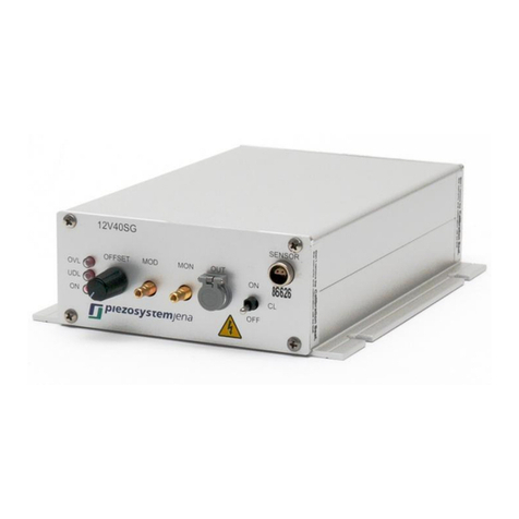
piezosystemjena NV40/1CLE User manual

Telefon: +49 (3641) 66880 • Fax: +49 (3641) 668866 • info@piezojena.com • http://www.piezojena.com
instruction manual
voltage amplifier NV40/1CLE
Read carefully before switching on the power! Please see also instructions for
safety, using piezoelectric actuators and power supplies!
230V / 50Hz Art.Nr. E-101-73
115V / 60Hz Art.Nr. E-101-74
95 V / 60 Hz Art.Nr. E-101-75

Telefon: +49 (3641) 66880 • Fax: +49 (3641) 668866 • info@piezojena.com • http://www.piezojena.com
1
Instruction manual pages 1 ... 20
(english)
english version: last change 2018-11-01 by TM

Telefon: +49 (3641) 66880 • Fax: +49 (3641) 668866 • info@piezojena.com • http://www.piezojena.com
2

Telefon: +49 (3641) 66880 • Fax: +49 (3641) 668866 • info@piezojena.com • http://www.piezojena.com
3
table of content
1. introduction ............................................................................................... 4
2. certification of piezosystem jena ................................................................. 4
3. declaration of conformity ............................................................................ 5
4. purchased part package............................................................................. 6
5. instructions for using piezoelectrical elements and power supplies .............. 6
6. safety instructions ...................................................................................... 7
6.1. installation, power supply ........................................................................... 8
6.2. operation ................................................................................................... 9
6.3. maintenance and inspection ..................................................................... 10
6.4. environmental conditions ......................................................................... 10
7. instructions for checking the function of the system / quick start ................ 10
8. interface setup ......................................................................................... 12
9. how to operate the NV40/1CLE ................................................................ 12
9.1. common introduction ............................................................................... 12
9.2. technical data .......................................................................................... 13
9.3. initiation................................................................................................... 14
9.4. service .................................................................................................... 14
9.4.1. button “Closed Loop” ............................................................................... 15
9.4.2. button “MEM” .......................................................................................... 15
9.5. display .................................................................................................... 16
9.6. modulation input: MOD ............................................................................ 16
9.7. monitor output: MON ............................................................................... 16
9.8. actuator connection: OUT ........................................................................ 16
9.9. measuring system connection: SENSOR .................................................. 17
9.10. RS232 interface ....................................................................................... 17
9.10.1. write-command wr ................................................................................... 17
9.10.2. read-command rd .................................................................................... 18
9.10.3. remote control command i0, i1 ................................................................. 18
9.10.4. operation mode command ol, cl................................................................ 18
9.10.5. error reports ............................................................................................ 18
10. possibilities of the error correction ............................................................ 19
11. your notes ............................................................................................... 20
Telefon: +49 (3641) 66880 • Fax: +49 (3641) 668866 • info@piezojena.com • http://www.piezojena.com
4
1. introduction
This manual describes the piezo amplifier NV40/1CLE from piezosystem jena. You will
also find additional information regarding piezoelectric products.
definition: All systems from piezosystem jena such as electronics, actuators and optical
systems are called units.
If you have any problems please contact the manufacturer of the system: piezosystem
jena, Pruessingstrasse 27, 07745 Jena. phone: +49 36 41 66 88-0
2. certification of piezosystem jena
The company piezosystem jena GmbH has been certified by DIN EN ISO 9001 since
1999. More information about our certifications can be found at
https://www.piezosystem.com/downloads/certifications/.

Telefon: +49 (3641) 66880 • Fax: +49 (3641) 668866 • info@piezojena.com • http://www.piezojena.com
5
3. declaration of conformity

Telefon: +49 (3641) 66880 • Fax: +49 (3641) 668866 • info@piezojena.com • http://www.piezojena.com
6
4. purchased part package
Please check the completeness of the delivery after receiving the shipment:
• voltage amplifier NV40/1CLE
• power cord
• RS232 cord
• instruction manual
• CD-ROM with driver, software and instruction manual
5. instructions for using piezoelectrical elements and power supplies
• Piezoelectric actuators from piezosystem jena are controlled by voltages up to
150V. These values can be quite hazardous. Therefore, read the installation
instructions carefully and only authorized personal should handle the power supply.
• After transportation, piezoelectric actuators should be allowed to adapt for
approximately 2 hours to the room temperature before being switched on.
• Piezoelectric actuators are made from ceramic materials with and without metallic
casings. The piezo-ceramic is a relatively brittle material. This should be noted
when handling piezoelectrical actuators. All piezo-elements are sensitive to
bending or shock forces.
• Due to the piezoelectric effect piezo-actuators can generate electrical charges by
changing the mechanical load or the temperature or such actions described above.
• Piezoelectric actuators are able to work under high compressive forces, only
actuators with pre-load can be used under tensile loads (these tensile forces must
be less then the pre-load, given in the data sheet).
• Please note that the acceleration of the ceramic material (e.g., caused by fall down,
discharging or high dynamic application) will occur.
• After excitation of the actuators by a voltage in the upper control range, the ceramic
will move and generate an opposite high voltage after disconnection.
• Heating of the ceramic material will occur during dynamic operation and is caused
by structure conditional loss processes. This may cause failure if the temperature
exceeds specified values cited below.
• With increasing temperature, up to the Curie temperature (usual values approx.
140°C - 250°C), the piezoelectric effect disappears.
• Piezoelectric actuators such stacks or various tables work electrically as a
capacitance. These elements are able to store electrical energy over a long period
(up to some days) and the stored energy may be dangerous.
• If the actuator remains connected to the drive electronics, it is unloaded within a
second after shutdown and quickly reaches harmless voltage values.

Telefon: +49 (3641) 66880 • Fax: +49 (3641) 668866 • info@piezojena.com • http://www.piezojena.com
7
• Piezo-actuators can generate voltages by warming or cooling only (caused by the
longitudinal change). The discharge potential should not be ignored due to the inner
capacitance. This effect is insignificant at usual room temperature.
• Piezo-actuators from piezosystem jena are adjusted and glued. Any opening of
the unit will cause misalignment or possible malfunction and the guarantee will be
lost.
• Please use only original parts from piezosystem jena.
• Please contact piezosystem jena or your local representative, if there are any
problems with your actuator or power supply. The responsible representatives for
the countries you can find at our website: http://www.piezojena.com at the rubric
Representative.
Caution!
Shock forces may damage the built-in ceramic element. Please avoid such forces, and
handle the units with care, otherwise the guarantee will be lost.
6. safety instructions
Icons
• RISK OF ELECTRIC SHOCK! Indicates that a risk of electric shock is present
and the associated warning should be observed.
CAUTION! REFER TO OPERATOR´S MANUAL – Refer to your operator`s
manual for additional information, such as important operating and
maintenance instructions.
RISK OF ELECTRIC SHOCK!
• Do not open the units! There are no user serviceable parts inside and opening or
removing covers may expose you to dangerous shock hazards or other risks. Refer
all servicing to qualified service personnel.
• Do not spill any liquids into the cabinet or use the units near water. This could cause
an electric shock, fire or malfunction of the unit.
• Do not touch the OUT-plug socket on the front panel. It could be under dangerous
voltage.
• Do not insert objects of any kind into the cabinet slots, as they may touch
dangerous voltage points, which can be harmful or fatal or may cause electric
shock, fire or equipment failure.

Telefon: +49 (3641) 66880 • Fax: +49 (3641) 668866 • info@piezojena.com • http://www.piezojena.com
8
CAUTION!
• Allow adequate ventilation around the units so that heat can properly dissipate. Do
not block ventilated openings or place the units near a radiator, oven or other heat
sources. Do not put anything on top of the units except those that are designed for
that purpose (e.g. actuators).
• Work with the units only in a clean and dry environment! Only specially prepared
units (e.g. actuators) can work under other conditions!
• piezosystem jena does not give any warranty for damages or malfunction caused
by additional parts not supplied by piezosystem jena. Additional cables or
connectors will change the calibration and other specified data. This can change
the specified properties of the units and cause them to malfunction.
• Piezoelementes are sensitive systems capable of the highest positioning accuracy.
They will demonstrate their excellent properties only if they are handled correctly!
Please mount them properly only at the special mounting points.
• Do not place any heavy objects on any cables (e.g. power cords, sensor cables,
actuator cables, optical cables). Damage may cause malfunction or shock or fire!
• Do not place the units on a sloping or unstable cart, stand or table as they may fall
or not work accurately.
Immediately unplug your unit from the wall outlet and refer servicing to qualified service
personnel under the following conditions:
• when the power cord or plug is damaged
• if liquid has been spilled or objects have fallen into the unit
• if the unit has been exposed to rain or water
• if the unit has been dropped or the housing is damaged
6.1. installation, power supply
RISK OF ELECTRIC SHOCK
• Do not insert or unplug the power plug with wet hands, as this may result in
electrical shock.
• Do not install in rooms, where inflammable substances are stored. If flammable
substances come into contact with electrical parts inside, this may result in fire or
electrical shock.
• Do not damage or modify the power cord. Also, do not place heavy objects on the
power cord, or pull on or excessively bend it, as this could cause electrical damage
and result in a fire or electrical shock.
• Always grasp the plug portion when unplugging the power plug. Pulling on the
power cord may expose or snap the core wire, or otherwise damage the power

Telefon: +49 (3641) 66880 • Fax: +49 (3641) 668866 • info@piezojena.com • http://www.piezojena.com
9
cord. If the cord is damaged, this could cause an electricity leak and result in a fire
or electrical shock.
CAUTION!
• Do not use accessories other than the provided (e.g. power cord). Plug the power
cord only in grounding equipment conductor power sockets.
• Halten Sie die im Datenblatt angegebenen Betriebsspannungsgrenzen ein, da es
sonst zum Defekt des Gerätes kommen kann.
• Do not place any heavy objects on any cables (e.g. power cords, sensor cables,
actuator cables, optical cables).
• Do not block ventilated openings or place the units near a radiator, oven or other
heat sources. Do not put anything on top oft he units exept those that are designed
for that purposes (e.g. actuators).
• Plug the power cord completely in the grounding equipment conductor power
sockets so that it can not loosening inadvertently.
• Leave sufficient space around the power plug so that it can be unplugged easily. If
objects are placed around the power plug, you will be unable to unplug it in an
emergency.
• Install the system in that way, that the on/off-switch is accessible without problems.
6.2. operation
RISK OF ELECTRIC SHOCK!
• Do not open the units! There are no user serviceable parts inside and opening or
removing covers may expose you to dangerous shock hazards or other risks. Refer
all servicing to qualified service personnel.
• Do not spill inflammable substances inside the voltage amplifier. If these items
come into contact with an electrical component inside the voltage amplifier, this
may result in a fire or electrical shock.
CAUTION!
• If the voltage amplifier emits smoke, big heat or unusual smells, immediately turn
off the power switch and unplug the power plug from the outlet. Then contact our
technical service.

Telefon: +49 (3641) 66880 • Fax: +49 (3641) 668866 • info@piezojena.com • http://www.piezojena.com
10
6.3. maintenance and inspection
CAUTION!
• When cleaning the exterior box of the voltage amplifier, first turn off the power
switch and unplug the power plug. Failure to observe these items may result in a
fire or electrical shock.
• Cleaning the exterior box using a firmly wrung-out cloth. Do not use alcohol,
benzene, paint thinner or other inflammable substances. If flammable substances
come into contact with an electrical component inside the voltage amplifier, this
may result in a fire or electrical shock.
6.4. environmental conditions
The amplifier can be used:
• indoor
• altitude up to 2000 m
• temperature: 5 ... 35 °C
• relative humidity: 5 ... 95% (non-condensing)
The recommended environmental conditions are:
• indoor
• altitude up to 2000 m
• temperature: 20 ... 22 °C
• relative humidity: 5 ... 80% (non-condensing)
7. instructions for checking the function of the system / quick start
When you open the package, please check to make sure all the necessary parts are
complete (see packing list) and nothing is damaged.
Check the electronics and the actuator for any visible damage:
• The top and bottom plate of the actuator (if it does not have another shape) should
be parallel each to each other, without scratches.
• If there is any damage to the system please contact our local representative
immediately!
• If the packaging material is damaged please confirm this with the shipping
company.

Telefon: +49 (3641) 66880 • Fax: +49 (3641) 668866 • info@piezojena.com • http://www.piezojena.com
11
Before you switch on the system, please check:
• The main voltage supplied in your country is the same as installed for the system.
(Check the voltage label on the bottom side of the electronics and the datasheet
on point 9.2.)
• The potentiometer should be in maximum counter clockwise position (Pos. 0 or
Pos.1 depending on the operation mode)
• The power switch should be in the off position
• Connect the power cable.
• Connect the piezo-element by using the LEMO connector. Be sure the cables are
connected properly to the electronics.
• Switch the system on (power = on). If the light „CL ON“ is on, press the button
„Closed Loop“. The display shows the output voltage in open loop operation.
• Turn the potentiometer to the maximum clockwise position. The display shows the
maximum position. The actuator is now in position 4. (see diagram 1)
• Turn the
potentiometer to the maximum counter clockwise position (Pos. 1).
• Switch on the closed loop (push the button „Closed Loop“, „CL ON“ is illuminated).
The actuator moves to its zero position in closed loop mode
(Pos. 2), the displays shows 0.0µm if there is no offset to the system. Offset is
accomplished by the offset potentiometer or external offset (e.g. a load). Because
of the fast motion of the actuator to Pos. 2 a cracking noise can be heard. This is
normal and not a malfunction!
• Turn the potentiometer to the clockwise position again. The actuator makes its
maximum movement in closed loop mode (pos. 3). The total motion in closed loop
mode is pos. 3 - pos. 2. The specific value for that axis is given in the calibration
curve of the actuator (see the calibration protocol for your actuator).
• Turn the potentiometer to its counter clockwise zero position, switch off the closed
loop switch (push „Closed Loop“, „CL ON“ is off).
• If the procedure is done you can switch off the electronics.
• Before you switch off the electronics, be sure that the potentiometer is in the left
zero position and the closed loop switch is switched off!
Das Bild kann nicht angezeigt werden.
open loop
diagram 1: open loop – closed loop motion

Telefon: +49 (3641) 66880 • Fax: +49 (3641) 668866 • info@piezojena.com • http://www.piezojena.com
12
8. interface setup
• Connect the RS232 serial connectors of your IBM compatible computer and the
NV40/1CLE by using a standard interface line.
• Switch ON both units.
• The communication between voltage amplifier and computer can be achieved by
using any terminal program (normally it is part of your operation system, please
refer your OS documentation).
• RS232 parameters: COMx: 9600,n,8,1
• You will see an echo on your screen containing the firmware version.
9. how to operate the NV40/1CLE
9.1. common introduction
The voltage amplifier NV40/1CLE was especially developed for one channel positioning
tasks. The primary drive for developing the system was simple service and universal
usage of the unit.
Caution:
The voltage amplifier NV40/1CLE controls piezo elements with integrated measuring
system. In this case, all units, piezo actuator, measuring system and voltage amplifier
must be calibrated on each other. Calibration takes place before the delivery. In open
loop operating mode the output voltage will be displayed, in closed loop operation the
measured motion of the actuator will be displayed.
Please note: If power to the amplifier is lost, the system automatically reverts to the
previously chosen operation mode after power on.
Systems without measuring system:
If you purchased the voltage amplifier without an actuator and/or with an actuator without
measuring system, you can work with it in the non-controlled operation mode. In that
case, we will adjust the display to show the actuator voltage in volts (-10...+150V) instead
of the motion in microns.
In case of a subsequent adaptation of a measuring system, a calibration of the electronics
is necessary. To do so, actuator, electronics and measuring system must be returned to
piezosystem jena for calibration. There is an additional charge for special calibration.
Please contact your representative to determine if additional calibration is possible.

Telefon: +49 (3641) 66880 • Fax: +49 (3641) 668866 • info@piezojena.com • http://www.piezojena.com
13
technical data
article number
E-101-75
E-101-74
E-101-73
power supply
95V 60Hz
115V 60Hz
230V 50Hz
power supply range
85...115V
+-10%
+-10%
max. current
250mA
160mA
120mA
fuses
2x T315mA
250V
2x T250mA
250V
2x T200mA
250V
dimensions wxdxh [mm]
170 x 200 x 70
mass [kg]
1,6
number of channels
1
display
LED; 5 digits
power [W]
6
output current [mA]
40
output voltage (OUT)
-10 ... +150V (adjustable manual or by software)
output connector (OUT)
LEMO 0S.302
sensor connector
ODU series L, 4pin
modulation input (MOD)
0 ... +10V BNC
inner resistance
10kW
monitor voltage (MON)
0 ... +10V BNC
noise of the output
voltage
0.3mVRMS @ 500Hz
bandwidth [Hz]
350Hz (without connected actuator)
polarity
positive
table 1: technical data NV40/1CLE

Telefon: +49 (3641) 66880 • Fax: +49 (3641) 668866 • info@piezojena.com • http://www.piezojena.com
14
9.3. initiation
Please connect the amplifier with the wall socket by using the included power supply
cable. The allowable supply voltage is given on the indentification label on the bottom.
The “ERROR” sign light up in the case the main supply voltage is not in the approporiate
range. Please switch off the device until the voltage is supplied according to the specified
parameters.
The power switch and the fuse casing are located on the backside of the unit. The power
LED “on” lights up after switched on the amplifier (short initialization time). The display
announces the motion of the actuator.
There is a backside RS232 socket available, to realize a remote-controlled operation via
any terminal program.
The device returns to the previously chosen operation mode when returned on . Pay
attention to the correct assignment of modulation signal and monitor signal on the front-
panel BNC sockets.
Please, switch off the device and contact our technical staff, if the LED „OVL“ is
permanently on. The actuators are driven by voltages up to +150V. Please pay attention
to electric shock hazard protection.
9.4. service
The actuator is connected to the „OUT“ socket, the measuring system to the „SENSOR“
socket. The potentiometer is used for the level of the output voltage (offset, DC level).
The rest position of the actuator is hereby adjusted. An external modulation signal on the
range of 0...+10V („MOD“ socket) can control the output voltage. Utilizing this input high
dynamic scanning functions are possible. In the closed loop operating mode, the
operating frequency reduces. The absolute values are essentially dependent on the
capacitance of the actuator and the load. If you have a special need for the closed loop
function, please contact our technical service department.
ERROR
OVL
EXT
CL ON
OUT
SENSOR
MON
MOD
MEM
DC-Level

Telefon: +49 (3641) 66880 • Fax: +49 (3641) 668866 • info@piezojena.com • http://www.piezojena.com
15
To avoid damage to the actuators, it is recommended to adjust the potentiometer to the
full counter clockwise position before switching on the amplifier.
Due to the superposition of the modulating voltage and adjusted offset, voltages up to
170 V can occur. This operating state should be avoided to protect the ceramics and
increase the MTBF. In addition, the „OVL“-LED lights up in the case of a limit error. No
disconnection of the overvoltage occurs!
We recommend switching on the amplifier approx. 2 hours before the measurement in
the sub-µm range takes place to guarantee stable temperature circumstances.
A constant temperature environment is necessary to precise positioning tasks. Please
note that a temperature change of ΔT = 5K will cause a 20µm increase in length of a
20cm steel rod.
The special qualities of piezo-ceramics like hysteresis and drift can cause inaccuracies
in the case of nonobservance and are compensate in closed loop function.
These basic qualities of piezo-elements are described in the „piezoline“tutorial in our
catalogue. Catalogue and the „piezoline“ you can find on the provided CD-ROM. Do not
hesitate to contact our staff if you need further information.
9.4.1. button “Closed Loop”
Using the button “Closed Loop” the operation mode can be changed. When the
“CL ON” is not lit, the adjusted voltage (DC-LEVEL + MOD) will be applied to the actuator
without considering the measuring system. When operating in closed loop mode, the
adjusted position will be held using the measuring signal and integrated closed loop
controller.
9.4.2. button “MEM”
To achieve a once reached position repeatedly, the integrated memory function in the
closed loop mode can be used. First the desired position has to be adjusted using the
potentiometer “DC-LEVEL”. Now press and hold the “MEM” button for at least
2 seconds. When the position is stored, the display flashes. After storing the position, the
potentiometer can be used again. To switch back to the stored position, the button “MEM”
has to be pressed. The actuator now moves to the stored position and the LEDs “MEM”
and “EXT” light up. Pressing again “MEM” turns the memory function off again.
Please note: The operation mode will be stored even after turning the device off and on
again!

Telefon: +49 (3641) 66880 • Fax: +49 (3641) 668866 • info@piezojena.com • http://www.piezojena.com
16
9.5. display
After turning on, the display lights up.
Depending on the chosen operation mode, the display shows the output voltage or
actuator position (see also diagram 1 on page 29).
The recent operation mode is displayed by “CL ON”. When lit the NV40/1CLE is working
in closed loop.
The “V”, “µm” and “mrad” show the units for the displayed value.
“MEM” shows the use of the memory function to reach a previously stored position.
When the advice is operated using the serial interface, the “EXT” shows the external
control.
Using the potentiometer and the “MOD” input at the same time, output voltages below
-10V or above +150V might occur. In this case the “OVL” lights up. Try to reduce the
signal to avoid damages to the actuator.
In case of an internal failure like a broken internal fuse, the LED “ERROR” lights up. In
this case please contact our support to avoid further damages.
9.6. modulation input: MOD
An analogous modulation signal of 0 to +10V can be driven into this socket to realize a
remote-controlled operation. A sum of the BNC socket voltage and the offset voltage set
at the potentiometer „DC-LEVEL“ occurs. The local-mode voltage is also in the range of
0 to +10V. Both, externally driven voltages and internal OFFSET must be less then +10V.
Voltages outside of the permissible field are signalled by the „OVL“-LED.
9.7. monitor output: MON
The pre-processed sensor signal is available at the mon socket. The mon voltage is
0 to +10V representing 0 to 100% motion in closed loop operation. The range of
adjustment outside of the assured and controlled range of adjustment is the systems
control reserve.
Connected measuring instruments must have at least 100kW input resistance. The
output is not short-circuit-proof, do not add any voltages.
9.8. actuator connection: OUT
Please plug in the actuator here. The output voltage is in the range of -10 ... +150V.

Telefon: +49 (3641) 66880 • Fax: +49 (3641) 668866 • info@piezojena.com • http://www.piezojena.com
17
9.9. measuring system connection: SENSOR
Only for actuators with measuring system: Please plug in the measuring system here.
9.10. RS232 interface
In the case of controlling the amplifier over the interface, the potentiometer DC-LEVEL
is deactivated. Depending on the operation mode the display announces the output
voltage for the position.
Communication with the NV40/1CLE occurs via the RS232 interface (ASCII character
concatenation). The character string must be concluded with ENTER. ASCII characters
less then 20h (hexadecimal) except for ENTER (13h), will be ignored.
A valid command looks like: command, parameter <CR>
If the internal processor recognizes the command it is carried out. If the sent command
is not in the intern command list or was sent erroneously, an error report would be
created. The report describes the occurred error.
Interface set up: 9600 Baud, 1 Start / Stop-Bit, no parity
command
description
wr, value <CR>
write a value to the device
Rd <CR>
read a value from the device
cl <CR>
closed loop on
ol <CR>
closed loop off
i1 <CR>
remote control via RS232 active
i0 <CR>
remote control via RS232 not active
table 2: software commands
9.10.1. write-command wr
wr,10.29<CR> open loop:10.29V; closed loop:10.29µm
The command wr commands a voltage to the actuator in the open loop operating mode.
In the closed loop operation the motion is shown in µm. Additionally the remote control
has to be activated.

Telefon: +49 (3641) 66880 • Fax: +49 (3641) 668866 • info@piezojena.com • http://www.piezojena.com
18
9.10.2. read-command rd
rd<CR>; response: rd,10.25<CR><LF>
The system response to the rd command is the recently displayed value, in volt for open
loop and µm or mrad for closed loop operation.
Caused by the differing resolutions of analogue-to-digital converter A/D and D/A,
deviations of both values in control electronics are possible. These deviations are always
less then the specified tolerances for the positioning accuracy.
9.10.3. remote control command i0, i1
i0<CR> turns off the remote control
i1<CR> turns on the remote control
When the remote control is turned on, a position has to set as well using the command
wr.
9.10.4. operation mode command ol, cl
ol<CR> switches the NV40/1CL E to open loop operation
cl<CR> switches the NV40/1CL E to closed loop operation
9.10.5. error reports
Possible error reports which can be read via a terminal program:
Error report
description
err,1<CR><LF>
// unknown command
err,2<CR><LF>
// to many characters in the command
err,3<CR><LF>
// to many characters in the parameter
err,4<CR><LF>
// to many parameter
err,5<CR><LF>
// wrong character in parameter
err,6<CR><LF>
// wrong separator
err,7<CR><LF>
// overload
table 3: error reports

Telefon: +49 (3641) 66880 • Fax: +49 (3641) 668866 • info@piezojena.com • http://www.piezojena.com
19
10. possibilities of the error correction
It can happen in rare cases that the main fuse breaks when switching on the amplifier. It
is in addition to the main switch on the backside of the case. For replacement the
AC power connector is to be removed and the protection fuse is to be replaced. Replace
the fuse only with same ratings (see page 31). Please protect the power cords from harm
or shorts which could cause malfunction of the equipment. Large strains on the cords
can lead to interruptions. On systems without closed loop function, the voltage on the
display can also be read without actuator sensor combination.
Error
possible correction
nothing happens
after switching on
the device
Check power cord and fuses on the back side of the
device
LED „OVL“ is
illuminated
Check the position of the adjustable potentiometer
and the amplitude of the modulation signal. High
modulating voltage overdrives the amplifier.
Decrease the modulation signal or reduce the control
voltage until „OVL“-LED is off.
LED „ERROR“ is
illuminated
Main supply voltage is not in the specified range.
(Please check indentification label) Switch off the
device until the voltage is supplied according to the
specified parameters.
In the case the appropirate voltage is applied and the
error light is still on, please contact us for further
instructions.
erroneous, illogical
display values
Check the sensor cable and connection
table 4: possibilities of the error correction
The equipment is calibrated before delivery for the appropriate actuator with integrated
measuring system. An exchange of the actuator amplifier combination leads to
inaccuracies in setting movement and positioning accuracy is lost. If the equipment is
damaged during effort of another actuator, no assurance can be undertaken!
The equipment concept makes adaptations to customer preferences possible concerning
the technical threshold values such as the main voltage or the output voltage. Please,
contact our technical service department in order to discover the possibilities for your
specific application.
Adaptations are always to be paid by the customer.
Table of contents
Other piezosystemjena Amplifier manuals

piezosystemjena
piezosystemjena ENT User manual

piezosystemjena
piezosystemjena 24DV40 User manual

piezosystemjena
piezosystemjena 30V300 User manual

piezosystemjena
piezosystemjena nano box USB User manual

piezosystemjena
piezosystemjena NV200/D NET User manual

piezosystemjena
piezosystemjena NV200/D NET User manual

piezosystemjena
piezosystemjena RCV 1000/3 User manual

piezosystemjena
piezosystemjena series 30DV User manual

piezosystemjena
piezosystemjena NV100/D NET User manual

piezosystemjena
piezosystemjena 12V40 Series User manual