Pilous ARG 260 CF-NC User manual

ARG 260 CF-NC automat • ARG 300 CF-NC automat
ARG 300 DCT CF-NC automat • ARG 330 CF-NC automat
ARG 330 DC CF-NC automat • ARG 520 DC CF-NC automat
2. PART
INSTRUCTION MANUAL
Pilous - pásové pily, spol. s r.o., Železná 9, 619 00 Brno, Czech Republic
tel.: 00 420 543 252 010 , www.pilous.cz, e-mail:pilous@pilous.cz


4.4. Vice
The hydraulic cylinder between the fixed clamping jaw and the jaw on the moving part of the vice facilitate workpiece clamping. Do
not use the hydraulic cylinder to align long workpieces in the vice! Such operation has to be carried out only manually or by other
means. You can set the clamping force depending on the type of material to be cut on the hydraulic unit using the VICE PRESSURE
CONTROLLER (see section 4.10.1.). The movement of the movable vice ensures the servomotor together with the vice ball screw.
Workpiece clamping procedure:
Raise the arm above the presumed cross-section of the workpiece to be cut. Insert the material between the clamping jaws and align
it parallel to the fixed clamping jaw. Set the movable clamping jaws 3-8 mm from the clamping material (except the ARG 520 DC CF-
NC).
Setting the clamping jaws according to the machine type:
ARG 260 NC Automat - fixed vice
4.2. Control Valve - Saw Blade Feed to the Cut
The control valve allows for a continuous setting of the velocity of saw blade feed towards the cut or stabilizing the saw arm in any
position by mechanical closing. The optimum value of descent can be determined very easily by ear. The saw blade movement must
be noiseless, free from vibrations. Such a state can be achieved by reducing or increasing the pressure force (by the velocity of saw
arm descent). The prerequisite of setting the optimum pressure is selecting the correct saw blade velocity and the optimum size of
the saw blade teeth.
1
2
3
4
4.3. Saw Blade Feed Pressure Control
This system ensures the coordination of the cutting pressure and the saw blade feed to the cut
in the real time, which is especially useful when cutting section materials. In the event of
cutting of workpieces of larger sections, the cutting channel is extends and the saw blade load
increases. For instance, if cutting the H section, the arm initially descends fast, slows down in
the middle (the cutting channel extends) and after cutting the transverse section, the
resistance decreases and the arm increases its speed again. If the feed rate does not adjust
automatically when cutting such range of sizes, the durability of the saw blade decreases
significantly in the event of a too high feed, or it may lead to a significant increase of the cutting
time in the event of a feed that is too low.
Sensitivity settings:
The control sensitivity decreases when the control wheel is being screwed in.
1 - maximum sensitivity
4 - control off, the band saw arm always descends with the same velocity preset on the throttle
valve arranged on the control board.
Note: In some machine types, this device is not included in the basic machine version.
hydraulic cylinder of the movable jaw
3 - 8 mm
Use the scroll wheel of the vice to push the movable jaw to the distance of 3-8 mm from the material. The clamping stroke of the
hydraulic cylinder is 15 mm.
vice handwheel
fixed jawmovable jaw
ACCELERATION
SAW ARM DESCENT
DECELERATION
SAW ARM DESCENT
STOP
SAW ARM DESCENT

ARG 260 NC - movable vice
locking handles hydraulic cylinder of the movable jaw
3 - 8 mm
hydraulic cylinder of the movable jawvice handwheel
Use the scroll wheel of the vice to push the movable jaw to the distance of 3-8 mm from the material. The clamping stroke of the
hydraulic cylinder is 15 mm.
ARG 520 NC - The fixed and the movable vice
Both vices are fully ascendable. For cutting of very heavy and often uneven materials, e.g. forgings, the feeding vice is fitted with
a system that opens both jaws simultaneously.
3 - 8 mm
Release the locking handle and pull the hydraulic cylinder with moveable jaws up to the distance of 3-8 mm from the material. Lock
the handle. Correct setting of the clamping jaws prevents excessive retraction of the piston from the hydraulic cylinder. In case of
incorrect clamping, cylinder seal damage may occur, feeding time may extend and feeding accuracy may be influenced.
ARG 300, 330 NC - The fixed and the movable vice
The moveable vice is designed as a so-called "floating vice" for accurate feed of uneven and rough materials.
fixed jaw
movable jaw
fixed jawmovable jaw

4.4.1.Setting the cutting angle (except the ARG 330 DC CF-NC and the ARG 520 DC CF-NC)
The design of the machine allows for angular cutting without a need to handle the workpiece. To set the desired cutting angle, release
the arm swing locking lever Z and then manually swing the entire saw arm as well as the turntable Y. During swinging, the arm must be
ascended so that the saw blade is located above the level of the loading area of the vice. After you set the desired angle (based on the
angular scale), the turntable with the arm will lock using the locking handle of the table Z. The fixed stop is used for stable setting of
critical angles.
CONTINUOUS ARM
SWING RANGE
TURNTABLE Y
FIXED ARM
SWING STOP 90 °
ANGLE SCALE
TURNTABLE
90°- 45°90°- 45°
FIXED ARM
SWING STOP 45°
LOCKING LEVER
OF THE TABLE Z
M8 NUT LOCK
VICE PLAY
ADJUSTING SCREW
MAXIMUM
JAW EXTENT
4.4.2. Adjustment Procedure - Lateral Play of the Vice
You can adjust the lateral play of the vice in all types of saws except for ARG 520 DC CF-NC automat.
‚
„
…
† , „, …
‚
„
…
† , „, …
Fixed vice ARG 260 CF-NC
Open the movable vice jaw to maximum extent.
Loosen the M8 LOCKING NUTS and loosen the M8 VICE PLAY SETTING SCREWS.
Carefully tighten the first VICE PLAY SETTING SCREW (right at the movable clamping jaw) up to a point, where you feel that the
screw (through a supporting ball) rested on the bar that pushes to the dovetail.
In this position, tighten the screw with an M8 LOCKING NUT against loosening.
Use the handwheel to move the VICE MOVING BODY, so that the next VICE PLAY SETTING SCREW is in the same position as
the previous screw.
Repeat points until the vice is completely closed and therefore adjusted.
You can watch the video with instructions on www.pilous.cz.
Vices ARG 300 CF-NC, ARG 300 DCT CF-NC, ARG 330 CF-NC, ARG 330 DC CF-NC
Loosen all M8 LOCK NUTS and all M8 VICE PLAY SETTING SCREWS.
Pull the moveable jaw to the half of the maximum opening of the vice against two SCREWS SETTING THE PLAY OF THE VICE.
Carefully tighten these two VICE PLAY SETTING SCREWS (located against the movable clamping jaw) up to a point, where you
feel that the screw (through a supporting ball) rested on the bar that pushes to the dovetail.
In this position, tighten the screw with an M8 LOCK NUT against loosening.
Use the handwheel to move the movable vice jaw, so that the next two VICE PLAY SETTING SCREWS are in the same position as
the previous screws.
Repeat the points until allVICE PLAY SETTING SCREWS are set and secured and the vice adjusted.
ARG 300 CF-NC, ARG 300 DCT CF-NC,
ARG 330 CF-NC, ARG 330 DC CF-NC
ARG 260 CF-NC
FIXED VICE
M8 NUT LOCK
VICE PLAY
ADJUSTING SCREW

4.4.3. Feed system of the movable vice
Moving vice is in all types standardly equipped with a slowing system in the end positions - when feeding the material both forward
and backwards.
Description of the cycle:
Moving vice grips the material, slowly starts, runs to its maximum speed, and begins to slow down before reaching the feeding length.
When feeding just short courses, e.g.10 mm, the feeding vice can start moving and then immediately slow down. This very important
feature of the saw ensures minimum inertia forces and thus prevents slipping of the material in jaws. At the same time, it uses the
greatest time efficiency and the accuracy of the fed material. The whole system is controlled with maximum precision by the PLC -
a control unit of the entire saw.
The feed speed of the movable vice can be set in three speeds (see Machine settings - servo speed). Speed 1 = 3,0 m/min, speed 2 =
2,5 m/min, speed 3 = 1,6 m/min. Lightweight materials can be set for an effective and quick feeding to speed 1 - maximum speed, and
possibly also medium heavy pieces of short feeding. On the contrary, cutting very heavy materials of long lengths could due to the
influence of inertial forces cause crossings or slipping of material in the jaws. In this case, set a lower speed.
4.4.4. Setting the auxiliary roller
The auxiliary roller slides on guide rods and is used to support short
(end) pieces of material, when the material does not longer reach as
far as the fixed roller track.
Set the auxiliary roller outside the range of motion of the feeding vice
and its feeding length.
auxiliary roller
4.5. Removal of Protective Covers
Caution! You can remove the protective covers only if the POWER SWITCH is turned
off and secured against restart or if the machine is disconnected from the mains.
Caution: Danger of injury by the sharp teeth of the saw blade. Use protective gloves.
Do not reach between the wheels and the saw blade.
4.5.1. Removal of protective covers of the saw blade in ARG 260 CF-NC, ARG 300 CF-NC, ARG 300
DCT CF-NC, ARG 330 CF-NC, ARG 330 DC CF-NC
Connect the machine to the mains and press the POWER SWITCH. The TOTAL STOP button is unlocked. Press the SAFETY button
in order to display the MAIN MENU. Start the MANUAL MODE, switch on the HYDRAULIC UNIT - START. Start the uplift of the arm
and stop it above the fixed jaw of the vice, or even at the maximum lift of the arm. Close the CONTROL VALVE of the damping
cylinder (see Section 4.2.), start the arm descent and by gradual releasing of the control valve, descend the arm to about 30 mm
above the fixed jaw of the vice. Lock the CONTROL VALVE to prevent further descent of the arm. Turn off The HYDRAULIC UNIT -
STOP. Switch off the POWER SWITCH and secure it against restart. Unscrew and slide out the cover of the front rod (A) and place it
aside. Unscrew the blade cover (B) an place it aside. Unlock the angled shoulder bolts and tilt the rear cover of the arm (C) upwards
and secure by bolts. Use a reverse procedure to mount back the protective covers. Turn on the POWERSWITCH. In the MANUAL
MODE, press the SAW BLADE UPWARDS button and the arm will also travel into the upper position; or press the SAW BLADE
DOWNWARDS button and the arm will travel to the lower position.

4.5.2. Removal of protective covers of the saw blade in ARG 520 DC CF-NC
Connect the machine to the mains and press the POWER SWITCH. The TOTAL STOP button is unlocked. Press the SAFETY button
in order to display the MAIN MENU. Start the MANUAL MODE, switch on the HYDRAULIC UNIT - START. Start the uplift of the arm
and stop it above the fixed jaw of the vice, or even at the maximum lift of the arm.Close the CONTROL VALVE of the damping cylinder
(see Section 4.2.), start the arm descent and by gradual releasing of the control valve, descend the arm to about 70 mm above the
fixed jaw of the vice. Lock the CONTROL VALVE to prevent further descent of the arm. Close the vice, so that the cover of the front
moving guide head C moves out from the front part of the arm - tensioning wheel.Turn off The HYDRAULIC UNIT - STOP.Switch off
the POWER SWITCH and secure it against restart.
Open the covers A, then flip up covers B and C. Mount back the covers using reverse procedure. Turn on the POWER SWITCH. In
the MANUAL MODE, press the SAW BLADE UPWARDS button and the arm will travel into the upper position; or press the SAW
BLADE DOWNWARDS button and the arm will travel to the lower position.
A
B C
AB C

4.6. Setting the arm descent endpoint
only in ARG 520 DC CF-NC
Lower position end switch stops the arm descent. When cutting square or rectangular sections (I sections, U sections, etc.), it is
necessary that the cutting edges of the saw blade slide under the bearing surface of the vice along the whole cutting width. Only in
this way complete cut through the material can be secured. When cutting circular cross sections, it is sufficient if the cutting edges
reach under the bearing surface of the vice only to a half of the diameter of the workpiece. By adjusting the lower position end switch,
you can significantly reduce the overall cutting time, which leads to an overall increase in the production efficiency when cutting
circular cross-sections.
The resetting end switch resets the lower position of the arm with every cut. It is the bottom point for the calibration (see Chapter 4.1.
SETTING (CALIBRATION) THE ARM UPLIFT HEIGHT MEASUREMENT). This value is set by the manufacturer.
only in ARG 330 DC CF-NC
There is only one end switch and it corresponds to the measurement reset (see section 4.1. SETTING (CALIBRATION) THE ARM
UPLIFT HEIGHT MEASUREMENT). Adjustment is carried out via the lower position end switch placed on the column next to the
main motor.
reseting
end switch
lower position
end switch
Danger of injury - no cover in the machining area!
4.7. Arm - Saw Blade Guidance
The arm of ARG 260 - 330 automat is made of robust casting from grey cast iron. The casting is hollow, which ensures extraordinary
stiffness when tensioning the saw blade. The arm of ARG 520 DC automat is a massive welded steel structure. The saw blade is
guided by two guide heads both behind and in front of the cut. The heads are fitted with eccentrically placed bearings and hardened
steel blade guides that allow easier rewinding of the saw blade as opposed to wheel guidance. The fixed guide block is placed on
a fixed guide bar and the movable guide block is placed on the movable bar. In ARG 260 - 330 automat, the moving guide block
moves towards the cut material by approx. 30-50 mm manually. In ARG 520 DC, the moving guide head moves along a linear
guidance and moves towards the cut material automatically, while the movement is tied to the moving jaw of the vice.

4.8. Replacement, Tensioning and Adjustment of the Saw Blade
A timely replacement of the saw blade is needed to achieve good cutting performance, surface finish quality and compliance with
workpiece dimensions. Blunt saw blades cause high consumption of electrical power, scarf cuts and rough cutting surfaces. One of
the decisive factors affecting the quality of the cut and the life of the cutting tool is the correct and sufficient saw blade tension.
HYDRAULIC CYLINDER TENSIONING (accessories to ARG 520) 0 mm
TENSIONING WHEELSPOKE TENSIONING
WHEEL TILTING SCREWWHEEL TILTING SCREW FIXATION SCREW
approx 0,5-3 mm
CORRECT SAW
BLADE GUIDANCE
WRONG SAW
BLADE GUIDANCE
WHEEL TILTING SCREW
TENSION
THE SCREW
LOOSEN
THE SCREW
SAW BLADE
RELEASE
SAW BLADE
TENSIONING
CONTROL POINT
BLADE GUIDANCE

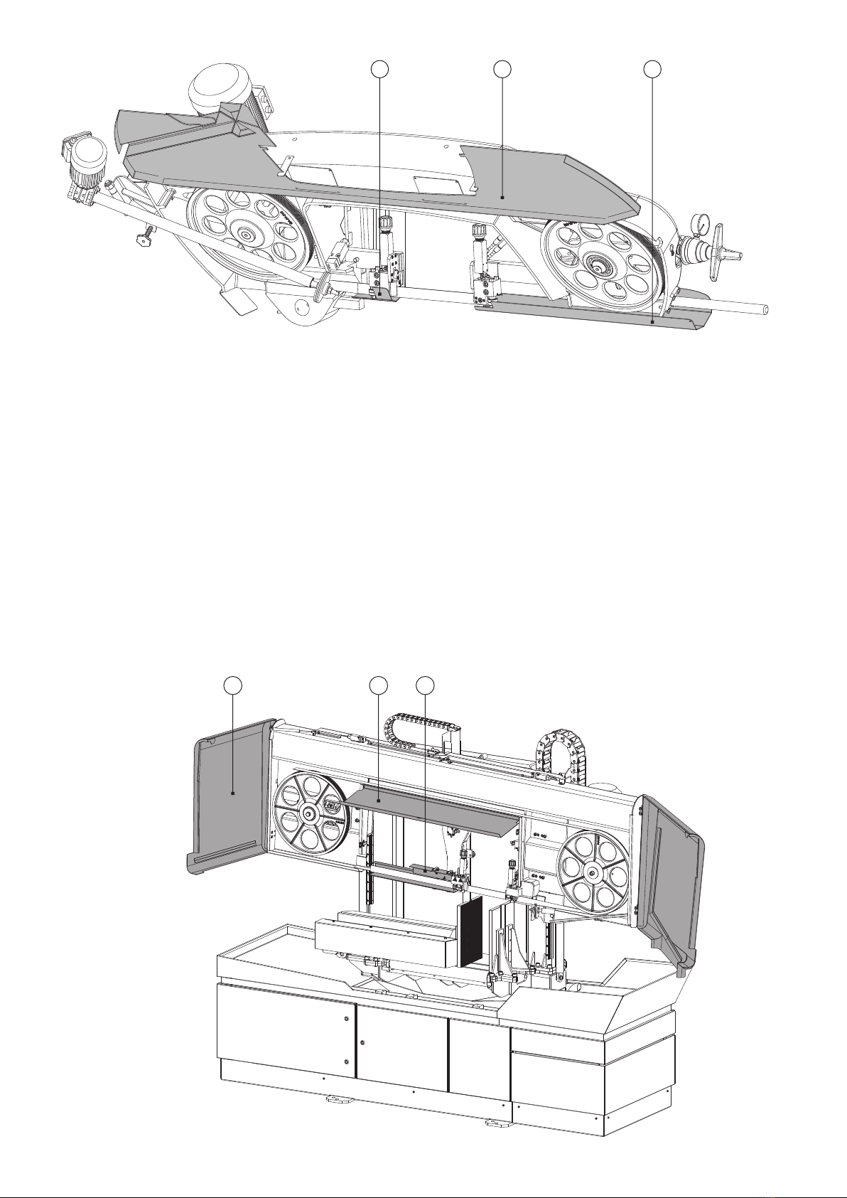
Open/remove the protective covers of the saw blade (see section 4.5.). Use the tensioning star nut to release the wheel and the
blade. In ARG 520 DC, fasten the hardened steel screw in order to release the grip of the blade in the head (see section 4.9.2.). Take
the saw blade off of the moving wheels and push it off the guide heads. Insert the new saw blade in the guide heads. Place it on the
blade wheels (you can control the position of the tensioning wheel by the tensioning star nut). Tension the fitted saw blade. In ARG
520 DC, loosen the contact pressure screw of the saw blade (see Section 4.9.2.). Close/put back the protective covers of the saw
blade and turn on the POWER SWITCH. Turn on the hydraulic unit, switch to the MANUAL MODE and set the minimum saw blade
speed by a SAW BLADE SPEED CONTROLLER. Press the START button of the saw blade to start the saw blade so that it turns
approximately once of the full length. Switch off the POWER SWITCH and secure it against restart. Open/remove the protective
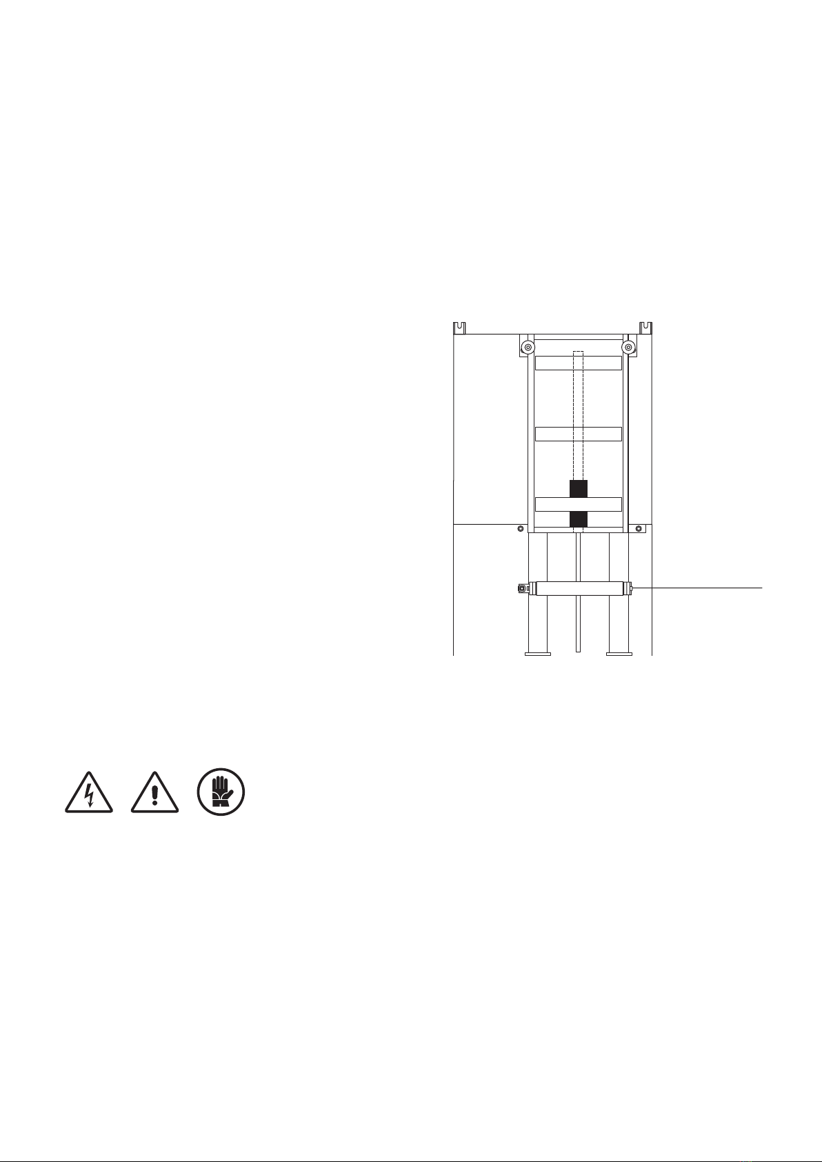
covers of the saw blade to make sure that the saw blade is correctly fitted on the guide heads and correctly installed on the blade
wheels (see figure). The machine is also fitted with a control hole that allows you to check the condition of the saw blade on the
wheels. The hole is covered by a cap.
If the saw blade is not properly set on the wheels, loosen the saw blade a little bit and use the wheel tilting screw to adjust the wheel tilt.
In ARG 520 DC, it is necessary to loosen both fixation screws and, after tilting the wheel, to tighten them again. Tension the saw blade
again and close/put back the protective covers of the saw blade. Turn on the POWER SWITCH and the hydraulic unit. Carry out a
saw blade trial run. Switch off the POWER SWITCH and secure it against restart, open/remove the protective covers of the saw blade
and once again check the placement of the saw blade on the wheels. Repeat the procedure, if required. Close/put back the protective
covers of the saw blade and turn on the POWER SWITCH and the hydraulic unit. Carry out the cutting.
In ARG 520 DC: The spring keeps the saw blade permanently on the moving wheels, even if the hydraulic system is off or the
hydraulic hoses are damaged. WARNING: The spring cannot provide optimum saw blade tension. The limit switch monitors the saw
blade rupture; it turns on when the wheel has reached the end position; thus, the main motor is switched off, which is indicated by the
red lamp on the control board. Caution! While replacing the saw blade, tighten (and after fitting the saw blade loosen again)
the bolts to press down the hardened steel blade guides (ARG 520 DC) before shifting out the saw blade from the guide
heads; see Section 4.9.2.
4.9. Guide Heads Adjustment
4.9.1. Guide heads - adjustment in ARG 260 CF-NC, ARG 300 CF-NC, ARG 300 DCT CF-NC
The correct setting of the bearings and the hardened steel blade guides in the guide heads substantially influences the saw
blade life and the quality of the cut. The eccentrically arranged guide head bearings must be set in such a manner that the saw
blade surface is parallel to the surface of hardened steel blade guides with a minimum play (clearance) between the plates and the
blade.
Guide Head Setting Procedure
Follow the instructions in Section 4.5. in order to tilt/remove the protective covers.Set the movable guide head, so that the distance
between the guide heads is approximately 20 cm. Disconnect the inlet hoses from the coolant valve. Loosen the tensioning star, take
the saw blade off the wheels and push it off the guide heads. Unscrew the guide heads gradually from the fixed and movable bars,
turn them by 180 ° (with bearings and hardened steel blade guides facing upwards) and screw back to the bars. Make sure that the
guide heads are perpendicular to the guide bars and that the height of the guide heads is identical. If you find special washers
between the guide head and the bar, make sure you place them back afterwards. Check the tightening of the fixed hardened steel
blade guides. Insert approximately 30 cm of an old saw blade in the guide heads between the hardened steel blade guides and the
bearings. Set the hardened steel blade guides using the width adjusting screw, so that the saw blade does moves between the guides
without any play and jamming. When the saw blade has been adjusted, set the eccentrically mounted bearings in such a manner that
the bearings do not “cut” the saw blade, but at the same time you have to prevent too much space for the saw blade between the
bearings. When the saw blade moves, the bearings are carried along by the saw blade. Make sure that all bolt connections are tight.
Unscrew the guide heads from the bars. Fit the saw blade on the wheels, check its correct alignment on the wheels and tension the
saw blade. Install both guide heads on the saw blade in the space between the bars and adjust them in the correct position on the
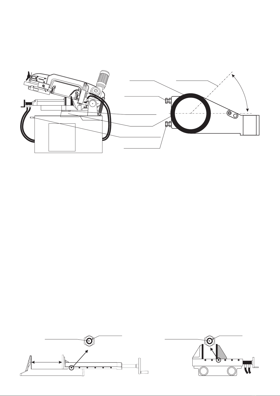
bars.You can achieve the correct guide head height in relation to the saw blade by lifting the guide heads, so that the upper hardened
steel guide in the guide head is about 0.5-1 mm away from the upper edge of the saw blade. See the picture. In this way, the correct
guide head height towards the guide bars is achieved.
Set the guide heads perpendicular to the bars and tighten them. If you fail to achieve perpendicularity, the saw blade will either keep
sliding off or running into the wheels. Put back the protective covers of the saw blade, turn on the POWER SWITCH, press the
SAFETY BUTTON and the hydraulic unit. Carry out a saw blade trial run. Switch off the POWER SWITCH and secure it against
restart, remove the protective covers of the saw blade and once again check the placement of the saw blade on the wheels. Make
a correction, if necessary - see section 4.6. Put back the protective covers of the saw blade, turn on the POWER SWITCH, press the
SAFETY BUTTON and the hydraulic unit. Carry out the cutting. You can watch the video with instructions on www.pilous.cz.
Caution: You can remove the protective covers only if the POWER SWITCH is turned off and
secured against restart or if the machine is disconnected from the mains.
Caution: Danger of injury by the sharp teeth of the saw blade. Use protective gloves. Do not
reach between the wheels and the saw blade.

4.9.2. Guide heads - adjustment ARG 330 CF-NC, ARG 330 DC CF-NC, ARG 520 DC CF-NC
The correct setting of the bearings and the hardened steel blade guides in the guide heads substantially influences the saw blade life
and the quality of the cut. The eccentrically arranged guide head bearings must be set in such a manner that the saw blade surface is
parallel to the surface of hardened steel blade guides. One of the hardened steel blade guides is fixed, the other is setting (ARG 330
type) or floating and pressed to the saw blade by a set of springs (ARG 520 DC type).
Caution! While replacing the saw blade, tighten (and after fitting the saw blade release again) the bolts to press down the
hardened steel blade guides before shifting out the saw blade from the guide heads (ARG 520 DC type).
ECCENTRIC BEARING SCREW
HARDENED STEEL
BLADE GUIDES WIDTH
ADJUSTING SCREW
ECCENTRICALLY
ARRANGED BEARINGS
HARDENED STEEL
BLADE GUIDE SCREW
MOVABLE HARDENED
STEEL BLADE GUIDES
FIXED HARDENED
STEEL BLADE GUIDES
MOVABLE
GUIDE BAR
FIXED
GUIDE BAR
MOVING GUIDE HEAD
GUIDE HEAD SCREW
SAW BLADE
Incorrect saw blade guidance
Correct saw blade guidance
to center between guide bearings
UPPER HARDENED
STEEL BLADE GUIDES
Approximately 0,5-1 mm
WARNING!
There has to be a clearance
COOLANT VALVE
FIXED GUIDE HEAD
HARDENED STEEL
BLADE GUIDE SCREW

Correct saw
blade guidance
to center between
guide bearings
Incorrect saw
blade guidance GUIDE HEAD WITH CONTROL HEAD ATTACHED
GUIDE HEAD TILT SETTING SCREWS
HEAD CONNECTING BOARD SCREWS
CONTROL HEAD
SCREW LOOSENING THE BLADE GRIP
GUIDE HEAD BOLTS
BOLTS OF FIXED HARDENED STEEL BLADE GUIDES
CONTROL SYSTEM BEARINGS
CONTROL SYSTEM ROLLER
FLOATING HARDENED STEEL BLADE GUIDES LINER BOLTS
CONTROL CYLINDER LINER
ECCENTRICALLY ARRANGED BEARINGS
FLOATING HARDENED STEEL BLADE GUIDES SPRINGS
FIXED GUIDE HEAD
MOVING GUIDE HEAD
HARDENED STEEL BLADE GUIDES PRESSURE SCREW

Machines of the type ARG 330 are not fitted with springs for floating hardened steel blade guides. Adjustable contact pressure of
floating hardened steel guides is facilitated by screws.
Guide Head Setting Procedure
Raise the saw blade approx. 30 mm (in ARG 300) above the fixed vice jaw (70 mm in ARG 520). Switch off the POWER SWITCH and
secure it against restart. Disconnect the coolant supply hoses from the guide heads and the control head (the hydraulic hoses must
never be disconnected!). Loosen the tensioning star nut in order to loosen the saw blade. Open/remove the protective covers of the
saw blade. In ARG 520 DC, fasten the hardened steel blade guides screw in order to release the grip of the blade in the head. Take
the saw blade off the moving wheels and push it off the guide heads. Unscrew the guide heads gradually from the fixed and moving
guide bars and clean them thoroughly. Fasten the guide heads to the fixture approx. 350 mm from each other and turn them through
180° (with bearings and hardened steel blade guides upwards). Make sure that the guide heads are perpendicular to the guide bars
and that the height of the guide heads is identical. Check the tightening of the fixed hardened steel blade guides. Insert
approximately 50 cm of an old saw blade in the guide heads between the hardened steel blade guides and the bearings. When the
saw blade has been adjusted, set the eccentrically mounted bearings in such a manner that the bearings do not “cut” the saw blade,
but at the same time you have to prevent too much space for the saw blade between the bearings. When the saw blade moves, the
bearings are carried along by the saw blade. Adjust the control bearing with the control cylinder liner so that the bearing axis is
perpendicular to the saw blade. Make sure that all bolt connections are tight. Unscrew the guide heads from the fixture. Fit the saw
blade on the wheels, check its correct alignment on the wheels and tension the saw blade. Install both guide heads on the saw blade
in the space between the bars and adjust them in the correct position on the bars.In this way, the correct guide head height towards
the guide bars is achieved. Adjust the heads in such a way that the saw blade is in perpendicular position to the machine table and
tighten them. Connect the coolant hoses and the saw blade pressure control heads. Close/put back the protective covers of the saw
blade and turn on the POWER SWITCH. Switch on the hydraulic unit and carry out a short trial run of the saw blade. Switch off the
POWER SWITCH and secure it against restart. Open/remove the protective covers of the saw blade and check the placement of the
saw blade on the wheels. Make a correction, if necessary - see section 4.8.. Close/put back the protective covers of the saw blade
and turn on the POWER SWITCH and the hydraulic unit. Carry out the cutting.
4.10. Hydraulic Unit
The hydraulic unit is installed in the machine base. It lifts the band saw arm, feeds the saw blade to the cut, feeds the arm into the cut
and clamps and unclamps the vice. The HYDRAULIC UNIT - START button is used for activation of the hydraulic unit when the
MAIN SWITCH is turned on. The units in all machines are identical, only the ARG 520 DC CF-NC includes an extra block - marked in
grey.
Hydraulic unit ARG 260 CF-NC, ARG 300 CF-NC, ARG 300 DCT CF-NC, ARG 330 CF-NC, ARG 330 DC CF-NC
TANK
ELECTRIC MOTOR PUMP RETURN FILTER
ONE-WAY VALVE
VALVE
PRESSURE
GAUGE
PRESSURE
REDUCTION VALVE
FILLING CAP RELIEF
SWITCHBOARD SWITCHBOARD
PRESSURE SWITCH
OF THE FIXED VICE
LOCK
PRESSURE SWITCH
OF THE MOVABLE VICE
TRANSPORT CAPS

4.10.1. Vice Clamping Force Setting
The hydraulic unit is fitted with a PRESSURE REDUCTION VALVE. It enables setting the required vice clamping force
depending on the kind of the workpiece within the range:
13-35 bar in ARG 260 CF-NC, ARG 300 CF-NC, ARG 300 DCT CF-NC, ARG 330 CF-NC, ARG 330 DC CF-NC,
15-30 bar in ARG 520 DC CF-NC.
Turning the PRESSURE REDUCTION VALVE to the left reduces the pressure, while turning it to the right increases the
pressure (see picture). The specified pressure is shown on the pressure gauge.
If the pressure is set below a clamping force smaller than 13/15 bar, the safety PRESSURE SWITCH OF THE VICE does not
switch on and the saw blade does not start.
VICE PRESSURE
REDUCTION VALVE
TANK
ELECTRIC MOTOR PUMP RETURN FILTER
PRESSURE
GAUGE
PRESSURE
REDUCTION VALVE
SWITCHBOARD SWITCHBOARDLOCK
PRESSURE SWITCH
OF THE FIXED VICE
PRESSURE SWITCH
OF THE MOVABLE VICE
Hydraulic unit ARG 520 DC CF-NC
ONE-WAY VALVE
VALVE
FILLING CAP RELIEF
TRANSPORT CAPS

4.11. Cooling System
The pump and the coolant tank, which are mounted in the machine base, are the basic elements of the cooling system. The coolant
pump conveys the coolant via hoses, valves and guide heads to the saw blade. The main cooling via the guide heads is
complemented by an additional cooling system. The coolant quantity is regulated with valves. The coolant cools down and lubricates
the saw blade and flushes away metal chips. The pump switches on and off when the saw blade drive is started or shut down. The
pump can be started during the machine cleaning and also when the saw blade or the hydraulic unit is off. Activate the machine
cleaning menu - chips conveyor and manually start the coolant pump.
When handling coolants, risks linked to hazardous substances cannot be avoided. Observe the manufacturer's and/or
your company's instructions and recommendations referring to safe coolant handling.
If you fill too much coolant, an overflow resulting in spilling the coolant under the saw may occur.
SUPPLY HOSE
VALVE
MESH
COOLANT TANK
PUMP
ADDITIONAL COOLING SPRAY GUN

5. Commissioning
5.2. Cutting Procedure
Danger of injury!
No cover on the saw blade in the cutting area!
High risk of injury in the operating area of the blade!
5.1. Security Check
Is everything in perfect condition with regard to safety and technical condition?
Are all protective devices mounted properly?
1) Unlock the arm. In ARG 520 DC automat, unscrew the M10x60 bolt (see section 3.5.) on each side of the column and release the
arm.
2) Turn on the POWER SWITCH. The operation system turns on the control panel display.
A yellow screen will appear, showing: “Close the arm cover, unlock the TOTAL STOP and press the yellow-lit SAFETY button”.
3) The MAIN MENU will initialize. Turn on the HYDRAULIC UNIT START
4) Choose MANUAL , SEMI-AUTOMATIC or AUTOMATIC MODE . The performance of the first cut will be described
only for MANUAL and AUTOMATIC MODE.
MANUAL mode (see Section 4.1.4)
5) You have selected MANUAL MODE .
6) Turn on the HYDRAULIC UNIT START , unless you have already done so in step 3).
7) Open the vices L and R hydraulically . In ARG 260, 300 and 330, open the vice also manually, using a rotary wheel. In ARG 520
DC automat, press it and hold it. In ARG 520 DC automat, the bar simultaneously moves along the movable guide head with the
vice. In ARG 260,300,330 it is necessary to move the bar of the movable guide head manually in front of the movable jaw.
8) Lift the arm up to the upper position (see Section 4.1.4) so that the saw blade is located above the cut material. Stop lifting .
In case the saw blade is now too high above the material, you can adjust this height the following way.
9) Insert the material manually under your saw blade to the desired length of cut.
10) Clamp the vice R .
11) In ARG 260, 300 and 330, move the movable bar in a way that allows moving the guide head towards the cut workpiece to the
distance of 30-50 mm and shut off the control valve.
12) If the arm is too high above the material, lower it down and control the speed of the descent using the control valve. Stop the
descent and shut off the CONTROL VALVE.
13) Press the SAW BLADE START button(see Sec. 4.1.4), to start the saw blade. Set the optimum blade speed.
14) Start the arm descent .
15) Set the optimum speed of the arm descent to the cut by gradual loosening of the CONTROL VALVE and perform the cut.
16) Turn off the SAW BLADE STOP .
17) Lift the arm up to the required upper position and turn off the arm uplift.
18) Open the vice R .
19) Insert a new workpiece, or move the current one.
You can use the servo feed system of the feed vice and move to material after entering the cut length on the screen. The feed vice L
feeds, however, only pieces up to 500 mm, in ARG 520 is it 600 mm.
Click here to confirm the value. After feeding and removing the material, you can manually measure the length of the cut material
and adjust the whole process.
MANU AL MODE
0 9 : 2 0 : 0 3 0 8 / 1 0 / 2 0 1 6
CORRECTI
ON
L R
AMMETER
65
15 90
BLADE SPEED m/min
0.0 A
mm
123.5
123.5
1.12
HEIGHT
mm
0

Care and maintenance is absolutely necessary to maintain the functionality of the machine and its components. This includes: check
and adjustment of band saw guide heads • machine cleaning • metal chips removal • removing metal chips from the internal part of the
band saw arm • coolant replacement • lubrication of sliding surfaces • checking of supply lines for damage • vice checks • screw
connection checks • limit switch checks
Check protective devices
Check the protection devices for possible damages and faults prior to the start of everyday work.
Check power cable
Check in regular intervals, at least once a week: integrity of electric installation • integrity of connections and relief from
pulling
6.1. Cleaning
Clean the machine in regular intervals (always at the end of the shift, or if required, during the shift). Use suitable cleaning agents. Do
not use solvents (e.g. nitro thinner). Do not use compressed air! Compressed air would blow delicate chips and dirt particles under
sliding elements or endanger the health of personnel by flying particles.
Danger of injury!
Carry out the maintenance work only if the power switch is off or if the machine is disconnected from the mains.
AUTOMATIC MODE (see Section 4.1.2)
1) You have selected AUTOMATIC MODE .
2) Turn on the HYDRAULIC UNIT START , unless you have already done so in step 3).
3) Open the vice in ARG 260, 300 and 330 manually, using a rotary wheel. In ARG 520 DVC automat, press it and hold it. In ARG
520 DC automat,,the bar simultaneously moves along the movable guide head with the vice. In ARG 260, 300 and 330 is it necessary
to move the bar of the movable guide head manually in front of the fixed bar.
4) Click on the “SERIES” button, enter into any line, for example line 1, the length, the number of pieces, the height of the material, the
type of the feed (usually gradual >> for short pieces, return > for longer pieces) and then confirm the whole series (see Section
4.1.5). To exit the screen, press the ESC button. For further assistance with filling in of the height of the cut material, you can use the
table "ARM UPLIFT HEIGHT H SETTING" under the button (only in selected machines). Do not fill in value which is lesser than
40 mm.
5) Click on the "PRIMARY POSITION" button, the arm ascends to the highest position and the feeding vice arrives at the zero
position. Thus reaches the vice as well as the arm their primary positions and the machine becomes ready for the insertion of new
material.
6) Insert material. Insert the material underneath the blade in the case that you will want to downcut the material, i.e. deburr the
surface and, at the same time, the downcutting calibrates the saw to the zero level. After downcutting, the saw will feed the exact
length of the newly set workpiece. In case you do not wish to execute any downcutting, move the material as close as possible to the
saw blade. The accuracy, with which you perform this movement, will be included in the resulting workpiece.
7) Make sure the control valve is closed.
8) Turn on the SAW BLADE START button and the Correction pop-up window will appear. Click on the continue button to resume the
cycle. The saw blade will get started and the material will be clamped. Set the desired saw blade speed by a SAW BLADE SPEED
CONTROLLER.
9) The arm will execute the cut and will subsequently ascend to the height that has been preset in the series. According to the set
number of pieces, next cut will be performed or the series will be ended. The overall duration of the series will appear in the pop-up
window.
10) Set up a new series or insert new material to continue cutting.
6. Machine Maintenance
H
NC MODE
0 9 : 2 0 : 0 3 0 8 / 1 0 / 2 0 1 6
SERIES
SE RIES LE NGTH P I ECES FE ED
1 35 7 10
2 15 9 15
5 35 8 75
7 58 6 33
8 25 5 45
SE RIES LE NGTH P I ECES FE ED
9 33 9 87
12 98 2 65
14 24 4 27
15
250 13
16 36 5 65
KERF
PRIMARY
POSITION
START
L R

The coolant tank cannot be removed from the machine base during the maintenance and cleaning. Access to it is facilitated through
the lid in the base. Caution: Used coolant belongs to special waste category!
Our recommendations: Regular cleaning and maintenance of the coolant increases the service life and functionality of the coolant
pump. If possible, use the coolants miscible with water, non-irritant to skin and with high protection against aging and corrosion. Min.
Check the volume of oil in the coolant at least once a week. Optimum lubrication increases cutting productivity. There is a barrier in
the coolant tank that separates the space for filtering impurities. This space should be cleaned during routine checks depending on
the kind of material to be cut.
6.4. Lubrication
Regular lubrication and cleaning extend the life and functionality of the machine. While making routine checks, make sure there is
sufficient grease on the vice friction surfaces. Observe lubrication of greasing points according to the lubrication plan for individual
machines within every 40 hours or so. The linear guides must be greased or oiled according to manufacturer's instructions. The first
lubrication with lithium soap-based grease class NGLI-2 is applied during the assembly. Spiral spring covers of the ball screw have to
be periodically cleaned from gross impurities and greased - if possible, with the oil spray W44T Turbo spray approx. every 20 hours.
Dense rosin oils are not suitable. Their usage can lead to blocking of the threads and breakage of the spring. By using unsuitable oils,
the warranty becomes invalid.
6.4.1. Lubrication points in ARG 260 CF-NC
When handling coolants, risks linked to hazardous substances cannot be avoided. Observe the regulations and
recommendations (operating instructions by professional associations or your company) related to safe
handling of coolants.
Correct cutting angles will be achieved when the bearing surfaces for the workpiece and the surfaces of gripping jaws are free from
metal chips or other impurities. In order to retain proper function of the machine, make sure that the space around moving parts of the
machine is free of wood chips. Should this prerequisite not be maintained, a great risk of machine damage arises. For the wood chip
removal, use of a spray gun is recommended.
Observe the instructions and recommendations concerning safe disposal of waste produced during
operation.
6.3. Coolant system cleaning
6.2. Removal/disposal of chips

6.4.3. ARG 520 DC CF-NCLubrication points in
6.4.2. Lubrication points in ARG 300 CF-NC, ARG 330 CF-NC + ARG 300 DCT CF-NC, ARG 330 DC CF-NC

FILLING CAP
OIL LEVEL
RETURN FILTER
TRANSPORT CAP
TRANSPORT CAP
LID
SCREW M10
TANK
The following principles must be adhered to during the assembly of hydraulic circuit elements and piping. The basic rule in cleaning
and maintenance is cleanliness and orderliness! The hydraulic circuit consists of very precise elements and it is very difficult,
complicated and costly to remove any contamination and its consequences. Remove the protective cap just before putting the device
into operation. Consistently check the oil level on the gauge located on the filling cap on the hydraulic unit.
6.5.1. Work safety
The hydraulic circuits are reliable and safe even when under high pressure, if all the elements are appropriately sized. However,
a breakdown due to material defect or fatigue can occur in them, which could endanger the safety of the staff or contaminate the
environment with oil. Examples of visible defects:
• dripping oil;
• destruction of pressure-loaded circuit parts.
Oil dripping from an untight connection or another spot, which collects on the floor, can cause slipping and falling of persons or floor
damage and leakage to the environment, it can cause extensive pollution of large quantities of water. The destruction of pressure -
loaded circuit parts does not lead to any explosion. If the crack is small, oil is disperses to the environment in the form of mist, if the
crack is large, mostly the whole tank will discharge. The destruction of pressure hoses will manifest itself by oil leaking, but very
frequently also by bursting of hose socket. In such case, the hose can spring up and cause a serious injury. Both failures cause
pollution of the environment and even a small spark can lead to a huge fire.
It follows that the following principles must be taken into account for installation and operation of hydraulic circuits:
• keep the machine clean, sprinkle the leaked oil with wood chips or VAPEX absorbate, sweep the floor, clean it with an
appropriate solvent and dry;
• while dismantling, prevent oil spilling by installing suitable containers;
• units and all hydraulic elements including hoses and pipelines must be protected against external mechanical damage and heat
resources;
• if the circuit is under pressure, do not come close to the pipelines and hoses, particularly do not expose your face;
• should oil be spilled into eyes, flush eyes with Ophtal or any other suitable agent immediately;
• if the anti-flaming agent is in eyes, seek medical help immediately.
• do not smoke or use open fire in the storage facility and near the units and hydromotors;
• shut down the hydrogenerator drive whenever you make any changes or repairs;
• electrical equipment must comply with ESC regulations;
• containers with industrial petrol may only be used in specifically designed spaces and must be covered with a cover or a closure at
all times;
• hydromotors, which could start turning automatically in case that the driving hydrogenerator switches off (pressure drop), must be
mechanically or hydraulically locked against this possibility;
• all hydraulic systems and circuits must be protected by a pressure valve against an overload, as well as hydromotors, which could
become overloaded after hydraulic locking;
• the person responsible for maintenance and setting of the hydraulic unit must be appointed.
The afore mentioned principles of safety at work are not exhaustive.
There are different conditions for each hydraulic circuit and different possibilities of endangering the environment. The afore
mentioned, however, should reduce the accident rate and improve the working conditions of users.
6.5. Principles of Hydraulic Unit Maintenance
This manual suits for next models
5
Table of contents
Other Pilous Saw manuals