Content :
7. Putting into operation
7.1. Safety control
7.2. First cut
8. Machine maintenance
8.1. Maintenance and control
8.2. Repairs
9. Errors - reasons and elimination
10. Electrical scheme and device lay-out
10.1. Electrical scheme
ARG 180, 200 Plus, 220 Plus, 230 Standard
10.2. Electrical scheme ARG 230, ARG 230 Plus,
ARG 240, ARG 240 Plus, ARG 290 Plus
10.3. Electrical device lay-out
180, 200 Plus, 220 Plus, 230 Standard
10.4. Electrical device lay-out ARG 230, ARG 230 Plus,
ARG 240, ARG 240 Plus, ARG 290 Plus
11. Assembly
11.1. Guiding heads assembly
11.2. Idler wheel assembly
11.3. Table, pivot and vice assembly
11.3.1. Table, pivot and vice assembly ARG 180
11.3.2. Turning table and pivot assembly
ARG 200 Plus, ARG 220 Plus
11.3.3. Vice assembly ARG 200 Plus, ARG 220 Plus
11.3.4. Table, pivot and vice assembly
ARG 230 Standard, ARG 230, ARG 240
11.3.5. Table, turning table, pivot and vice assembly
ARG 230 Plus, ARG 240 Plus, ARG 290 Plus
11.4. Drive assembly
11.5. Oil damper assembly
11.6. Coolant assembly
0. In general
0.1. Safety provisions
0.2. Scope of use / use by determination
0.3. Requirements concerning operators
0.4. Requirements concerning machines -
safety equipments
0.5. Protective covers
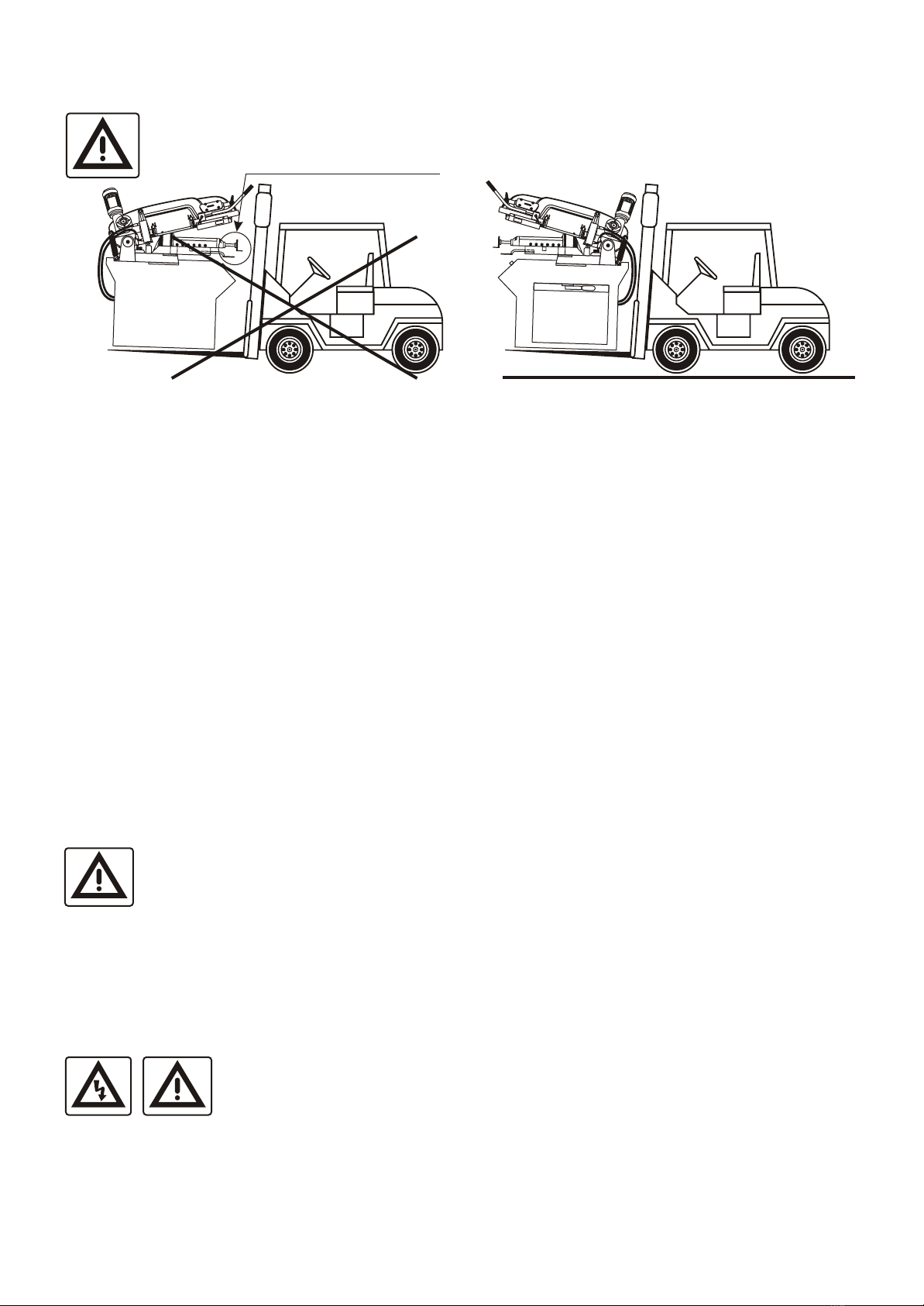
1. Transport and storage
1.1. Surface treatment
1.2. Packing
1.3. Installation
1.4. Dismantling
1.5. Disposal
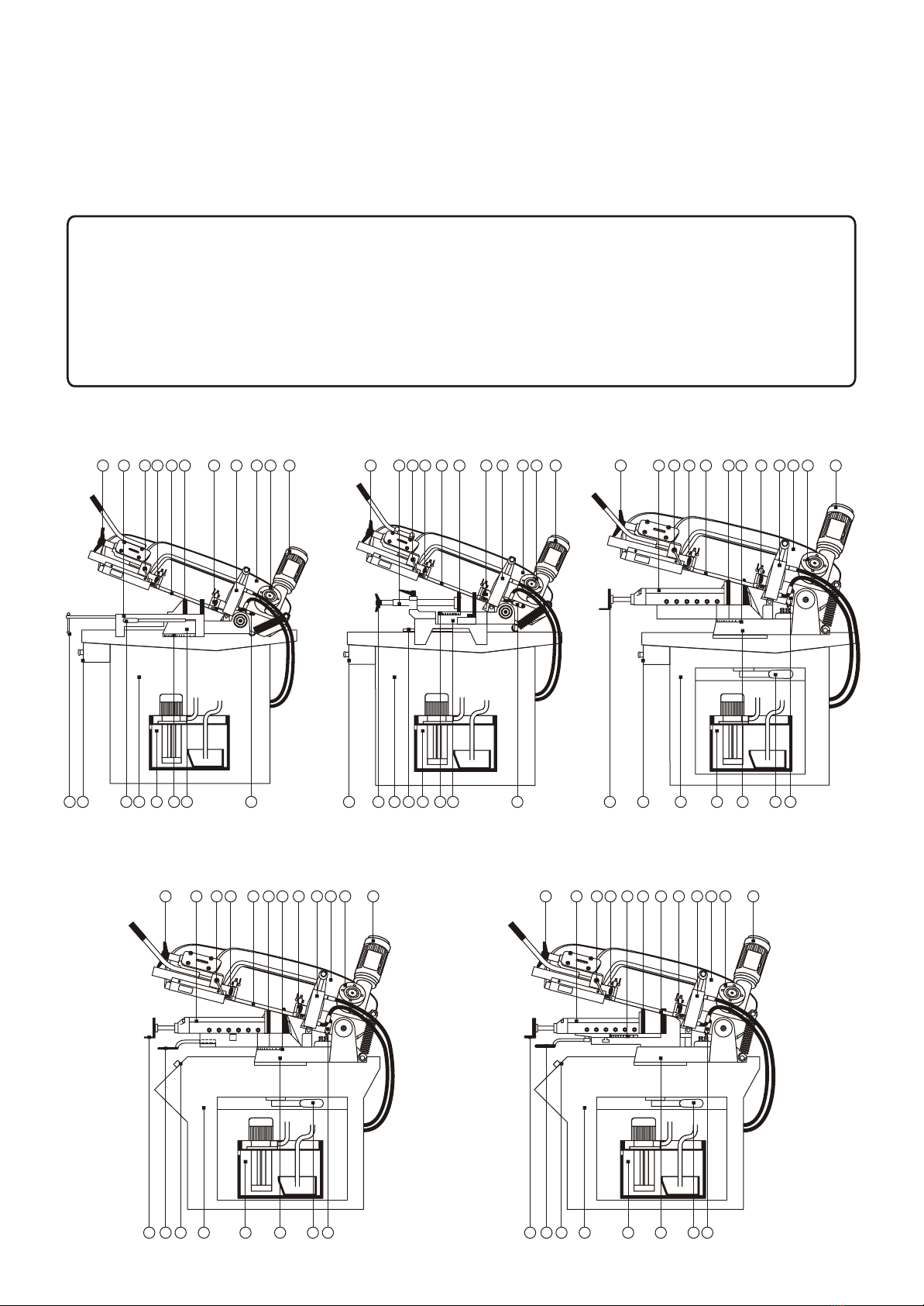
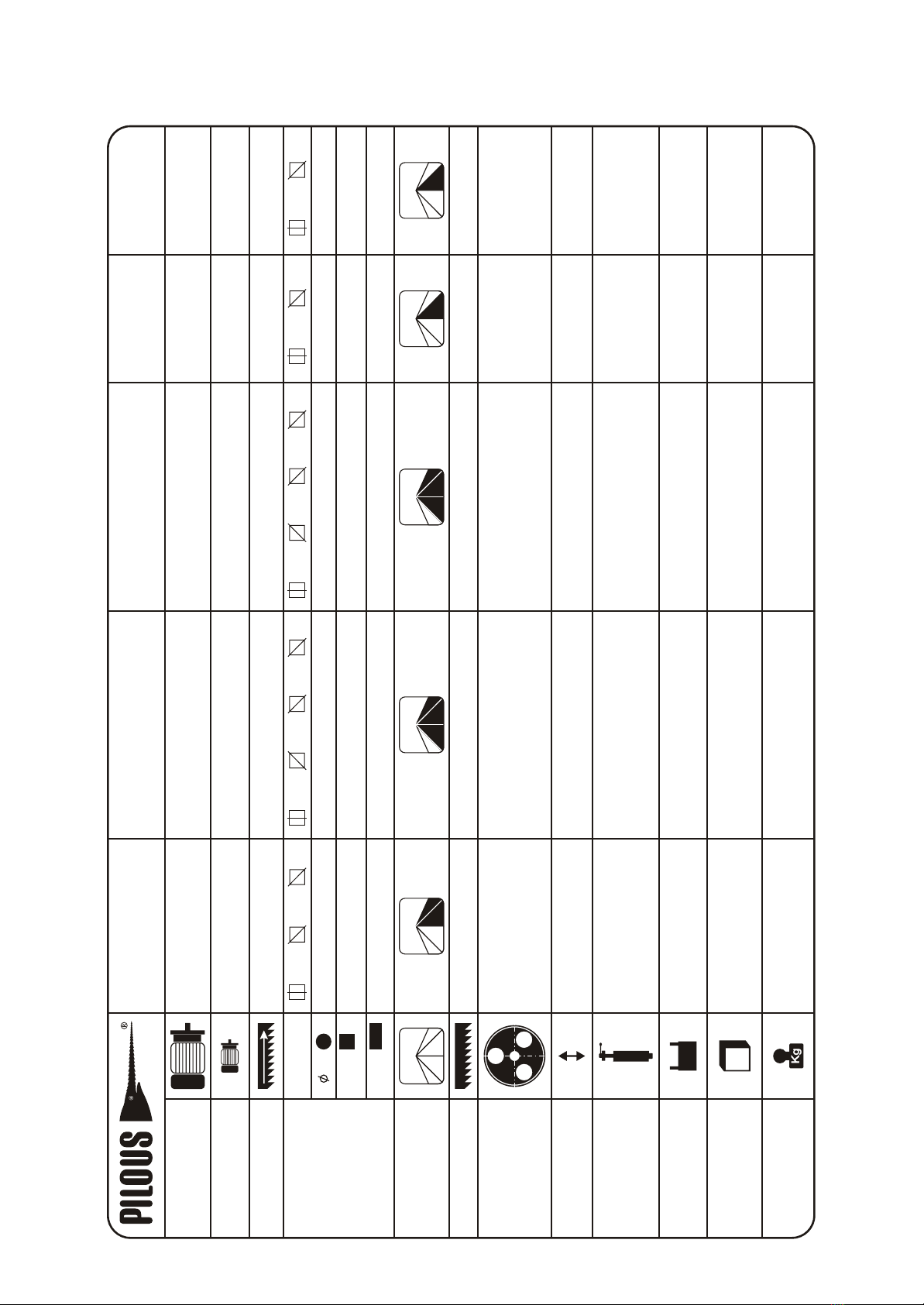
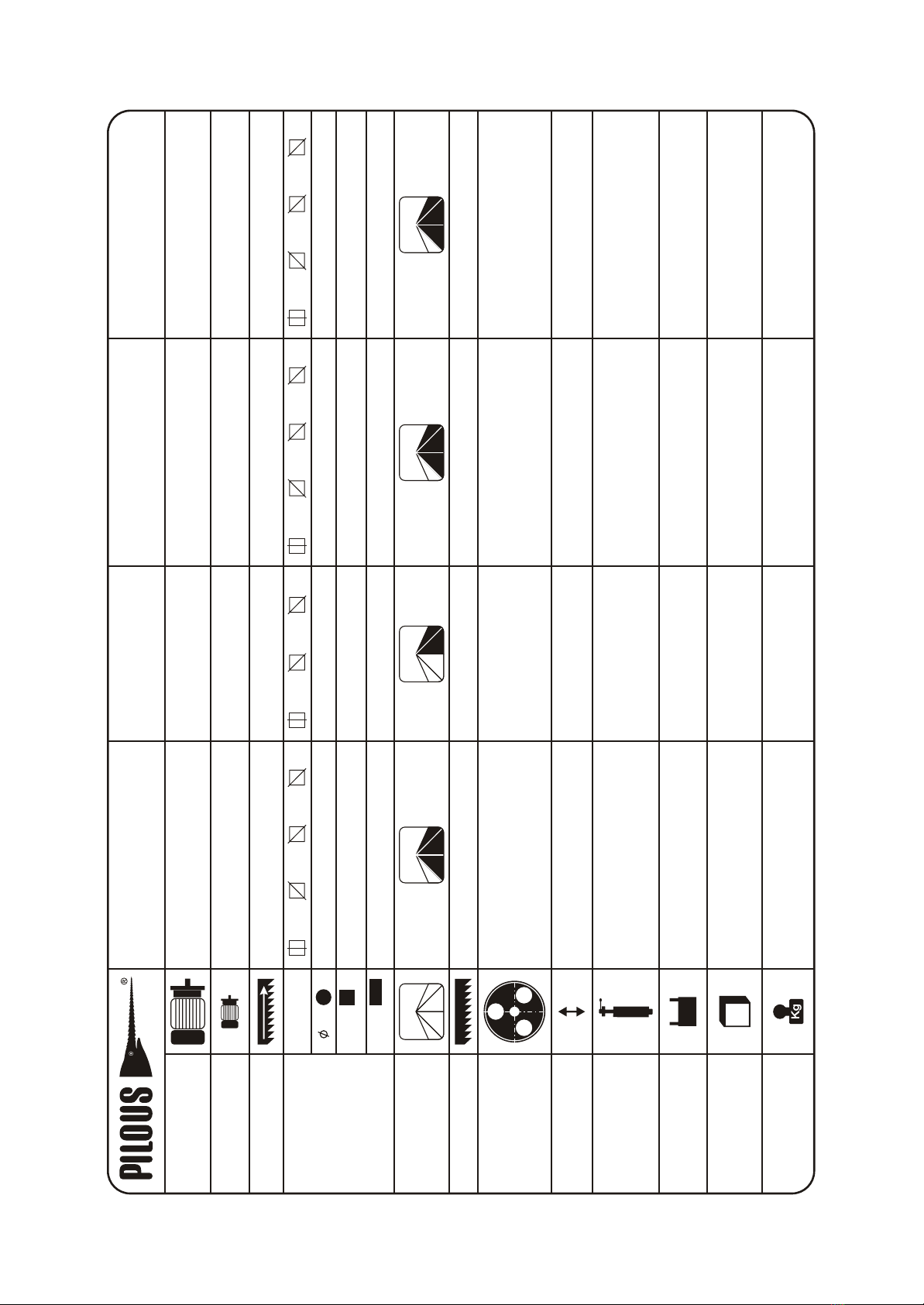
2. Machine data
3. Technical data
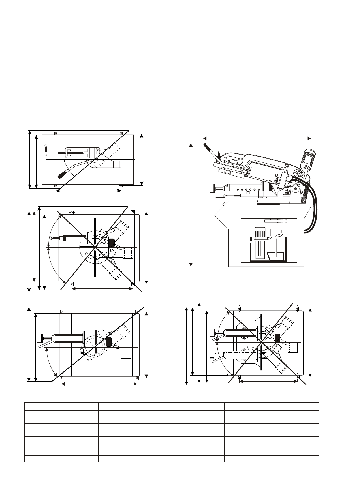
4. Installation
4.1. Space requirements
4.2. Machine installation
4.3. Connection to energy supplies
5. Machine description
5.1. Band guide
5.2. Band exchange, tensioning and adjustment
5.3. Guide heads - adjustment
5.4. Vice - Workpiece clamping
5.4.2. Setting of cutting angle
5.5. Control panel
5.5.1. Control panel ARG 180, ARG 200 Plus,
ARG 220 Plus, ARG 230 Standard
5.5.2. Control panel ARG 230, ARG 230 Plus,
ARG 240, ARG 240 Plus, ARG 290 Plus
5.7. Cooling equipment
6. Saw bands
6.1. Saw band design
6.2. Band tooth selection
6.3. Workpiece clamping
6.4. Running-in the bands
6.5. Factors influencing band life
6.6. Recommended values for cutting
5.4.1. Vice side clearance setting
5.6. Oil Damper - saw band feed into cut
Dear customer,
thank you for buying our product and we wish you a lot of success with it. For proper machine function please pay an
attention to this instruction manual.
© 2004 All rights particularly the right to make copies of, to distribute and translate this instruction manual are reserved.
No part of this instruction manual may be reproduced in any form (printing, microfilm or others) or sorted, processed,
copied or distributed by using electronic systems without permission of PILOUS.