Pilous ARG 380 plus SAF User manual

INSTRUCTION MANUAL
BANDSAW
BRUKERVEILEDNING
BÅNDSAG
INSTRUKTIONSBOK
BANDSÅG
GB
NO
SE
ARG 380 Plus S.A.F.
ARG 400 Plus S.A.F. 20875-0204, -5520
ARG 500 Plus S.A.F. 20875-0307, -5512

1
ENGLISH
Dear customer,
Thank you for buying our product. Please read through this instruction
carefully. It will help you understand the machine and operate it smoothly.
© 2007 All rights, particularly the right to make copies of, to distribute and
translate this instruction manual, are reserved. No part of this instruction
manual may be reproduced in any form (printing, microfilm or others) or
stored, processed, copied or distribured by using electronic systems wit-
hout permission of PILOUS.
Contents:
0. In General ......................................................................................1
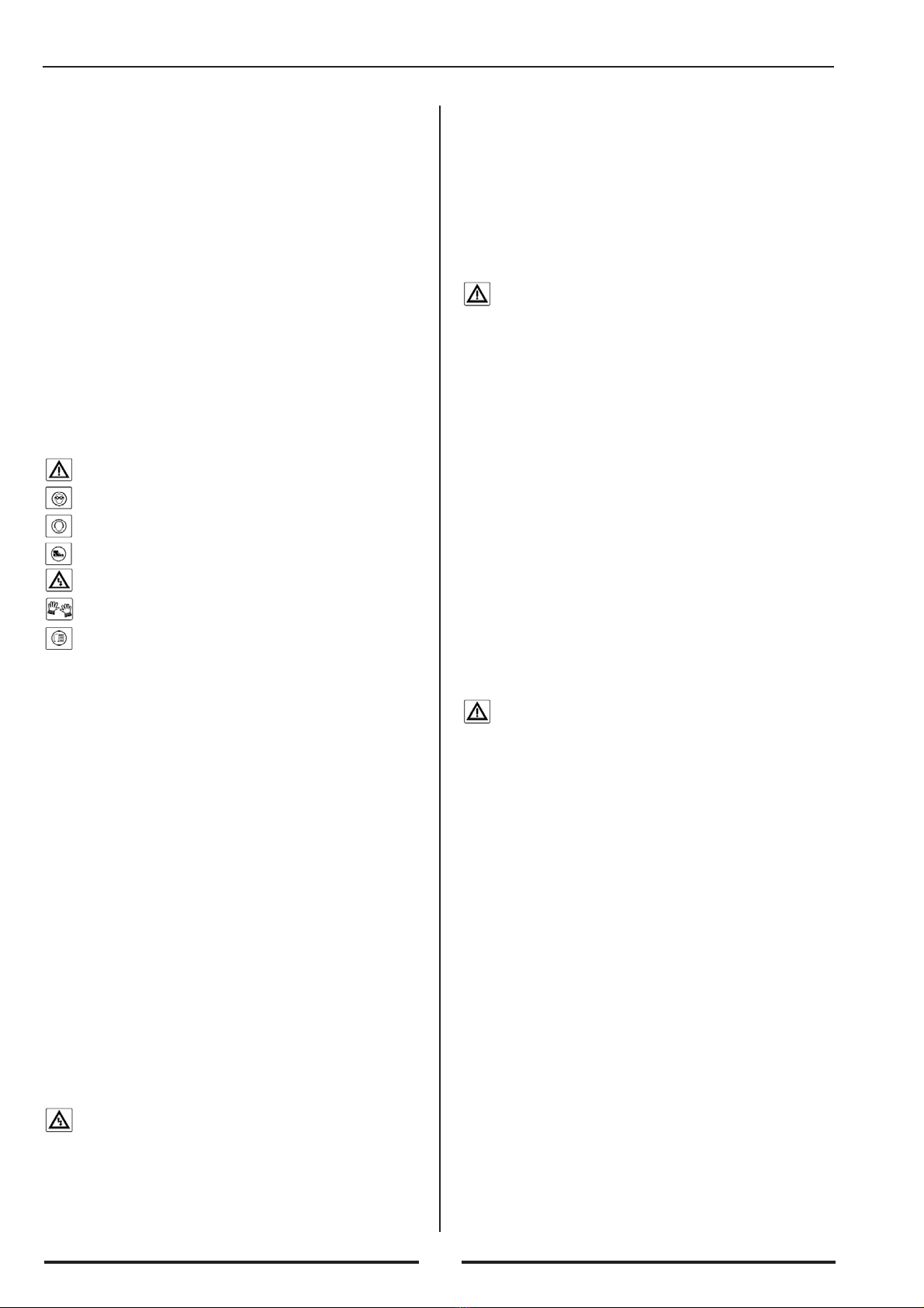
0.1. Safety Provisions.............................................................................2
0.2. Scope of Use / Use acc. to Specification........................................2
0.3. Requirements Concerning Operators..............................................2
0.4. Requirements Concerning Machine- Protective Enclosures ..........2
0.5. Protective Enclosures......................................................................2
1. Transport and Storage..................................................................2
1.1. Surface Treatment ...........................................................................2
1.2. Packing............................................................................................2
1.3. Dismantling/ Repackaging..............................................................2
1.4. Disposal...........................................................................................3
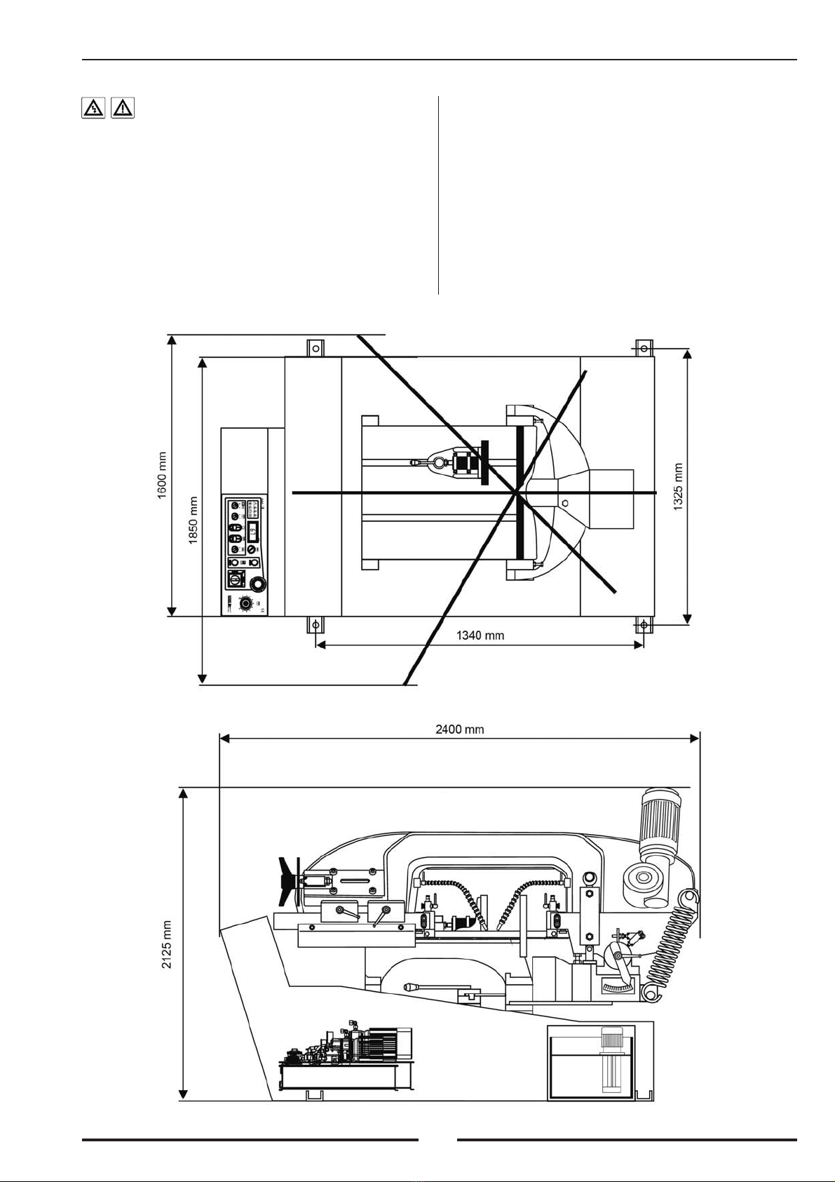
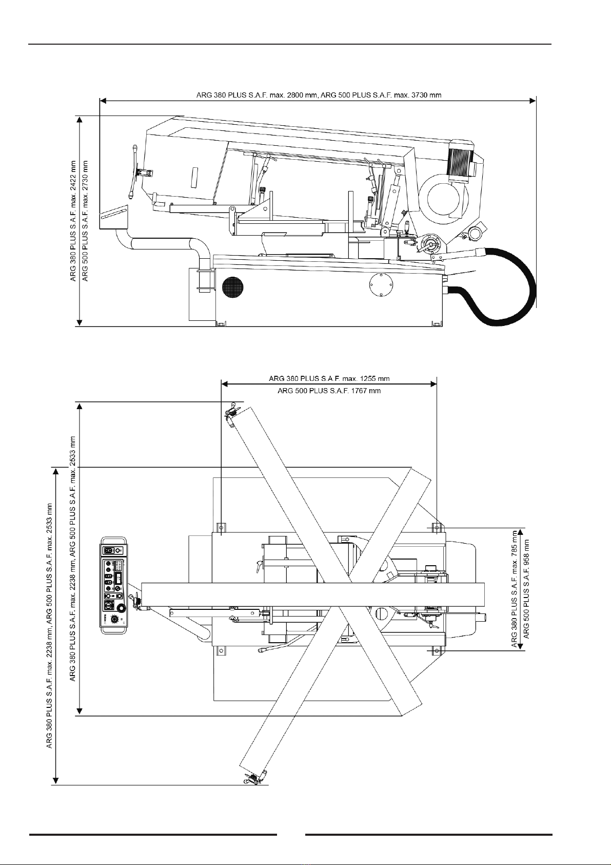
2. Installation .....................................................................................3
2.1. Space Requirements........................................................................3
2.2. Dismantling of Transport Beams and Machine Alignment ............5
2.3. Machine Installation........................................................................5
2.4. Connection to Energy Supplies.......................................................5
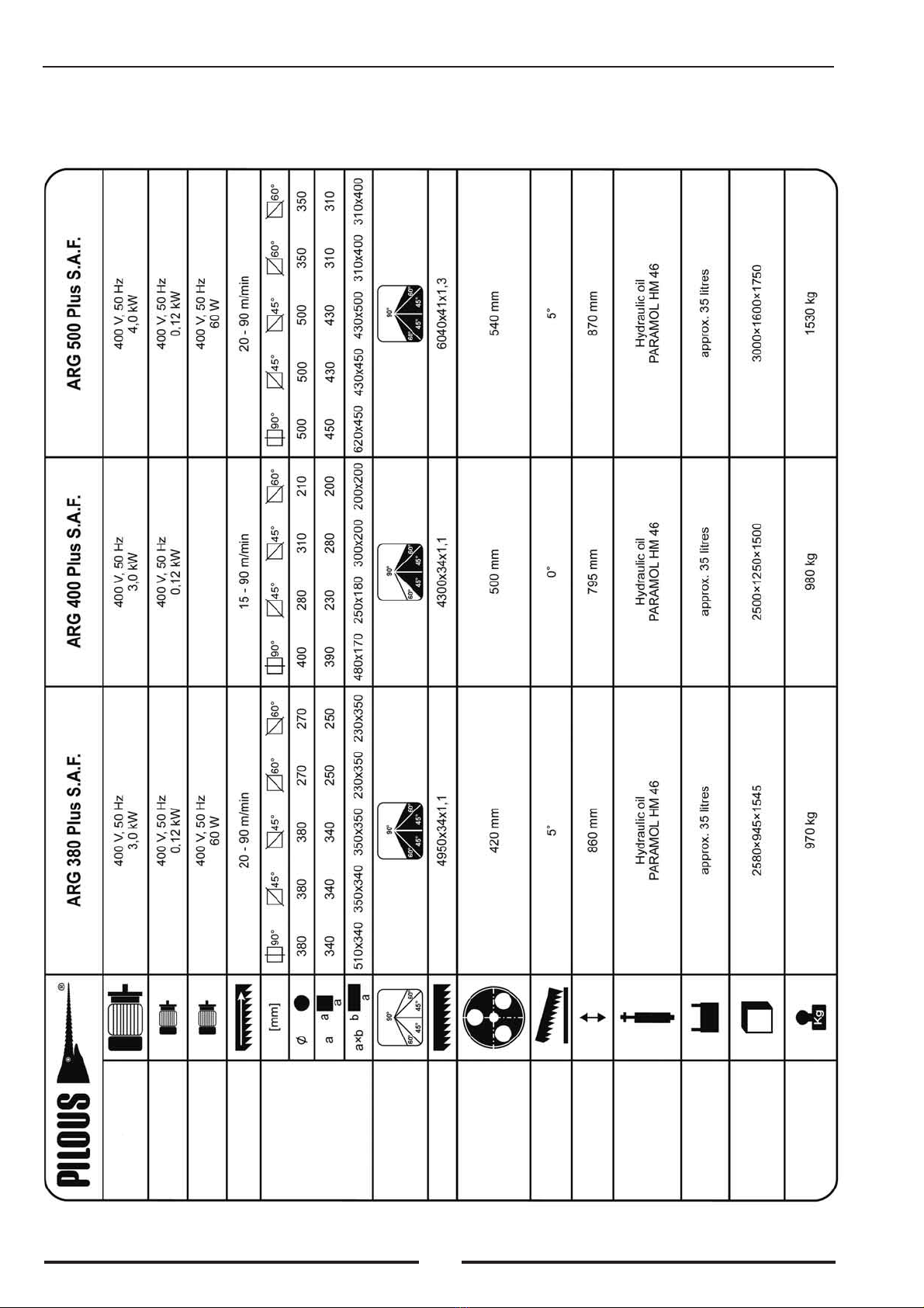
3. Technical Data ...............................................................................6
4. Machine Parameters.....................................................................7
5. Machine Description...................................................................10
5.1. Vice ...............................................................................................10
5.1.1. Setting of Cutting Angle ...............................................................10
5.1.2. Material Clamping ........................................................................10
5.2. Saw Blade Feed into Cutting Position..........................................12
5.2.1. Saw Blade Feed into Cutting Position-Control valve...................12
5.3. Hydraulic Unit...............................................................................12
5.3.1. Hydraulic Unit...............................................................................12
5.3.2. Setting of Vice Clamping Force....................................................12
5.4. Setting of Band Saw Head Stroke Height ....................................13
5.5. Saw Blade Guide...........................................................................14
5.6. Saw Blade Replacement, Tension and Setting..............................14
5.7. Guide Heads - Setting ...................................................................14
5.8. Regulation of Saw Blade Cutting Pressure...................................16
5.9. Control Panel.................................................................................16
5.10. Cooling System.............................................................................21
6. Saw Blades ...................................................................................22
6.1. Saw Blade Design .........................................................................22
6.2. Tooth Size......................................................................................22
6.3. Optimum Workpiece Clamping ....................................................23
6.4. Running-in New Saw Blades........................................................23
6.5. Factors Influencing Saw Blade Life .............................................23
6.6. Values Recommended for Sawing ................................................23
7. Putting into Operation................................................................25
7.1. Safety Control ...............................................................................25
7.2. First Cut.........................................................................................25
8. Machine Maintenance.................................................................25
8.1. Maitenance and Checking.............................................................25
8.2. Repairs...........................................................................................26
Extra Accessorie Angle calibration.......................................................26
9. Failures and their Elimination..........................................................27
Attachment to operating instructions for hydraulic unit...................28
10. Wiring Diagram and Arrangement of Switching
and Protective Elements.............................................................91
10.1. Wiring Diagram ARG 400 Plus S.A.F..........................................91
10.2. Wiring Diagram ARG 380 Plus S.A.F.,
ARG 500 Plus S.A.F. ....................................................................93
10.3. Wiring Diagram ARG 380 Plus S.A.F. Electronic,
ARG 500 Plus S.A.F. Electronic...................................................96
11. Assemblies....................................................................................99
11.1. Guide Head Assembly...................................................................99
11.1.1.Guide Head Assembly ARG 380, 500 Plus S.A.F........................99
11.1.2.Guide Head Assembly ARG 400 Plus S.A.F.
11.2. Bow Assembly ............................................................................100
11.2.1.Bow Assembly ARG 380, 500 Plus S.A.F..................................100
11.2.2.Bow Assembly ARG 400 Plus S.A.F.
11.3. Table, Turntable, Joint & Vice Assembly ...................................102
11.3.1.Table, Turntable, Joint & Vice Assembly
ARG 380, 500 Plus S.A.F. ..........................................................102
11.3.2.Table, Turntable, Joint & Vice Assembly
ARG 400 Plus S.A.F.
11.4. Saw Blade Drive & Tensioning Mechanism Assembly..............104
11.4.1.Saw Blade Drive & Tensioning Mechanism Assembly
ARG 380, 500 Plus S.A.F. ..........................................................104
11.4.2.Saw Blade Drive & Tensioning Mechanism Assembly
ARG 400 Plus S.A.F.
11.5. Driven Cleaning Brush Assembly...............................................105
11.6. Blade Hydraulic Tensioning Assembly (Accessories)................106
12. Hydraulic Diagram ...................................................................107
0. In General
This instruction manual provides the user assistance and information about
the PILOUS band saw and the possibilities of use corresponding to its pur-
pose. The instruction manual contains important instructions for safe, ade-
quate and economically efficient operation. Observing the operating
instructions will prevent hazards, reduce the repair and outage time costs,
and increase the machine reliability and life. The instruction manual con-
tains instructions based on the existing national regulations concerning pre-
vention of accidents and environmental protection. The instruction manual
must always be available at the machine site. The instruction manual must
be read and used by the staff entrusted with the machine installation, trans-
port and storage, use, operation, maintenance and disposal. In addition to
the instruction manual and the binding rules related to accident prevention
valid in the user's country and at the service site, it is also necessary to
observe the approved rules for safe and professional work.
Letter of Guarantee - Service
The Letter of Guarantee is a separate attachment to the instruction manual.
Guarantee period - see Letter of Guarantee
Conditions for Maintenance of Claims under Guarantee
• Transport and storage of the machine in conformity with the instruction
manual.
• Use and attendance of the machine in conformity with the instruction
manual.
• Connection of the machine to voltage in conformity with the instruction
manual.
The guarantee does not apply to:
• Violent and mechanical damage of the machine caused by interference of
the user or other persons.
• Unavoidable event (natural disaster).
• Damage of machine during transport.
• Storage or installation of machine in humid, chemical or any other unsu-
itable environment.
• Parts subject to wear and tear (see Letter of Guarantee ).
Any claims concerning guarantee and after-guarantee repairs should
be sent by fax, mailed or communicated by phone to the following add-
ress: refer to the Letter of Guarantee.

2
Instruction for the User:
The Seller is obliged to hand over to the User the Letter of Guarantee
immediately when the product is being purchased. The Letter of Guarantee
must be carefully and legibly filled in and provided with the Seller's stamp,
signature and date of sale. The Seller is obliged to inform the Buyer about
the use of the product.
Data Necessary for Claiming Guarantee (After-Guarantee) Repair:
• Machine type
• Number of Letter of Guarantee (identical with serial number)
• Date of issue of Letter of Guarantee
0.1. Safety Provisions
The machine design is in keeping with the technological development and
the approved safety and technical rules. In spite of that, the user' or the third
persons' health can be endangered and/or the machine or other tangible
goods may be unfavorably affected during the operation of the machine. In
order to prevent such hazards, it is unconditionally necessary to observe the
safety instructions in this instruction manual. Failure to observe these
instructions may cause serious property damage and damage to health!
The safety instructions are marked in this instruction manual with safety
symbols / danger spot signs.
Danger spot - be careful!
Use goggles!
Use ear plugs! A-weighted emission sound pressure level 80 dB(A).
A-weighted sound power level emitted by the machinery 95 dB(A).
Use steel toe boots or work shoes with skid-proof sole!
Dangerous voltage!
Use protective gloves!
This instruction manual should be read before the use of the band
saw to make sure that it has been understood correctly!
0.2. Scope of Use / Use acc. to Specification
The machine is exclusively intended for cutting of metals. Any other use is
considered as not conforming to regulations. The manufacturer shall not be
liable for the damages due to non-observance of these instructions. It is the
user himself that takes the risk. The use according to regulations also inclu-
des the observance of this instruction manual and the check and mainte-
nance conditions.
Examples of cutting materials: structural steel • carburizing steel • nitri-
ding steel • free-cutting steel • quenched and tempered steel • antifriction
bearing steel • spring steel • tool steel • high-speed steel • cast steel • cast
iron • copper • brass • aluminium • plastics
The recommendations for use should be considered as guide values.
Specific cases should be consulted with the manufacturer.
0.3. Requirements Concerning Operators
The machine may be operated only by persons instructed in safety at
work and technically trained!
The machine may only be operated if in perfect condition with regard to
technical safety. The user is obliged to check the machine for visually
ascertainable damages and failures at least once per shift. Any changes, fai-
lures and damages of protective enclosures and changes of the machine
behavior endangering the safety should be immediately reported to the
superior. No protective enclosures may be removed, moved, put out of ope-
ration or changed. Otherwise, the guarantee claims have no effect. If any
protective enclosure has to be removed during operation or maintenance,
secure the master switch in the "OFF" position by a padlock or disconnect
the band saw from mains and secure it against restarting.
Only persons qualified for electrotechnical trade are allowed to
open the electrical equipment enclosures and work on the
electrical equipment.
Do not wear loose-fitting clothing; tie back long hair or wear suitable head-
wear during work to prevent any chance of entanglement.
• Make sure that other persons are at least at a distance of 5 m from the
band saw, and protect them from air-borne swarf and the danger of saw
blade break.
• All persons present at the site must be made familiar with all safety rules;
• The safety rules must be provided on a visible place at the site;.
• Keep hands in safe distance off the saw blade; never adjust a saw blade
when the motor is running. Switch off the motor to secure it against res-
tarting before you start handling the saw blade.
0.4. Requirements Concerning Machine - Protective
Enclosures
CAUTION - DANGER OF INJURY!
The saw blade has no enclosure in the working zone!
Danger in saw blade working zone!
Wait until the saw blade is at standstill before opening protective
enclosures!
Never use the band saw when you are tired, exhausted, under the influ-
ence of medicaments, drugs or alcohol!
The horizontal band saw is a machine tool equipped with a saw blade. For
machining the saw blade teeth must penetrate into the workpiece in the
working zone. The enclosures protecting against contact with the saw
blade may therefore be installed only outside the cutting zone. Machine
can be unattended only in case, that arm is in down position and Moving
Guide Bar is maximally extended.
0.5. Protective Enclosures
The saw blade and the saw blade wheels are protected against contact out-
side the working zone. The protective enclosures may only be removed
when the master switch is off and secured against switching on or when the
machine is disconnected from mains and the saw blade is at standstill. All
enclosures must be closed before the operator leaves the machine. The saw
blade enclosure, which protects the moving wheels and the saw blade, is
secured by a limit switch. If the enclosure is not completely closed, no
machine drive will be started.
In case of emergency, the machine is switched off by the TOTAL STOP
button. A restarting is only possible, when the push button is unlocked. The
fixed and moving guide head bars are provided with protective enclosures
protecting the saw blade outside the machining zone.
It is not allowed to clean and remove waste while the machine is
running. A first-aid kit must be available at the workplace. Wear
appropriate working clothes, work shoes and protection (goggles, ear
plugs, gloves, steel-toe work shoes). Observe valid hygienic rules con-
cerning the air space at the workplace.
1. Transport and Storage
The machine ARG 400 PLUS S.A.F. may be transported and lifted
only with a fork lift truck. USING A CRANE IS NOT PERMITTED!
Standard accessories:
1 bimetallic saw blade M 42 (mounted)
1 band saw operating instructions
1.1. Surface Treatment
The machine components are protected against corrosion with powder sto-
ving varnish or a primer and a two-component polyurethane varnish. The
sliding surfaces are provided with anticorrosive oil. The other machine
components are zinc coated or blackened.
1.2. Packaging
The basic packaging element is a wooden frame which according to the
kind of dispatch may be a crating or a seaworthy case. Approximately 100
mm distance from the ground should be provided for transport and loading
with a fork lift truck. The machine is packed in a stretching foil protecting
against weather influences during transport.
1.3. Dismantling / Repackaging
empty and clean the metal chip tank and the coolant tank • clean the machi-
ne • apply anticorrosive oil on the sliding surfaces • disconnect the machi-
ne from supply • fix the band saw for transport • lift the machine and screw
on the wooden frame • observe the distance of approx. 100 mm for the
transport with the fork lift truck • make sure that all protective enclosures
of the machine are in place and screwed on • add the machine accessories

3
Warning: Used coolants are special waste! The disconnec-
ting of the machine from supply may be carried out only
by electrically qualified persons!
1.4. Disposal
When the machine has been put out of operation once for all, it should be
disposed of in accordance with the rules in force in the respective country.
We recommend to contact a company specialized in waste disposal.
2. Installation
2.1. Space Requirements
The machine may be installed on any suitable even floor in the hall (on a
concrete surface). Observe the permissible floor load. The machine should
be aligned by the 4 bolts provided in the corners of the base.
Recommendations / conditions:
• Allow for sufficient space for feeding and removing the workpieces and
the machine maintenance - the operator's working area should be at least
1 m around the machine and 0,5 m around the roller conveyor.
• Install roller conveyors and/or a case for cut pieces for a safe handling of
workpieces and to prevent accidents due to falling cut pieces.
• Install a lift mechanism for heavy workpieces.
• Provide good workplace lighting.
ARG 400 Plus S.A.F.

4
ARG 380 Plus S.A.F., ARG 500 Plus S.A.F.

5
2.2. Dismantling of Transport Beams and Machine Alignment
Lift the machine with a pallet truck/crane (The machine ARG 400 PLUS
S.A.F. may be transported and lifted only with a fork lift truck. USING A
CRANE IS NOT PERMITTED!) and install it exactly on the required wor-
king site. Unscrew the bolts holding the machine and the transport beams,
removing the supporting plates. When using the crane, lift the machine,
remove the beams and lower the machine to the floor. When using the pal-
let truck, proceed as follows: There are channels with M24 nuts welded on
in the corners of the machine base. Screw in the four M24 x 150 bolts sup-
plied with the unit until they touch the floor, and remove the pallet truck
and the transport beams. Keep the machine balance so that it does not over-
balance to any side. Do not lower the machine with the pallet truck on
the bolts. This could cause the bending of the bolts. Loosening the bolts
step by step, lower the machine to the floor. Align the machine with sup-
port plates under channels and anchor in the floor, if necessary. Remove the
bolts M24 x 150. Remove rust protection and dust from the sliding surfa-
ces and apply oil again. Ensure electrical connection (see item 2.4.). Check
if the coolant tank fits to the discharge pipe of the machine base. Fill the
machine tray with coolant (approx. 35 litres); the coolant will slowly flow
to the container in the base.
Hazards due to dangerous substances cannot be excluded while coo-
lants are handled. Be sure to observe in your own interest the natio-
nal regulations and recommendations /operating instructions of the manu-
facturer and/or your company concerning safe handling of coolants.
2.3. Machine Installation
The machine must be protected against humidity, rain and dust!
The machine may be operated in the ambient temperatures between + 5°C
and + 40°C. The average air temperature must not exceed +35°C over the
period of 24 hours. In temperatures lower than +5°C, the conventional coo-
lants should be replaced with coolants designed for particular temperatu-
res.
2.4. Connection to Energy Supplies
This kind of work may be carried out only by electrically
qualified persons!
Make sure that the network voltage, the voltage protection and the AC-side
voltage comply with the requirements concerning power given in item 3.
Technical Data. If current protection is installed, it must have the S cha-
racteristic (for a frequency converter). When connecting the machine to the
mains 3NPe 50Hz, 400V, TN-S, consequently follow the colour marking
of the conductors: L1 black, L2 brown, N blue, PE yellow/green.
Incorrect connection of the zero conductor or PE conductor can cause
damage to electric equipment of the machine or electrical shock! The
feeder cable of electric power of the machine should be connected to a 16
A protected socket; in case of the direct connection to the line, the lead
must be provided with a lockable master switch. If the motor rotates in
incorrect direction, interchange the conductors L1 black and L2 brown on
the machine lead.
Failure to follow the a.-m instructions causes the band saw drive,
cleaning brush and the coolant pump run in incorrect direction.
The machine could be damaged!

6
3.0 Technical Data
MAIN ENGINE
PUMP ENGINE
BRUSH ENGINE
BAND SPEED
CUTTING RANGE
ARM SWING
SAW BAND SIZE
SAW BAND GUIDING
WHEELS DIAMETER
ANGLE OF BAND
OUTPUT
VICE WORK HEIGHT
OIL INSIDE THE
HYDRAULIC SYSTEM
COOLANT TANK
MACHINE
DIMENSSIONS
MACHINE WEIGHT

7
4. Machine Data
The horizontal metal-cutting band sawing machines enable cutting a wide
range of different kinds of material. By pressing one switch, the entire
cycle is effected - workpiece clamping, switching-on the saw blade, per-
forming the cutting procedure, stopping the saw blade, raising the band
saw head to the original (adjustable) upper position and opening the vice.
These features including the hydraulic feed of the saw blade into the cut-
ting position substantially increase the productivity of cutting particularly
in full materials. All the functions can be controlled individually.
Workpieces are fed manually. The vice pressure control is a standard fea-
ture. An endless welded metal saw blade serves as the cutting tool. The saw
blade is mechanically tensioned on the running wheel. The saw blade is
driven by the driving wheel driven by a single-speed motor via a worm
gearbox. In the machining zone, it is precisely guided in the saw blade
guide heads. Outside the machining zone the saw blade is protected by
moving and fixed guards. The standard equipment of these models is a fre-
quency converter, which enables a continuous speed control of the saw
blade within the range of 15(20) - 90 m/min. The optimum saw blade speed
setting substantially increases the productivity of the machine, the preci-
sion of the cut and the saw blade life.
A Hydraulic unit
B Saw blade
C Saw blade tension
D Gearbox
E Motor
F Band saw head hydraulic cylinder
G Vice
H Rotary table
I Base
J Coolant tank with pump
K Control board
L Vice hydraulic cylinder
M Arresting lever
N Moving jaw
O Moving guide bar clamp lever
P Limit switch
Q Fixed guide bar with saw blade guide
R Moving guide bar with saw blade guide
S Angle scale
T Band saw head ascending cam
ARG 400 Plus S.A.F

8
A Hydraulic unit
B Saw blade
C Saw blade tension
D Gearbox
E Motor
F Band saw head hydraulic cylinder
G Vice
H Rotary table
I Base
J Coolant tank with pump
K Control board
L Vice hydraulic cylinder
M Arresting lever
N Moving jaw
O Moving guide bar clamp lever
P Limit switch
R Moving guide bar with saw blade guide
S Angle scale
T Band saw head ascending cam
U Guide head with control
V Brush
WWheel setting screw
ARG 380 Plus S.A.F.

9
A Hydraulic unit
B Saw blade
C Saw blade tension
D Gearbox
E Motor
F Band saw head hydraulic cylinder
G Vice
H Rotary table
I Base
J Coolant tank with pump
K Control board
L Vice hydraulic cylinder
M Arresting lever
N Moving jaw
O Moving guide bar clamp lever
P Limit switch
R Moving guide bar with saw blade guide
S Angle scale
T Band saw head ascending cam
U Guide head with control
V Brush
WWheel setting screw
ARG 500 Plus S.A.F

10
5. Machine Description
5.1. Vice
5.1.1. Setting of Cutting Angle
The machine design enables cutting the material under angle without hand-
ling the material. The material is stable between the fixed and the moving
gripping jaws. The required cutting angle is set by turning the band saw
head including the rotary table after releasing the arresting lever with the
band saw head elevated above the end position. When the required angle is
set (acc. to angle scale), secure the rotary table by tightening the arresting
lever of the band saw head. The stop bolts serve for constant setting of limit
angles. The moving vice with ARG 400 PLUS S.A.F. can be moved to the
left or right “T” groove depending on the band saw head position after
releasing the arresting lever. The ARG 380 PLUS S.A.F., ARG 500 PLUS
S.A.F. vice is a full-lift design, the feed to the left or right side is perfor-
med by releasing the arresting lever below the vice.
5.1.2. Material Clamping
Insert the material by means of the hydraulic cylinder between the fixed
and moving gripping jaws of the vice. The hydraulic cylinder cannot be
used for adjusting long workpieces in the vice. This must be done only by
hand or by means of other fixtures. The clamping force can be set on the
hydraulic unit by means of the vice pressure regulator according to the sort
of cut material (see chapter 5.3.1.)
Material Clamping :
Raise the band saw head above the expected section of the workpiece.
Insert the material between the gripping jaws and align it to be parallel to
the fixed gripping jaw; set the required length of cut. Move the gripping
jaw of the moving vice approximately 10 - 15 mm from the clamped mate-
rial (the clamping stroke of the hydraulic cylinder is 20 mm for ARG 400
PLUS S.A.F.; the stroke is adjustable for ARG 380 PLUS S.A.F. and ARG
500 PLUS S.A.F.). Clamp the material according to band saw mode -
AUTOMATIC or MANUAL. Check the material for correct clamping;
otherwise, the material can be catapulted during cutting!
ARG 400 PLUS. S.A.F Fixed stop for head
setting 60°
Continuously adjustable
head setting range
Rotary table
Head stop screw
Fixed stop for head
setting 45°
Band saw head
arresting lever
Limit switch setting screw
Angle scale

11
ARG 380 PLUS S.A.F., ARG 500 PLUS S.A.F
Fixed stop for band
saw head setting 60° Rotary table Band saw head stepless
setting range
Band saw head arresting lever Fixed stop for band saw
head setting 60°
Band saw head
stop screw Angle scale

12
5.2. Saw Blade Feed into Cutting Position
5.2.1. Saw Blade Feed into Cutting Position - Control Valve
The control valve enables stepless setting of the speed of the saw blade
feed into cutting position, or the stabilization of the band saw head in any
position by mechanical closing. The examples of speed of descent are
shown in chapter. 6.6. The optimum value can also be determined very
5.3. Hydraulic Unit
5.3.1. Hydraulic Unit
The hydraulic unit is installed in the machine base. It serves for ele-
vating the band saw head in the upper initial position after the cut has
been completed, for feeding the saw blade to the cutting position and
clamping and opening the vice. When the MASTER SWITCH is on,
the HYDRAULIC UNIT - START button serves for activating the
electrical system of the machine and at the same time for starting the
hydraulic unit. When the band saw head is in the lower position and
easily by listening. The saw blade movement must be noiseless, free from
vibrations. This condition can be achieved if the pressure force is increased
or decreased band (speed of descent of saw head). The condition for setting
the optimum pressure is the selection of the correct cutting speed of the saw
blade and the optimum size of the saw blade teeth.
ACCELERATION
OF BAND SAW
HEAD DESCENDING
SLOWING-DOWN
OF BAND SAW
HEAD DESCENDING
STOPPING
OF BAND SAW
HEAD DESCENDING
the switch for the band saw head stroke is set to position 1, the band saw
head will be raised to the upper position. If the switch is left in position 1
between the cuts, the band saw head with the saw blade will be automati-
cally raised to the upper position after the cut has been completed. If the
switch is left in position 0, the band saw head with the saw blade stays in
the lower end position after the cut has been completed. This enables to set
the height of the band saw head (see chapter 5.4.). A detailed description of
the hydraulic unit is given in a separate chapter.
5.3.2. Setting of Vice Clamping Force
The hydraulic unit is provided with a PRESSURE CONTROLLER, which
enables the setting of the required vice clamping force between 13-35 bar
depending on the workpiece type. When the PRESSURE CONTROLLER
is turned to the left, the pressure decreases; when it is turned to the right,
the pressure increases (see figure). The set pressure is displayed on the vice
pressure indicator. If the pressure is set below 13 bar, the SAFETY PRES-
SURE CONTROLLER T.S. does not switch on and the saw blade does not
start. The pressure in the system is ascertained on VICE PRESSURE INDI-
CATOR, by turning the pressure controller to the maximum (turn to the
right).

13
5.4. Setting of Band Saw Head Stroke Height
The system enables the setting of the head stroke height close above the
workpiece. It is particularly important when the material is being cut in
series. It substantially reduces the cutting cycle time in comparison with
the situation when the head returns to the upper maximal position.
Setting procedure:
The head is in the lower end position. Release the arresting lever of the
band saw head stroke cam, set the required stroke on the scale (approx. 5 -
10 mm above the workpiece section) and tighten the arresting lever.
The band saw head is elevated above the lower end position. Switch
over the end stroke switch of the band saw head to position 0. Press the
Vice el. magnet EV 3
Oil level gauge
Filling opening
with filter
Band saw head
el. magnet EV1
Pressure setting for whole system.
Adjustment by unqualified persons
is prohibited
Band saw head
el. magnet EV2
Vice pressure switch T.S.
Vice pressure indicator
Pressure controller for vice
Vice el. magnet EV4
only ARG 380, 500 Plus S.A.F.
Band saw head stroke limit switch
Band saw head stroke cam
Arresting lever
Setting scale
Band saw head stroke
START button and open the control valve; the band saw head descends to
the lower end position. Release the arresting lever of the head stroke cam,
setting the required stroke on the scale (approx. 5 - 10 mm above the work-
piece section) and tighten the arresting lever.
Setting of lower end position (Only ARG 380 PLUS S.A.F., ARG 500
PLUS S.A.F.)
Descending slowly, set the band saw blade to the desired cutting width X
(see figure) and closing the control valve, lock the band saw blade.
Unscrew the setting screw gradually, until the green lamp on the control
panel goes off. Lock the setting screw position with the lock nut.
The setting of the lower end position is used in following events:
• In case of repeated cuts of small cross-sections when the cycle accelera-
tes during an earlier finishing of the cut.
• In cutting extreme diameters (between 360 and 380 mm with ARG 380
and between 450 and 500 mm with ARG 500), when the limit switch has
to be set in such a manner so as to prevent the collision of the band saw
blade with the upper part of such an extreme material.
When 1 piece or 2 pieces of pipes of extreme diameters are to be cut, it is
not necessary to set the lower limit switch. It is necessary to monitor the
cutting process of the material and to switch off both the band saw blade
and the descent via the BAND SAW BLADE STOP push-button immedi-
ately after the cut has been finished. A failure to do so would mean danger
of collision with the upper part of such an extreme material because the
band saw blade descent will not switch off automatically in the lower posi-
tion.
ATTENTION: In case of resetting the limit switch, set it to the original X
value before switching off the machine (ARG 380 = 510 mm, ARG 500 =
620 mm) and leave the band saw blade in the lower position at the mecha-
nical stop. Otherwise, there is a risk of destruction of the limit switch.
Setting screw
Lock nut
ARG 380 PLUS S.A.F

14
5.5. Saw Blade Guide
The saw blade is guided before and after the cut in two guide heads provi-
ded with bearings, which enable winding the saw blade more easily
towards the guide on the moving wheels and the carbide guides on either
side and the upper edge of the saw blade. The right guide head is mounted
on the fixed guide bar. Both the guide bars in the ARG 500 are moving
guide bars. The left guide head is on the moving bar, moving within 5 - 10
mm from the workpiece. The guide bars are provided with saw blade pro-
tective enclosures as far as the machining zone. There is no saw blade pro-
tective enclosure in the machining zone.
5.6. Saw Blade Replacement, Tensioning and Setting
A timely replacement of the saw blade is necessary for achieving a good
cutting performance, the surface quality and the correct workpiece dimen-
sions. Blunt saw blades cause high consumption of electrical power, scarf
cuts and rough cutting surfaces. One of the decisive factors affecting the
quality of the cut and the life of the cutting tool is the correct and suffici-
ent saw blade tension.
Saw blade guide
inspection hole Saw blade limit switch Approx 0,5-3 mm
WRONG
SAW BLADE GUIDING
CORRECT
SAW BLADE GUIDING
Tension grip Belleville washers Idler Idler setting screw
SAW BLADE
TENSIONING SAW BLADE
RELEASING TIGHTEN SCREW RELEASE SCREW
Carry out these operations only when the saw blade is released!
Note: These operations may only be carried out when
the master switch is off and secured against restarting
or when the machine is isolated from the network. Warning: Danger of
injury by the sharp saw blade teeth. Use protective gloves. Do not
touch the guiding wheels and the saw blade.
The TOTAL STOP button is unlocked. Switch the MODE switch over to
M. Switch the SAW HEAD END ASCENDING SWITCH to 0 position.
Switch on the MASTER SWITCH, depress the HYDRAULIC UNIT -
START switch. Shut off the control valve (see chapter 5.2.) and using the
hydraulic unit, raise the saw head to the upper position (see chapter 5.3.).
Press the START button. Lower the saw head approx. 20 mm above the
fixed gripping jaw and arrest it in this position with the CONTROL
VALVE. Switch off the master switch or isolate the machine from supply
and secure it against restarting. Release the arresting lever of the saw head
end ascending so that the limit switch remains switched on and secure it.
Remove the saw head guards. Releasing the tension grip, release the idler
and thus the whole saw blade. Remove the saw blade from the moving
wheels and push it off the guide heads (see chapter 5.7.). Insert the new saw
blade in the guide heads. Put it on the moving wheels and tighten with the
tension grip. Tighten the tension grip so that the Beleville washers are
pressed completely (no light appears) and the saw blade limit switch is
switched on! In this way, the correct saw blade tension is achieved!
Close the guards, switch on the master switch or connect the machine to
the network. Switch on the hydraulic unit, change over to manual mode
and the minimum saw blade speed. Using the Saw Blade START button,
switch on the saw blade and let it turn approximately once through. Make
sure that the saw blade fits correctly in the guide heads. Restart the saw
blade and let it turn approximately once through. Switch off the master
switch or isolate the machine from supply and secure it against restarting.
Remove the guards to make sure that the saw blade is correctly fitted in the
guide heads and correctly installed on the moving wheels (see figure). If
the saw blade is not correctly fitted on the moving wheels, release the ten-
sion grip and adjust the wheel setting with the screw (see figure). Tighten
the tension grip so that the Belleville washers are pressed completely
(no light appears) and the saw blade limit switch switches! Close the
band saw head guards and switch on the hydraulic unit. Make a saw blade
test run. Switch off the master switch or isolate the machine from the sup-
ply, open the band saw head guards and check if the saw blade fits on the
moving wheels. Repeat the whole procedure, if required. For casual check-
ing of blade position can be used SAWBLADE GUIDE INSEPCTION
HOLE. Close the band saw head guard, switch on the master switch and
the hydraulic unit. Carry out the first cut.
5.7. Guide Heads Setting
The correct setting of the bearings and the carbide saw blade guides in the
guide heads substantially influences the saw blade life and the quality of
the cut. The eccentrically arranged guide head bearings must be set in such
a manner that the saw blade surface is parallel to the carbide plate surfaces
and the clearance between these plates and the saw blade is minimal.

15
Guiding head screw
Carbide plate screw Guide head
Eccentric screw
Eccentrically
arranged bearings
Carbide plate screw
Pressure
carbide guides
width setting screw
of the carbide guides
Fixed carbide guide Preparation
Saw band
Guide Head Setting Procedure
Raise the saw blade approx. 20 mm above the fixed gripping jaw of the
vice. Switch off the master switch, isolate the machine from the supply and
secure it against restarting. Disconnect the supply hoses of the guide heads;
with ARG 500, dismantle also the whole carrier with the pressure control
head. Unscrew the guide heads gradually from the fixed and moving guide
bars and clean them thoroughly. Attach the guide heads to the fixture
approx. 300 mm from each other and turn them through 180° (bearings and
carbide guides upwards). Observe the perpendicularity of the guide heads
towards the guide bars and the identical height of the guide heads. Check
the tightening of the fixed carbide guides. Insert approx. 40 cm of an old
saw blade between the carbide guides and the bearings. Set the pressure
carbide guides with the setting screw of carbide guide width so that the saw
blade moves without clearance between the carbide guides, but does not
seize. When the saw blade is correctly set, adjust the eccentrically arranged
bearings to prevent the bearings from “cutting” the saw blade, but it must
not be loose between the bearings either. When the saw blade moves, the
bearings are carried along by the saw blade. Check all the bolt connections
for tightening. Unscrew the guide heads from the fixture. Fit the saw blade
on the moving wheels, check its correct alignment on the moving wheels
and tension the saw blade. Install both guide heads on the saw blade in the
space between the bars and adjust them in the correct position on the bars.
Than we move guiding heads up, so that the space between fixed carbide
guides and upper part of saw band was approx 0,5-1 mm. In this way, the
correct height of the guide heads towards the bars is set. Adjust the guide
heads so that the saw blade should be in perpendicular position towards the
machine table and tighten the saw blade. Connect the hoses of the cooling
system and the saw blade pressure guides. Close the band saw head guards,
switch on the master switch or connect the machine to the network. Switch
on the hydraulic unit and carry out a short test run of the saw blade. Switch
off the master switch, isolate the machine from the supply, open the band
saw head guards and check if the saw blade fits on the moving wheels and
Fixed
carbide
guides*
Correct band guidance
between bearings into middle Incorrect band guidance
*WITH REGULATION OF SAW BLADE FEED PRESSURE SYSTEM, SUBSTITUTED BY BEARING

16
5.9 Control Board
ARG 400 Plus S.A.F
Band saw head end
ascending switch
Saw blade speed controller
DISPLAY showing the saw blade speed
Start Total stop Control valve
Mode
Hydraulic unit
Start - stop Master switch
Signal lamp
Vice
Saw blade
Start - stop
in guiding heads. For corrections, if necessary, see 5.6. Close the guards of
the band saw head, connect the machine to supply, switch on the master
switch and the hydraulic unit. Carry out the first cut.
5.8. Regulation of Saw Blade Feed Pressure
(pouze ARG 380 PLUS S.A.F., ARG 500 PLUS S.A.F.)
This system serves to control the force of cutting (slowing down of saw
head descending), which is particularly advantageous when profile materi-
als are being cut. During the cutting process, a saw blade deflection occurs,
which is transferred via the control roller to the control pin cam on the con-
trol head.
Setting of sensitivity:
The control sensitivity decreases when the control wheel is being screwed
in.
1 - maximum sensitivity
4 - control off, the band saw head is lowered with always the same veloci-
ty preset on the throttle valve arranged on the control board.

17
ARG 380 Plus S.A.F. Electronic, ARG 500 Plus S.A.F. Electronic
Maximum vice opening
Saw blade speed controller
Master switch
Hydraulic unit
Start - stop Saw blade
Start - stop
Mode Signal lamp
Band saw head
emergency movement
Vice Start Total stop Control valve
Band saw head end
ascending switch
ARG 380 Plus S.A.F., ARG 500 Plus S.A.F
Mode
Band saw head
emergency movement
Hydraulic unit Saw blade
start - stop
Vice Signal lamp Master switch
Maximum vice opening
Band saw head end
ascending switch
DISPLAY showing the saw blade speed
Saw blade speed controller Start Total stop Control valve

18
Basic Functions
MASTER SWITCH
TOTAL STOP
HYDRAULIC UNIT START - STOP
MODE
Make sure before starting the saw blade drive that the saw blade does not touch the
workpiece at the cutting point.
Serves for emergency shutdown of the saw blade motor, the coolant pump and the unit (i.e. the
whole machine).
The machine can be restarted only when the button has been unlocked manually by pulling!
The switch serves for switching over between the modes:
AUTOMAT - automatic closed cutting cycle - when the START button has been pressed, the entire cutting cycle is performed
- workpiece clamping, switching on the saw blade, performing the cut, stopping the saw blade, raising the band saw head in the ori-
ginal (adjustable) upper position and opening the vice.
MANUAL - allows for independent control of individual functions.
When the MASTER SWITCH is on, the HYDRAULIC UNIT - START button activates the electrical system of the machine and
starts the hydraulic unit.
BAND SAW HEAD END ASCENDING SWITCH
SAW BLADE START - STOP (only manual mode)
The BAND SAW HEAD END ASCENDING SWITCH serves for adjusting the band saw head ascending height (see chapter 5.4.), or
it enables the band saw head staying in the lower end position. If the band saw head is in the lower position and the band saw head
ascending switch is set to 1, the band saw head is raised to the upper position. If the switch is left in the position 1 between the cuts,
the band saw head is raised to the upper position automatically after every cut. If the switch is left in the position 0, the band saw head
stays in the lower end position after the cut has been completed.
Green button START - serves for starting the saw blade motor and the coolant pump. When the band saw blade drive is started, the
band saw blade must be lifted above the switching track of the finishing cut limit switch, otherwise the band saw blade drive will not
switch on; the vice must be clamped.
Red button STOP - serves for the saw blade motor and the coolant pump shut down.
The red signal light is on - saw blade drive failure (see chapter 9).
SIGNAL LIGHT
The switch serves for opening or closing the gripping jaws of the vice.
VICE (only manual mode)

19
Manual mode operation, cutting of extreme pipe diameters.
Observe the following procedure when cutting pipes of diameters bigger
than 360 mm with ARG 380 and 450 mm with ARG 500.
Procedure: • Adjust the lower position limit switch so that X corresponds
with ARG 380 = 210 mm and with ARG 500 = 270 mm (see chapter 5.4).
• Using the BAND SAW BLADE EMERGENCY MOVEMENT push-but-
ton, lift the band saw blade to the maximal upper position.
• Insert a workpiece in the vice and clamp it (see chapter 5.1.1.).
• Switch on the band saw blade via the BAND SAW BLADE START push-
button. Switch on the descent via the START switch.
• When the workpiece cut is finished, the machine will switch off the band
saw blade and the band saw blade descent in the set lower end position.
When 1 piece or 2 pieces of pipes of extreme diameters are to be cut, it is
not necessary to set the lower limit switch. It is necessary to monitor the
cutting process of the material and to switch off both the band saw blade
and the descent via the BAND SAW BLADE STOP push-button immedi-
ately after the cut has been finished. A failure to do so would mean danger
of collision with the upper part of such an extreme material because the
band saw blade descent will not switch off automatically in the lower posi-
tion.
ATTENTION: In case of resetting the limit switch, set it to the original X
value before switching off the machine (ARG 380 = 510 mm, ARG 500 =
620 mm) and leave the band saw blade in the lower position at the mecha-
nical stop. Otherwise, there is a risk of destruction of the limit switch.
ARG 380 Plus S.A.F. Electronic
ARG 500 Plus S.A.F. Electronic
In AUT mode - the automatic cycle is started: workpiece clamping, saw blade drive start, switching on the coolant pump, band saw head
feed to the cutting position, band saw head ascending to the set position, switching off the saw blade drive and the coolant pump, ope-
ning the vice.
In MANUAL mode, the band saw blade begins to descend with a rate set on the control valve, if the vice is clamped.
START
The cutting speed is stepless adjustable with the saw blade speed controller (via the frequency converter) on the control board arranged
on the band saw base.
The selected value within the range between
15(20) - 90 m/min is continuously displayed.
SAW BLADE SPEED CONTROLLER
The MAXIMUM OPENING OF VICE serves to open the vice gripping jaws to the maximum. As long as the button is pressed, the
moving jaw moves away from the fixed jaw.
MAXIMUM OPENING OF VICE only ARG 380 Plus S.A.F., ARG 500 Plus S.A.F.
The BAND SAW EMERGENCY MOVEMENT button has three functions. While a cut is being performed, it enables the raising the
band saw head with the arrow up and momentarily lift the band.
In case of failure - Broken saw blade (the signal lamp between the arrows is blinking), the band saw head can be set to an arbitrary posi-
tion by the button arrow up/down. In case of a machine failure, the other machine functions are locked.
In manual mode, it enables setting of the band saw blade ascent depending on the workpiece.
BAND SAW HEAD EMERGENCY MOVEMENT only ARG 380 Plus S.A.F., ARG 500 Plus S.A.F.
DISPLAY
This manual suits for next models
6
Table of contents
Languages:
Other Pilous Saw manuals