Contents:
8. Failures
9. Failures and their Elimination
10. Machine Maintenance
10.1. Maintenance and Checking
10.2. Repairs
11. Saw Blades
11.1. Saw Blade Design
11.2. Tooth Size
11.3. Optimum Workpiece Clamping
11.4. Running-in New Saw Blades
11.5. Factors Influencing Saw Blade Life
11.6. Values Recommended for Sawing
12. Wiring Diagram and Arrangement
of Switchingand Protective Elements
12.1. Wiring Diagram ARG 220 D-NC Automat
12.2. Arrangement of Switching and Protective Elements
ARG 220 D-NCAutomat
12.3. Wiring Diagram ARG 220 DF-NC Automat
12.4. Arrangement of Switching and Protective Elements
ARG 220 DF-NCAutomat
12.5. Wiring Diagram
ARG 250 D-NCAutomat, ARG 300 D-NCAutomat
12.6. Arrangementof Switching and Protective Elements
ARG 250 D-NCAutomat, ARG 300 D-NCAutomat
12.7. Wiring Diagram
ARG 250 DF-NCAutomat, ARG 300 DF-NCAutomat
12.8. Arrangement of Switching and Protective Elements
ARG 250 DF-NCAutomat, ARG 300 DF-NCAutomat
12.9. Wiring Diagram
ARG 250 C-NCAutomat, ARG 300 C-NCAutomat
12.10. Arrangementof Switching and Protective Elements
ARG 250 C-NCAutomat, ARG 300 C-NCAutomat
12.11. Wiring Diagram
ARG 250 CF-NCAutomat, ARG 300 CF-NCAutomat
12.12. Arrangementof Switching and Protective Elements
ARG 250 CF-NCAutomat, ARG 300 CF-NCAutomat
13. Assembly
13.1. Guide Head Assembly
13.2. Arm Assembly
13.3. Assembly of PLC control
13.4. Cooling System Assembly
0. In General
0.1. Safety Provisions
0.2. Scope of Use / Use acc. to Specification
0.3. Requirements Concerning Operators
0.4. Requirements Concerning Machine - Protective Enclosures
0.5. Protective Enclosures
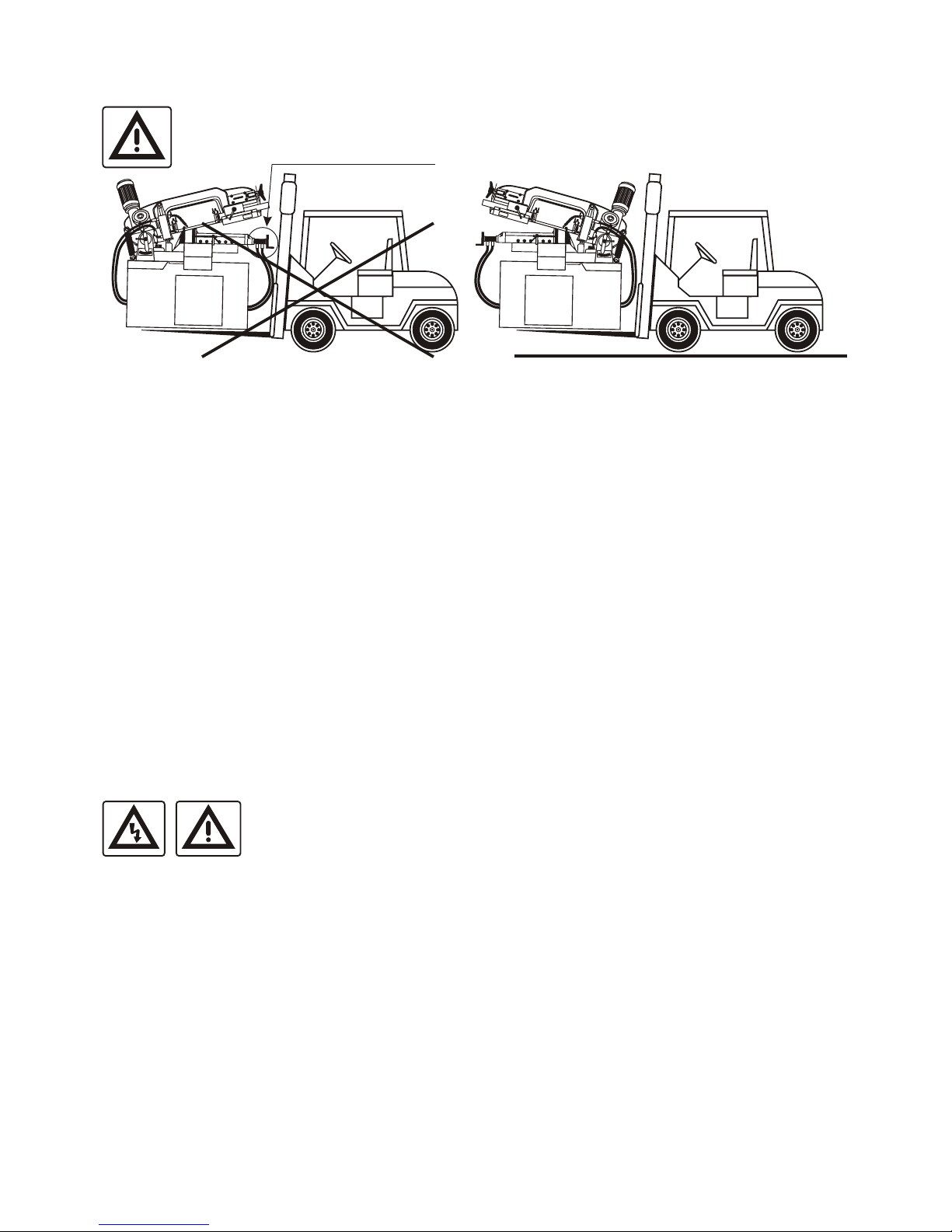
1. Transport and Storage
1.1. Surface Treatment
1.2. Packing
1.3. Dismantling/Repackaging
1.4. Disposal
2. Installation
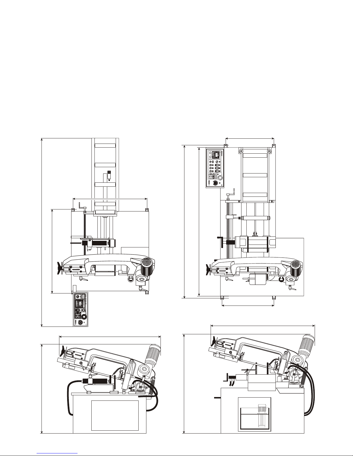
2.1. Space Requirements
2.2. Dismantling of Transport Beams and Machine Alignment
2.3. Machine Installation
2.4. Connection to Energy Supplies
3. Technical Data
4. Machine Description
4.1. ARG 220 D(F)-NC Automat
4.2. ARG 250 D(F)-NC Automat
4.3. ARG 250 C(F)-NC Automat
4.4. ARG 300 D(F)-NC Automat
4.5. ARG 300 C(F)-NC Automat
5. Description of Individual Units
5.1. Setting of Cutting Angle
5.2. Material clamping
5.2.1. Setting of Vice Clamping Force
5.2.2. Setting of Vice Side Clearance
5.2.3. Moving Viced Feed System
5.2.4. Setting of Feeding Speed of Moving Vice
5.2.5. Setting der Auxiliary Roller
5.2.6. Pressure Device for Bundle Cutting
5.3. Saw Blade Guide
5.3.1. Saw Blade Replacement, Tension and Setting
5.3.2. Guide Head Setting
5.4. Saw Blade Feed into Cutting Position
5.5. Setting of Band saw Head Strke Height
5.6. Hydraulic Unit
5.7. Cooling System
6. Description of Control Board and Setting of
VISION Control Unit
6.1. ARG 220 D(F)-NC Automat
6.2. ARG 250 D(F)-NC Automat,
ARG 300 D(F)-NC Automat
6.3. ARG 250 C(F)-NC Automat,
ARG 300 C(F)-NC Automat
7. Putting into Operation
7.1. ARG 220 D(F)-NC Automat - First Cut
7.2. ARG 250, 300 NC Automat - First Cut
Dear customer,,
Thank you for buying our product. Please read through this instruction carefully. It will help you understand the machine
and operate it smoothly.
© 2007 Al rights, particularly the right to make copies of, to distribute and translate this instruction manual, are
reserved. No part of this instruction manual may be reproduced in any form (printing, microfilm or others) or stored,
processed, copied or distributed by using electronic systems without permission of PILOUS.