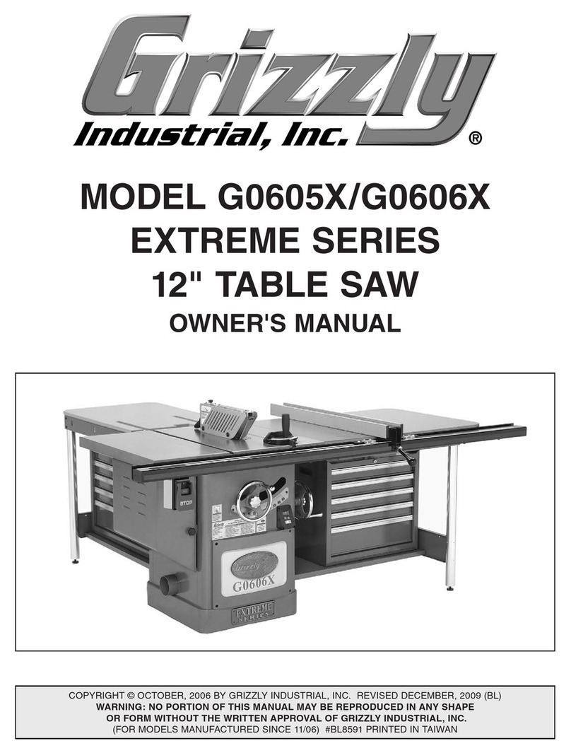
Grizzly G0588/G0591 User manual

12" SLIDING TABLE SAW
MODEL G0588/G0591
INSTRUCTION MANUAL
COPYRIGHT © MAY, 2005 BY GRIZZLY INDUSTRIAL, INC. REVISED NOVEMBER, 2005.
WARNING: NO PORTION OF THIS MANUAL MAY BE REPRODUCED IN ANY SHAPE
OR FORM WITHOUT THE WRITTEN APPROVAL OF GRIZZLY INDUSTRIAL, INC.
#EW7041 PRINTED IN TAIWAN

WARNING
Some dust created by power sanding, sawing, grind-
ing, drilling, and other construction activities contains
chemicals known to the State of California to cause
cancer, birth defects or other reproductive harm. Some
examples of these chemicals are:
• Lead from lead-based paints.
• Crystalline silica from bricks, cement, and
other masonry products.
• Arsenic and chromium from chemically treated
lumber.
Your risk from these exposures varies, depending on
how often you do this type of work. To reduce your
exposure to these chemicals: work in a well ventilated
area, and work with approved safety equipment, such
as those dust masks that are specially designed to fil-
ter out microscopic particles.

Table of Contents
INTRODUCTION ............................................................................................................................... 3
Foreword .................................................................................................................................... 3
Contact Info ................................................................................................................................ 3
Machine Data Sheet ................................................................................................................... 4
Identification ............................................................................................................................... 5
SECTION 1: SAFETY ....................................................................................................................... 7
Safety Instructions for Machinery ............................................................................................... 7
Additional Safety Instructions for Table Saws ........................................................................... 9
Preventing Kickback ................................................................................................................. 10
Protecting Yourself from Kickback ........................................................................................... 10
Glossary Of Terms ................................................................................................................... 11
SECTION 2: CIRCUIT REQUIREMENTS ...................................................................................... 12
220V Single-Phase .................................................................................................................. 12
220/440V 3-Phase ................................................................................................................... 13
Phase Converter ...................................................................................................................... 14
Grounding ................................................................................................................................. 14
Rewiring to 440V ...................................................................................................................... 14
SECTION 3: SET UP ...................................................................................................................... 16
Set Up Safety ........................................................................................................................... 16
Unpacking ................................................................................................................................ 16
Items Needed For Set Up ........................................................................................................ 16
Moving & Placing Base Unit ..................................................................................................... 17
Site Considerations .................................................................................................................. 17
Clean Up .................................................................................................................................. 18
Inventory ................................................................................................................................... 18
Hardware Recognition Chart .................................................................................................... 20
Extension Tables ...................................................................................................................... 21
Rip Fence and Scale ................................................................................................................ 22
Main Blade ............................................................................................................................... 24
Scoring Blade ........................................................................................................................... 25
Aligning Blades ........................................................................................................................ 26
Riving Knife Adjustment ........................................................................................................... 26
Sliding Table ............................................................................................................................ 28
Sliding Table Parallelism .......................................................................................................... 29
Crosscut Table ......................................................................................................................... 30
Crosscut Fence ........................................................................................................................ 30
Fence Scale Alignment ............................................................................................................ 31
Dust Collection ......................................................................................................................... 31
Power Cord .............................................................................................................................. 32
Test Run ................................................................................................................................... 32

SECTION 4: OPERATIONS ........................................................................................................... 33
Operation Safety ...................................................................................................................... 33
Operation Tips .......................................................................................................................... 33
Changing Blades ...................................................................................................................... 34
Rip Cutting ............................................................................................................................... 35
Crosscutting ............................................................................................................................. 37
Miter Cutting ............................................................................................................................. 39
SECTION 5: ACCESSORIES ......................................................................................................... 40
SECTION 6: MAINTENANCE ........................................................................................................ 43
Schedule .................................................................................................................................. 43
Cleaning ................................................................................................................................... 43
Unpainted Cast Iron ................................................................................................................. 43
Lubrication ................................................................................................................................ 44
SECTION 7: SERVICE ................................................................................................................... 45
About Service ........................................................................................................................... 45
Replacing Belts ........................................................................................................................ 45
Blade Tilt .................................................................................................................................. 47
Squaring Crosscut Fence to Blade .......................................................................................... 48
Electrical ................................................................................................................................... 49
Troubleshooting ........................................................................................................................ 50
SECTION 8: PARTS ....................................................................................................................... 52
Main Body ................................................................................................................................ 53
Extension Tables ...................................................................................................................... 55
Sliding Table ............................................................................................................................ 57
Crosscut Table ......................................................................................................................... 59
Crosscut Fence ........................................................................................................................ 61
Rip Fence ................................................................................................................................. 63
Trunnion Assembly .................................................................................................................. 65
Motor Assembly ....................................................................................................................... 67
Arbor Assembly ........................................................................................................................ 69
WARRANTY AND RETURNS ........................................................................................................ 70

G0588/G0591 12" Sliding Table Saws -3-
If you have any comments regarding this manual,
please write to us at the address below:
Grizzly Industrial, Inc.
C/O Technical Documentation
P.O. Box 2069
Bellingham, WA 98227-2069
We stand behind our machines. If you have any
service questions or parts requests, please call or
write us at the location listed below.
Grizzly Industrial, Inc.
1203 Lycoming Mall Circle
Muncy, PA 17756
Phone: (570) 546-9663
Fax: (800) 438-5901
E-Mail: [email protected]
Web Site: http://www.grizzly.com
Foreword
INTRODUCTION
Contact Info
We are proud to offer the Model G0588/G0591
12" Sliding Table Saws. These machines are part
of a growing Grizzly family of fine woodworking
machinery. When used according to the guide-
lines set forth in this manual, you can expect
years of trouble-free, enjoyable operation and
proof of Grizzly’s commitment to customer satis-
faction.
We are pleased to provide this manual with the
Model G0588/G0591. It was written to guide you
through assembly, review safety considerations,
and cover general operating procedures. It repre-
sents our effort to produce the best documenta-
tion possible.
The specifications, drawings, and photographs
illustrated in this manual represent the Model
G0588/G0591 as supplied when the manual was
prepared. However, owing to Grizzly’s policy
of continuous improvement, changes may be
made at any time with no obligation on the part
of Grizzly. For your convenience, we always
keep current Grizzly manuals available on our
website at www.grizzly.com. Any updates to
your machine will be reflected in these manuals
as soon as they are complete. Visit our site often
to check for the latest updates to this manual!

-4- G0588/G0591 12" Sliding Table Saws
Overall Dimensions:
Overall Size .........................140" W (192" w/Cross Slide Fence Extended) x 126" D (270" w/Sliding Table Extended) x 48" H
Table Height ............................................................................................................................................................................ 36"
Table Size (w/Extension Wings) ............................................................................................................................65" W x 59" D
Sliding Table Size ........................................................................................................................................... 13¾" W x 118" D
Machine Net Weight .......................................................................................................................................................1140 lbs.
Machine Shipping Weight ..............................................................................................................................................1430 lbs.
Crate 1 Size ........................................................................................................................................893⁄8" W x 40½" D x 44" H
Crate 2 Size ......................................................................................................................................1313⁄8" W x 17" D x 117⁄8" H
Base Footprint (w/Extension Leg) ..........................................................................................................................79" W x 74" D
Capacities:
Main Blade Diameter ................................................................................................................................................12" (305mm)
Scoring Blade Diameter ............................................................................................................................................31⁄8" (80mm)
Maximum Depth of Cut at 90˚ ..............................................................................................................................................311⁄16"
Maximum Depth of Cut at 45˚ ................................................................................................................................................ 23⁄4"
Blade Tilt ............................................................................................................................................................................. 0–45˚
Table w/Rip Fence Max Cutting Width ................................................................................................................................... 48"
Sliding Table w/Cross Fence Max Cut Width ....................................................................................................................... 126"
Sliding Table w/Cross Fence Max Cut Length ...................................................................................................................... 118"
Construction:
Sliding Table ................................................................................................................................................................ Aluminum
Machine Frame .................................................................................................................................................................... Steel
Fence ............................................................................................................................................................Extruded Aluminum
Rails ..................................................................................................................................................................... Chromed Steel
Trunnions .......................................................................................................................................................................Cast Iron
Motor:
G0588 Motor ............................................................................................71⁄2 HP, 220/440V (Prewired 220V), 20/10A, 3-Phase
G0591 Motor ..............................................................................................................................5 HP, 220V, 22A, Single-Phase
Motor RPM .................................................................................................................................................................. 3450 RPM
Main Blade Arbor ...................................................................................................................................................................... 1"
Main Blade Arbor Speed ............................................................................................................................................. 4900 RPM
Scoring Blade Arbor ........................................................................................................................................................... 20mm
Scoring Arbor Speed ................................................................................................................................................... 9000 RPM
Ball Bearings .............................................................................................................................................Shielded & Lubricated
Power Transfer ..............................................................................................................................................................Belt Drive
Switch ..........................................................................................................................Magnetic w/Thermal Overload Protection
Features:
...................................................................................................................................................... Blade Guard w/2½" Dust Port
......................................................................................................................................................................... 5" Main Dust Port
...................................................................................................................................................... Adjustable Scoring Knife Kerf
................................................................................................................................................................ Adjustable Riving Knife
............................................................................................................................ Micro Adjustable, Single Lever Locking Fence
MODEL G0588/G0591 12" Sliding Table Saws
Customer Service #: (570) 546-9663 • To Order Call: (800) 523-4777 • Fax #: (800) 438-5901
MACHINE DATA
SHEET
Specifications, while deemed accurate, are not guaranteed.

G0588/G0591 12" Sliding Table Saws -5-
Figure 1. Main view of machine features and controls.
C
H
I
Identification
A. Crosscut Table: Provides a wide, stable
platform for supporting full-size panels during
crosscutting operations.
B. Flip Stops: Used for quick measurements for
crosscutting.
C. Crosscut Fence: Used during crosscutting
operations. Features a scale and multiple
flip-style stop blocks for precise, repeatable
crosscutting operations.
D. Blade Guard: Fully-adjustable blade guard
maintains maximum protection around the
saw blade and a 2½" dust port effectively
extracts dust from the cutting operation.
E. Rip Fence: Fully adjustable with micro-adjust-
ment knob for precision adjustments. Fence
face can be positioned for standard cutting
operations, or in the lower position for blade
guard clearance during narrow ripping opera-
tions.
F. Sliding Table: Conveniently glides the
workpiece through the blade with effortless
precision and ease.
G. EMERGENCY STOP Button: Turns the
motor OFF when pushed.
H. Power ON/OFF Buttons: Turns the main
and scoring blades ON or OFF.
I. Blade Angle Handwheel: Adjusts the angle
of the saw blades.
A
F
DE
B
G

-6- G0588/G0591 12" Sliding Table Saws
P. Riving Knife: Maintains kerf opening during
cutting operations. This function is crucial to
preventing kickback caused by the kerf clos-
ing behind the blade.
Q. Main Blade (Not Included): Performs the
cutting operations.
R. Scoring Blade (Not Included): Small cut-
ting blade that rotates opposite the main
saw blade. The blade scores the workpiece
before the actual cutting operation is per-
formed preventing tear-out in laminate mate-
rials. The scoring blade is adjustable left and
right, up and down, and in thickness of kerf.
S. Scoring Blade Vertical Adjustment Socket:
Internal cap screw adjusts the height of the
scoring blade.
T. Scoring Blade Horizontal Adjustment
Socket: Internal cap screw adjusts the hori-
zontal position of the scoring blade in relation
to the main blade.
U. Scoring Blade Lock Socket: Locks the
scoring blade adjustments.
V. Lower Blade Guard: Prevents accidental
contact with the blade when the table is at its
full extension.
Figure 2. Fence controls. Figure 3. Blades.
J. Rip Fence Body Lock Lever: Secures the
fence body in position along the fence rail.
K. Rip Fence Scale: Allows precise measure-
ment of rip cutting operations.
L. Rip Fence Lock Handle: Secures the fence
face on its forward/backward slide track.
M. Micro-Adjust Knob: Precisely adjusts the
fence.
N. Fence Face: The surface that the workpiece
slides along.
O. Fence Body: Guides the fence along the rail
and supports the fence face.
J
N
K
MP
R
L
O
Q
V
T
U
S

G0588/G0591 12" Sliding Table Saws -7-
4. ALWAYS USE HEARING PROTECTION
WHEN OPERATING MACHINERY.
Machinery noise can cause permanent
hearing damage.
5. WEAR PROPER APPAREL. DO NOT
wear loose clothing, gloves, neckties, rings,
or jewelry which may get caught in moving
parts. Wear protective hair covering to con-
tain long hair and wear non-slip footwear.
6. NEVER OPERATE MACHINERY WHEN
TIRED, OR UNDER THE INFLUENCE OF
DRUGS OR ALCOHOL. Be mentally alert
at all times when running machinery.
1. READ THROUGH THE ENTIRE MANUAL
BEFORE STARTING MACHINERY.
Machinery presents serious injury hazards
to untrained users.
2. ALWAYS USE ANSI APPROVED
SAFETY GLASSES WHEN OPERATING
MACHINERY. Everyday eyeglasses only
have impact resistant lenses, they are
NOT safety glasses.
3. ALWAYS WEAR AN ANSI APPROVED
RESPIRATOR WHEN OPERATING
MACHINERY THAT PRODUCES DUST.
Wood dust is a carcinogen and can cause
cancer and severe respiratory illnesses.
For Your Own Safety, Read Instruction
Manual Before Operating this Machine
The purpose of safety symbols is to attract your attention to possible hazardous conditions. This
manual uses a series of symbols and signal words which are intended to convey the level of
importance of the safety messages. The progression of symbols is described below. Remember
that safety messages by themselves do not eliminate danger and are not a substitute for proper
accident prevention measures.
Safety Instructions for Machinery
SECTION 1: SAFETY
NOTICE
Indicates a potentially hazardous situation which, if not avoided,
MAY result in minor or moderate injury. It may also be used to alert
against unsafe practices.
Indicates a potentially hazardous situation which, if not avoided,
COULD result in death or serious injury.
Indicates an imminently hazardous situation which, if not avoided,
WILL result in death or serious injury.
This symbol is used to alert the user to useful information about
proper operation of the machine.

-8- G0588/G0591 12" Sliding Table Saws
7. ONLY ALLOW TRAINED AND PROP-
ERLY SUPERVISED PERSONNEL TO
OPERATE MACHINERY. Make sure
operation instructions are safe and clearly
understood.
8. KEEP CHILDREN AND VISITORS AWAY.
Keep all children and visitors a safe dis-
tance from the work area.
9. MAKE WORKSHOP CHILD PROOF. Use
padlocks, master switches, and remove
start switch keys.
10. NEVER LEAVE WHEN MACHINE IS
RUNNING. Turn power OFF and allow all
moving parts to come to a complete stop
before leaving machine unattended.
11. DO NOT USE IN DANGEROUS
ENVIRONMENTS. DO NOT use machin-
ery in damp, wet locations, or where any
flammable or noxious fumes may exist.
12. KEEP WORK AREA CLEAN AND WELL
LIT. Clutter and dark shadows may cause
accidents.
13. USE A GROUNDED EXTENSION CORD
RATED FOR THE MACHINE AMPERAGE.
Undersized cords overheat and lose power.
Replace extension cords if they become
damaged. DO NOT use extension cords
for 220V machinery.
14.
ALWAYS DISCONNECT FROM POWER
SOURCE BEFORE SERVICING
MACHINERY. Make sure switch is in
OFF
position before reconnecting.
15. MAINTAIN MACHINERY WITH CARE.
Keep blades sharp and clean for best and
safest performance. Follow instructions for
lubricating and changing accessories.
16. MAKE SURE GUARDS ARE IN PLACE
AND WORK CORRECTLY BEFORE
USING MACHINERY.
Safety Instructions for Machinery
17. REMOVE ADJUSTING KEYS AND
WRENCHES. Make a habit of checking for
keys and adjusting wrenches before turn-
ing machinery ON.
18. CHECK FOR DAMAGED PARTS
BEFORE USING MACHINERY. Check
for binding and alignment of parts, broken
parts, part mounting, loose bolts, and any
other conditions that may affect machine
operation. Repair or replace damaged
parts.
19. USE RECOMMENDED ACCESSORIES.
Refer to the instruction manual for recom-
mended accessories. The use of improper
accessories may cause risk of injury.
20. DO NOT FORCE MACHINERY. Work at
the speed for which the machine or acces-
sory was designed.
21. SECURE WORKPIECE. Use clamps or
a vise to hold the workpiece when practi-
cal. A secured workpiece protects your
hands and frees both hands to operate the
machine.
22. DO NOT OVERREACH. Keep proper foot-
ing and balance at all times.
23. MANY MACHINES WILL EJECT THE
WORKPIECE TOWARD THE OPERATOR.
Know and avoid conditions that cause the
workpiece to "kickback."
24. ALWAYS LOCK MOBILE BASES
(IF USED) BEFORE OPERATING
MACHINERY.
25. BE AWARE THAT CERTAIN WOODS
MAY CAUSE AN ALLERGIC REACTION
in people and animals, especially when
exposed to fine dust. Make sure you
know what type of wood dust you will be
exposed to and always wear an approved
respirator.

G0588/G0591 12" Sliding Table Saws -9-
Safety Instructions for Sliding Table Saws
7. RIP FENCE USAGE. When using the
crosscut fence, the workpiece should never
contact the rip fence while the saw blade is
cutting.
8. STALLED BLADE. Turn the saw OFF
before "freeing" a stalled saw blade.
9. AWKWARD OPERATIONS. Avoid awk-
ward operations and hand positions where
a sudden slip could cause your hand to
move into the spinning saw blade.
10. BLADE HEIGHT. Always adjust the blade
to the proper height above the workpiece.
11. DAMAGED SAW BLADES. Never use
blades that have been dropped or dam-
aged. A damaged blade could lose teeth
while turning, causing injury or death.
12. RIVING KNIFE ALIGNMENT. Only oper-
ate the saw if the riving knife is aligned with
the main blade to prevent kickback.
13. EXPERIENCING DIFFICULTIES. If at any
time you are experiencing difficulties per-
forming the intended operation, stop using
the machine! Contact Tech Support at
(570) 546-9663.
1. SAFETY ACCESSORIES. Always use the
blade guard and riving knife on all ''through-
sawing'' operations. Through-sawing oper-
ations are those when the blade cuts com-
pletely through the workpiece.
2. KICKBACK. Kickback is defined as high
speed expulsion of stock from the table
saw toward the operator. Until you have a
clear understanding of kickback and how it
occurs, DO NOT operate this table saw!
3. WORKPIECE CONTROL. Make sure the
workpiece is placed in a stable position on
the table and is either supported by the rip
fence or the crosscut table during cutting
operations.
4. PUSH STICK. Always use a push stick
when ripping narrow stock.
5. OPERATOR POSITION. Never stand or
have any part of your body directly in-line
with the cutting path of the saw blade.
6. REACHING OVER SAW BLADE. Never
reach behind or over the blade with either
hand while the saw is running. If kick-
back occurs while reaching over the blade,
hands or arms could be pulled into the
spinning saw blade.
No list of safety guidelines can be complete.
Every shop environment is different. Always
consider safety first, as it applies to your
individual working conditions. Use this and
other machinery with caution and respect.
Failure to do so could result in serious per-
sonal injury, damage to equipment, or poor
work results.
Like all machines there is danger associat-
ed with the Model G0588/G0591. Accidents
are frequently caused by lack of familiarity
or failure to pay attention. Use this machine
with respect and caution to lessen the pos-
sibility of operator injury. If normal safety
precautions are overlooked or ignored, seri-
ous personal injury may occur.

-10- G0588/G0591 12" Sliding Table Saws
Below are tips to reduce the likelihood of
kickback:
• Never attempt freehand cuts. If the workpiece
is not fed perfectly parallel with the blade, a
kickback will likely occur. Always use the
rip fence or crosscut fence to support the
workpiece.
• Make sure the riving knife is always aligned
with the blade. A misaligned riving knife can
cause the workpiece to bind or stop the flow
of the cut, resulting in an increased chance
of kickback. If you think that your riving knife
is not aligned with the blade, check it imme-
diately!
• Ensure that your table slides parallel with the
blade; otherwise, the chances of kickback
are extreme. Take the time to check and
adjust the sliding table.
• Use the riving knife whenever performing a
through cut. The riving knife helps maintain
the kerf in the workpiece after it is cut, there-
fore, reducing the chance of kickback.
• Keep the blade guard installed and in good
working order. Only remove it when perform-
ing non-through cuts and immediately re-
install the blade guard when finished with the
non-through cut.
Even if you know how to prevent kickback,
it may still happen. Here are some tips to
reduce the likelihood of injury if kickback
DOES occur:
• Never, for any reason, place your hand
behind the blade. Should kickback occur,
your hand will be pulled into the blade.
• Stand to the side of the blade during every
cut. If a kickback does occur, the thrown
workpiece usually travels directly in front of
the blade.
• Always wear safety glasses or a face shield.
In the event of a kickback, your eyes and
face are the most vulnerable part of your
body.
• Use a pushstick to keep your hands farther
away from the moving blade. If a kickback
occurs, the push stick will most likely take
the damage that your hand would have
received.
Protecting Yourself
from Kickback
Statistics prove that most common acci-
dents among table saw users can be linked
to kickback. Kickback is typically defined
as the high-speed expulsion of stock from
the table saw toward its operator. In addi-
tion to the danger of the operator or oth-
ers in the area being struck by the flying
stock, the operator’s hands can be pulled
into the blade during the kickback.
Preventing Kickback
• Make multiple, shallow passes when per-
forming a non-through cut. Making a deep
non-through cut will greatly increase the
chance of kickback.
• Feed cuts through to completion. Anytime
you stop feeding a workpiece that is in the
middle of a cut, the chance of binding, result-
ing in kickback, is greatly increased.

G0588/G0591 12" Sliding Table Saws -11-
The following is a list of common definitions, terms and phrases used throughout this manual as they relate
to this table saw and woodworking in general. Become familiar with these terms for assembling, adjusting
or operating this machine. Your safety is VERY important to us at Grizzly!
Arbor: A metal shaft extending from the drive
mechanism that is the mounting location for
the saw blade.
Bevel Edge Cut: Tilting the arbor and saw blade
to an angle between 0˚ and 45˚ to cut a bev-
eled edge onto a workpiece.
Blade Guard: Metal or plastic safety device that
mounts over the saw blade. Its function is to
prevent the operator from coming into contact
with the saw blade.
Crosscut: Cutting operation in which the cross-
cut fence is used to cut across the shortest
width of the workpiece.
Dado Blade: Blade or set of blades that are used
to cut grooves and rabbets.
Dado Cut: Cutting operation that uses a dado
blade to cut a flat bottomed groove into the
face of the workpiece.
Featherboard: Safety device used to keep the
workpiece against the rip fence and against the
table surface.
Kerf: The resulting cut or gap in the workpiece
after the saw blade passes through during a
cutting operation.
Kickback: An event in which the workpiece is
propelled back towards the operator at a high
rate of speed.
Parallel: Being an equal distance apart at every
point along two given lines or planes (i.e. the
rip fence face is parallel to the face of the saw
blade).
Non-Through Cut: A sawing operation that
requires the removal of the blade guard and riv-
ing knife. Dado and rabbet cuts are considered
Non-Through Cuts because the blade does
not protrude above the top face of the wood
stock. Deep Non-Through Cuts must be made
with multiple, light passes to reduce chance
of kickback. Always remember to re-install the
blade guard and riving knife after performing a
non-through cut.
Perpendicular: Lines or planes that intersect
and form right angles (i.e. the blade is perpen-
dicular to the table surface).
Push Stick: Safety device used to push the
workpiece through a cutting operation. Used
most often when rip cutting thin workpieces.
Rabbet: Cutting operation that creates an L-
shaped channel along the edge of the
workpiece.
Riving Knife (Splitter): Metal plate located
behind the blade. It maintains the kerf opening
in the wood when performing a cutting opera-
tion.
Straightedge: A tool used to check the flatness,
parallelism, or consistency of a surface(s).
Through Cut: A sawing operation in which the
workpiece is completely sawn through.
Rip Cut: Cutting operation in which the rip fence
is used to cut across the widest width of the
workpiece.
Glossary of Terms

-12- G0588/G0591 12" Sliding Table Saws
Serious personal injury could occur if you
connect the machine to the power source
before you have completed the set up pro-
cess. DO NOT connect the machine to the
power source until instructed to do so.
220V Single-Phase
Amperage Draw
The 5 HP motor on the Model G0591 will draw the
following amps:
Motor Draw at 220V ..............................22 Amps
Minimum Circuit Requirements
Only connect your machine to a circuit that meets
the requirements below. Check to see if the wires
and circuit breaker in your circuit are capable of
handling the amperage draw from your machine,
as well as any other machines that could be
operating on the same circuit. If you are unsure,
consult a qualified electrician.
Minimum Circuit Requirement .................25 Amp
Minimum Cord Requirements
Use the following type of cord to connect your
machine to power (a cord is not provided):
Cord ............................................................3 wire
Gauge .................................................. 10 Gauge
Extension Cords
We do not recommend the use of extension cords
on 220V equipment. Instead, arrange the place-
ment of your equipment and the installed wiring to
eliminate the need for extension cords.
If you find it absolutely necessary to use an exten-
sion cord at 220V with your machine, check with
a qualified electrician for the correct sizing, type,
and maximum possible length for your needs.
SECTION 2: CIRCUIT REQUIREMENTS
Electrocution or fire could
result if this machine is
not grounded correctly
or if your electrical con-
figuration does not com-
ply with local and state
codes. Ensure compliance
by checking with a quali-
fied electrician!
Figure 4. NEMA L6-30 plug and receptacle.
Connection Type
Recommended Plug/Receptacle ....NEMA L6-30
Another option for increased safety is to hardwire
your machine directly to the circuit breaker and
install a locking shut-off lever near the machine
as a way to quickly disconnect the power and
prevent accidental starting (see Figure 5).
Grounding
In the event of an electrical short, grounding
reduces the risk of electric shock. The ground-
ing wire in the cord must be properly connected
to the grounding prong on the plug; likewise, the
outlet must be properly installed and grounded.
All electrical connections must be made in accor-
dance with local codes and ordinances.

G0588/G0591 12" Sliding Table Saws -13-
A fire may occur if your particular electrical
configuration does not comply with local and
state codes. The best way to ensure compli-
ance is to check with your local municipality
or a qualified electrician.
Serious personal injury could occur if you
connect your machine to the power source
before you have completed the set up pro-
cess. DO NOT connect the machine to the
power source until instructed to do so.
Wiring
The Model G0588 is prewired for 220V 3-phase
operation. If 440 voltage is required, rewire the
machine according to the instructions on Page 14
and follow the circuit requirements on this page.
Amperage Draw
The Model G0588 has a 71⁄2 HP main motor that
will draw the following amps:
Motor Draw at 220V ..............................20 Amps
Motor Draw at 440V .............................. 10 Amps
Minimum Circuit Requirements
Only connect your machine to a circuit that meets
the requirements below. Check to see if the wires
and circuit breaker in your circuit are capable of
handling the amperage draw from your machine,
as well as any other machines that could be
operating on the same circuit. If you are unsure,
consult a qualified electrician.
220V Circuit .............................................25 Amp
440V Circuit .............................................15 Amp
Minimum Cord Requirements
Use the following type of cord to connect your
machine to power (a cord is not provided):
Cord ............................................................4 wire
Gauge .................................................. 10 Gauge
220/440V 3-Phase
Figure 5. A power disconnect is preferable to
high current plugs and receptacles.
Connection Type
We recommend hardwiring 3-phase machines
directly to the circuit breaker and installing a lock-
ing shut-off lever near the machine as a way to
quickly disconnect the power and prevent acci-
dental starting (see Figure 5).

-14- G0588/G0591 12" Sliding Table Saws
In the event of an electrical short, grounding
reduces the risk of electric shock. The ground-
ing wire in the cord must be properly connected
to the grounding prong on the plug; likewise, the
outlet must be properly installed and grounded.
All electrical connections must be made in accor-
dance with local codes and ordinances.
Improper connections of the electrical-grounding
conductor increases the risk of electric shock.
Check with a qualified electrician or one of our
service personnel if you do not understand
the grounding instructions, or if you doubt the
machine is properly grounded.
Grounding
Electrocution or fire could
result if this machine is
not grounded correctly
or if your electrical con-
figuration does not com-
ply with local and state
codes. Ensure compliance
by checking with a quali-
fied electrician!
The Model G0588 can be rewired for 440V oper-
ation. This rewiring job consists of disconnecting
the saw from the power source, replacing the
magnetic switch, and rewiring the motor.
The necessary magnetic switch for this proce-
dure can be purchased by calling our Customer
Service number at (800) 523-4777.
This procedure takes moderate electrical skill
and the rewiring job must be inspected by a quali-
fied electrician before the saw is connected to the
power source.
To rewire the Model G0588 for 440V opera-
tion:
1. Disconnect the saw from the power
source!
2. Remove the control panel cover plate shown
in Figure 6.
Rewiring to 440V
Figure 6. Control panel cover plate.
When using a phase converter, the power from
the manufactured power leg (sometimes called
the wild wire) can fluctuate. Connect the manufac-
tured power leg to the S terminal to prevent dam-
age to the electrical controls. The wire from the S
terminal can handle some fluctuation because it
goes directly to the motor. The power going to the
R and T terminals goes to the electrical controls
and must be consistent to prevent damage. See
the instruction manual included with the phase
converter for more information.
Phase Converter

G0588/G0591 12" Sliding Table Saws -15-
3. Remove the control panel surrounding plate
and the cover.
4. Replace the 220V magnetic switch (Figure
7) with the 440V magnetic switch. Set the
dial on the new overload relay to 11A.
Note: The magnetic switch consists of the
magnetic contactor and the overload relay.
7. Rewire the motor per the diagram on the
inside of the motor wiring cover.
Overload
Relay Dial
Overload
Relay
Figure 7. Magnetic switch.
6. Open the motor cabinet door and remove the
motor wiring cover (see Figure 8).
Figure 8. Motor location.
Magnetic
Contactor
5. Replace the control panel cover, surrounding
plate, and the cover plate.
Motor Wiring
Cover

-16- G0588/G0591 12" Sliding Table Saws
Wear safety glasses during
the entire set up process!
Set Up Safety
SECTION 3: SET UP
The Model G0588/G0591
is a heavy machine with
a shipping weight over
1400 lbs. Serious per-
sonal injury may occur if
safe moving methods are
not followed. To be safe,
get assistance and use
power equipment when
moving the crate and
removing the machine
from the crate.
Unsupervised children and
visitors inside your shop
could cause serious per-
sonal injury to themselves.
Lock all entrances to the
shop when you are away and
DO NOT allow unsupervised
children or visitors in your
shop at any time!
This machine presents
serious injury hazards
to untrained users. Read
through this entire manu-
al to become familiar with
the controls and operations
before starting the machine!
The following items are needed to complete the
set up, but are not included with your machine:
Description Qty
• Safety Glasses (for each person) .............. 1
• Power Lifting Equipment ............................ 1
• Lifting Straps (1500 lb capacity) ................. 2
• An Assistant ............................................... 1
• Main Blade 12" (305mm) ........................... 1
• Scoring Blade 3" (80mm) ........................... 1
• Phillips Head Screwdriver .......................... 1
• Dial Indicator, or an Adjustable Square
and Feeler Gauges .................................... 1
• Felt Tip Pen ................................................ 1
• Right Angle Square .................................... 1
• Dust Collection System .............................. 1
• 5" Dust Hose and Hose Clamps ................ 1
• 2½" Dust Hose and Hose Clamps ............. 1
• Power Cord (length as needed) ................. 1
• Power Disconnect Box ............................... 1
Items Needed for
Set Up
The Model G0588/G0591 was carefully packed
when it left our warehouse. If you discover the
machine is damaged after you have signed
for delivery, please immediately call Customer
Service at (570) 546-9663 for advice.
Save the containers and all packing materials for
possible inspection by the carrier or its agent.
Otherwise, filing a freight claim can be difficult.
When you are completely satisfied with the con-
dition of your shipment, you should inventory the
contents.
Unpacking

G0588/G0591 12" Sliding Table Saws -17-
Figure 10. Working clearances.
Floor Load
The G0588/G0591 weighs 1140 lbs. and has a
base footprint of 79" W x 74" D. Most commercial
floors are suitable for this machine. Residential
floors may require additional reinforcement to
support the machine and operator.
Working Clearances
Consider existing and anticipated needs, size of
material to be processed through your machine,
and space for auxiliary stands, work tables or
other machinery when establishing a location for
your saw. See Figure 10 for the minimum work-
ing clearances of the Model G0588/G0591.
Site Considerations
Moving & Placing
Base Unit
The Model G0588/G0591
is a heavy machine with
a shipping weight over
1400 lbs. Serious per-
sonal injury may occur if
safe moving methods are
not followed. To be safe,
get assistance and use
power equipment when
moving the crate and
removing the machine
from the crate.
To remove the saw base unit from the crate
pallet:
1. Remove the top of the crate and position the
forklift forks together and directly above the
saw.
2. Place two lifting straps with hooks on the
ends over the forks and slide the hooks into
the points shown in Figure 9.
Figure 9. Lifting the saw base unit.
3. Lift the saw base unit and move it to your
predetermined location.
DO NOT lift the table saw any higher than
necessary to clear the floor. Serious per-
sonal injury and damage to the machine
may occur if safe moving methods are not
followed.
Use lifting straps with a minimum of 1500
lbs. lifting capacity. If the lifting strap breaks,
serious personal injury may occur.

-18- G0588/G0591 12" Sliding Table Saws
Figure 11. Extension table components.
BC
D
Inventory
After all the parts have been removed from the
two boxes, you should have the following items:
Crate 1 .......................................................... Qty
A. Saw Base Unit (Not Shown) ...................... 1
B. Large Extension Wing ................................ 1
C. Small Extension Wing ................................ 1
D. Support Leg ................................................ 1
E. Rip Fence Round Rail w/M12 Studs,
Washers, and Nuts ..................................... 1
F. Square Tube w/Scale ................................. 1
G. Rip Fence Body .......................................... 1
H. Rip Fence Lock Handle .............................. 1
I. Aluminium Rip Fence ................................. 1
Figure 12. Rip fence components.
E
F
G
H
The unpainted surfaces are coated with a waxy
oil to protect them from corrosion during ship-
ment. Remove this protective coating with a sol-
vent cleaner or citrus-based degreaser such as
Grizzly’s G7895 Degreaser. To clean thoroughly,
some parts may need to be removed. For opti-
mum performance from your machine, make
sure you clean all moving parts or sliding
contact surfaces that are coated. Avoid chlo-
rine-based solvents, such as acetone or brake
parts cleaner, as they may damage painted sur-
faces should they come in contact. Always follow
the manufacturer’s instructions when using any
type of cleaning product.
Clean Up
Gasoline and petroleum
products have low flash
points and could cause
an explosion or fire if
used to clean machinery.
DO NOT use gasoline or
petroleum products to
clean the machinery.
Many of the solvents
commonly used to clean
machinery can be toxic
when inhaled or ingest-
ed. Lack of ventilation
while using these sol-
vents could cause seri-
ous personal health risks
or fire. Take precautions
from this hazard by only
using cleaning solvents
in a well ventilated area. I
This manual suits for next models
2
Table of contents
Other Grizzly Saw manuals

Grizzly
Grizzly G0715P User manual

Grizzly
Grizzly G0575 User manual

Grizzly
Grizzly G0622 User manual

Grizzly
Grizzly G0771 User manual

Grizzly
Grizzly G1060 User manual

Grizzly
Grizzly G0569 User manual

Grizzly
Grizzly G0580 Quick start guide

Grizzly
Grizzly G0901 User manual

Grizzly
Grizzly G0444 User manual

Grizzly
Grizzly G0817 User manual

Grizzly
Grizzly G1023S User manual

Grizzly
Grizzly G0478 User manual

Grizzly
Grizzly G9906 User manual

Grizzly
Grizzly G0566 User manual

Grizzly
Grizzly G9742 User manual

Grizzly
Grizzly G0478 User manual

Grizzly
Grizzly G3619 User manual

Grizzly
Grizzly G4030 User manual

Grizzly
Grizzly H3390 User manual

Grizzly
Grizzly G8122 User manual