Pilz PNOZ mc0p User manual

PNOZ mc0p
Operating Manual 21249-EN-03
}Configurable safety systems PNOZmulti

Preface
This document is a translation of the original document.
All rights to this documentation are reserved by Pilz GmbH & Co. KG. Copies may be made
for internal purposes. Suggestions and comments for improving this documentation will be
gratefully received.
Source code from third-party manufacturers or open source software has been used for
some components. The relevant licence information is available on the Internet on the Pilz
homepage.
Pilz®, PIT®, PMI®, PNOZ®, Primo®, PSEN®, PSS®, PVIS®, SafetyBUS p®,
SafetyEYE®, SafetyNET p®, the spirit of safety® are registered and protected trademarks
of Pilz GmbH & Co. KG in some countries.
SD means Secure Digital

Contents
Operating Manual PNOZ mc0p
21249-EN-03 3
Section 1 Introduction 4
1.1 Validity of documentation 4
1.2 Using the documentation 4
1.3 Definition of symbols 4
Section 2 Overview 6
2.1 Scope 6
2.2 Unit features 6
2.3 Front view 6
Section 3 Safety 7
3.1 Intended use 7
3.2 System requirements 7
3.3 Safety regulations 7
3.3.1 Use of qualified personnel 7
3.3.2 Warranty and liability 7
3.3.3 Disposal 8
3.3.4 For your safety 8
Section 4 Function description 9
4.1 Functions 9
4.2 Block diagram 9
Section 5 Installation 10
5.1 General installation guidelines 10
5.2 Dimensions in mm 10
5.3 Connect power supply to base unit and fieldbus module 10
Section 6 Commissioning 11
6.1 General wiring guidelines 11
6.2 Connection 11
6.3 Connection example 12
Section 7 Operation 13
Section 8 Technical details 14
Section 9 Order reference 16
9.1 Product 16
9.2 Accessories 16

Introduction
Operating Manual PNOZ mc0p
21249-EN-03 4
1 Introduction
1.1 Validity of documentation
This documentation is valid for the product PNOZ mc0p. It is valid until new documentation
is published.
This operating manual explains the function and operation, describes the installation and
provides guidelines on how to connect the product.
1.2 Using the documentation
This document is intended for instruction. Only install and commission the product if you
have read and understood this document. The document should be retained for future ref-
erence.
1.3 Definition of symbols
Information that is particularly important is identified as follows:
DANGER!
This warning must be heeded! It warns of a hazardous situation that poses
an immediate threat of serious injury and death and indicates preventive
measures that can be taken.
WARNING!
This warning must be heeded! It warns of a hazardous situation that could
lead to serious injury and death and indicates preventive measures that can
be taken.
CAUTION!
This refers to a hazard that can lead to a less serious or minor injury plus
material damage, and also provides information on preventive measures
that can be taken.
NOTICE
This describes a situation in which the product or devices could be dam-
aged and also provides information on preventive measures that can be
taken. It also highlights areas within the text that are of particular import-
ance.

Introduction
Operating Manual PNOZ mc0p
21249-EN-03 5
INFORMATION
This gives advice on applications and provides information on special fea-
tures.

Overview
Operating Manual PNOZ mc0p
21249-EN-03 6
2 Overview
2.1 Scope
}Expansion module PNOZ mc0p
}Jumper
2.2 Unit features
Using the product PNOZ mc0p:
Power supply used to supply voltage to the fieldbus modules PNOZ mc5p or PNOZ mc5.1p
LWL.
The product has the following features:
}Interface to connect the base unit and a fieldbus module
}Galvanic isolation
}Max. 1 fieldbus module (PNOZ mc5p or PNOZ mc5.1p LWL) can be connected
}Supply voltage 24 V DC
}Status indicators
}Please refer to the document "PNOZmulti System Expansion" for the PNOZmulti base
units that can be connected.
2.3 Front view
2

Safety
Operating Manual PNOZ mc0p
21249-EN-03 7
3 Safety
3.1 Intended use
The expansion module may only be connected to a base unit from the PNOZmulti system
(please refer to the document "PNOZmulti System Expansion" for details of the base units
that can be connected).
The configurable small control systems PNOZmulti are used for the safety-related interrup-
tion of safety circuits and are designed for use in:
}E-STOP equipment
}Safety circuits in accordance with VDE0113 Part 1 and EN60204-1
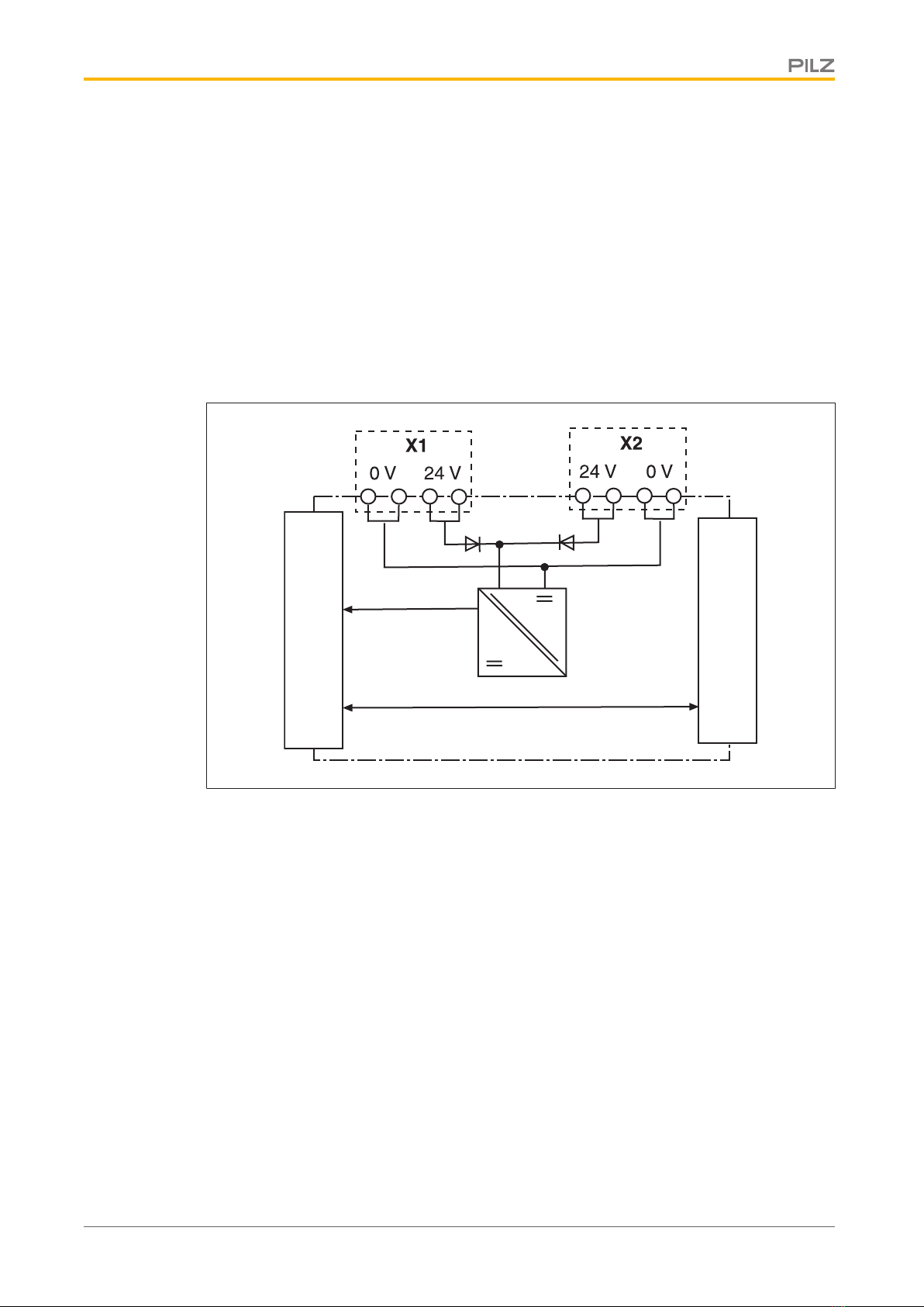
The module may only be used to supply voltage to the following fieldbus modules:
}PNOZ mc5p INTERBUS
}PNOZ mc5.1p INTERBUS LWL
3.2 System requirements
Please refer to the "Product Modifications PNOZmulti" document in the "Version overview"
section for details of which versions of the base unit and PNOZmulti Configurator can be
used for this product.
3.3 Safety regulations
3.3.1 Use of qualified personnel
The products may only be assembled, installed, programmed, commissioned, operated,
maintained and decommissioned by competent persons.
A competent person is someone who, because of their training, experience and current pro-
fessional activity, has the specialist knowledge required to test, assess and operate the
work equipment, devices, systems, plant and machinery in accordance with the general
standards and guidelines for safety technology.
It is the company’s responsibility only to employ personnel who:
}Are familiar with the basic regulations concerning health and safety / accident preven-
tion
}Have read and understood the information provided in this description under "Safety"
}And have a good knowledge of the generic and specialist standards applicable to the
specific application.
3.3.2 Warranty and liability
All claims to warranty and liability will be rendered invalid if
}The product was used contrary to the purpose for which it is intended
}Damage can be attributed to not having followed the guidelines in the manual
}Operating personnel are not suitably qualified
}Any type of modification has been made (e.g. exchanging components on the PCB
boards, soldering work etc.).

Safety
Operating Manual PNOZ mc0p
21249-EN-03 8
3.3.3 Disposal
}When decommissioning, please comply with local regulations regarding the disposal of
electronic devices (e.g. Electrical and Electronic Equipment Act).
3.3.4 For your safety
The unit meets all the necessary conditions for safe operation. However, you should always
ensure that the following safety requirements are met:
}This operating manual only describes the basic functions of the unit. The expanded
functions are described in the PNOZmulti Configurator's online help. Only use these
functions once you have read and understood the documentations.
}Do not open the housing or make any unauthorised modifications.
}Please make sure you shut down the supply voltage when performing maintenance
work (e.g. exchanging contactors).

Function description
Operating Manual PNOZ mc0p
21249-EN-03 9
4 Function description
4.1 Functions
The PNOZ mc0p power supply provides the fieldbus module with the necessary internal
supply voltage. This way the fieldbus module remains available even when the base unit is
switched off. The power supply is connected to the base unit and fieldbus module via jump-
ers. When the 24 VDC supply voltage is applied, the “POWER” LED is lit. The “BASE” LED
is lit when supply voltage is applied to the base unit.
4.2 Block diagram
Fieldbus module
Base module

Installation
Operating Manual PNOZ mc0p
21249-EN-03 10
5 Installation
5.1 General installation guidelines
}The control system should be installed in a control cabinet with a protection type of at
least IP54. Fit the control system to a horizontal mounting rail. The venting slots must
face upward and downward. Other mounting positions could destroy the control system.
}Use the notches on the rear of the unit to attach it to a mounting rail. Connect the con-
trol system to the mounting rail in an upright position, so that the earthing springs on the
control system are pressed on to the mounting rail.
}The ambient temperature of the PNOZmulti units in the control cabinet must not exceed
the figure stated in the technical details, otherwise air conditioning will be required.
}To comply with EMC requirements, the mounting rail must have a low impedance con-
nection to the control cabinet housing.
CAUTION!
Damage due to electrostatic discharge!
Electrostatic discharge can damage components. Ensure against discharge
before touching the product, e.g. by touching an earthed, conductive sur-
face or by wearing an earthed armband.
5.2 Dimensions in mm
94 (3.70")
22,5
(0.88")
114 (4.49")
5.3 Connect power supply to base unit and fieldbus module
Connect the modules as described in the operating instructions for the base units.
}Install the power supply to the left between the base unit and fieldbus module.

Commissioning
Operating Manual PNOZ mc0p
21249-EN-03 11
6 Commissioning
6.1 General wiring guidelines
Please note:
}The PNOZ mc0p can be supplied by a separate power supply (see Connection
example [ 12]). The power supply must meet the regulations for extra low voltages
with protective separation (SELV, PELV).
}The torque setting of the screws on the connection terminals is specified under Tech-
nical details [ 14].
}Use copper wiring with a temperature stability of 75 °C.
}Information given in the Technical details [ 14] must be followed.
6.2 Connection
Supply voltage AC DC
Supply voltage from Interbus
master only:
Connect the supply voltage to X1
or X2.
The fieldbus connection is main-
tained if the base unit is switched
off.
When the Interbus master is re-
started, the power supply to the
base unit must be reset.
24V + 24 V DC
0 V
24V
0V
0V
X1/X2
Supply voltage from Interbus
master and base unit:
Example:
Connect the supply voltage from
the base unit to X1.
Connect the supply voltage from
the Interbus master to X2.
The fieldbus connection is main-
tained if the base unit is switched
off.
When the Interbus master is re-
started, the fieldbus is available
immediately.
24V + 24 V DC
0 V
24V
0V
0V
X1
24V + 24 V DC
0 V
24V
0V
0V
X2

Commissioning
Operating Manual PNOZ mc0p
21249-EN-03 12
6.3 Connection example
Redundant power supply
I0
I1
I2
I3
I4
I5
I6
I7
I8
I9
I10
I11
I12
I13
I14
I15
I16
I17
I18
I19
A1
A1
A2
A2
CI+
CI-
CO-
CO+
T0
T1
T2
T3
O0
O1
O2
O3
OA0
24V
24V
0V
0V
13
14
23
24
L+
L-
PNOZ mc0p
24V
24V
0V
0V
PNOZ m1p
PNOZ mc5.1p
L+
L-
24V
24V
0V
0V

Operation
Operating Manual PNOZ mc0p
21249-EN-03 13
7 Operation
The unit is ready for operation when the "POWER" LED is lit continuously.
Status indicators:
}"POWER" is lit: Supply voltage is applied to PNOZ mc0p.
}"BASE" is lit: Supply voltage applied to base unit.

Technical details
Operating Manual PNOZ mc0p
21249-EN-03 14
8 Technical details
General
Approvals CCC, CE, EAC (Eurasian), cULus Listed
Electrical data
Supply voltage
for Module supply
Voltage 24,0 V
Kind DC
Voltage tolerance -15 %/+20 %
Output of external power supply (DC) 5,0 W
Residual ripple DC 5 %
Potential isolation yes
Status indicator LED
Times
Supply interruption before de-energisation 20 ms
Environmental data
Ambient temperature
In accordance with the standard EN 60068-2-14
Temperature range 0 - 55 °C
Storage temperature
In accordance with the standard EN 60068-2-1/-2
Temperature range -25 - 70 °C
Climatic suitability
In accordance with the standard EN 60068-2-30, EN 60068-2-78
Humidity 93 % r. h. at 40 °C
Condensation during operation Not permitted
EMC EN 61131-2
Vibration
In accordance with the standard EN 60068-2-6
Frequency 10,0 - 150,0 Hz
Acceleration 1g
Shock stress
In accordance with the standard EN 60068-2-27
Acceleration 15g
Duration 11 ms
Max. operating height above sea level 2000 m
Airgap creepage
In accordance with the standard EN 61131-2
Overvoltage category III
Pollution degree 2
Rated insulation voltage 30 V

Technical details
Operating Manual PNOZ mc0p
21249-EN-03 15
Environmental data
Protection type
In accordance with the standard EN 60529
Mounting area (e.g. control cabinet) IP54
Housing IP20
Terminals IP20
Potential isolation
Potential isolation between Module and system voltage
Type of potential isolation Functional insulation
Rated surge voltage 500 V
Mechanical data
Mounting position Horizontal on top hat rail
DIN rail
Top hat rail 35 x 7,5 EN 50022
Recess width 27 mm
Material
Bottom PPO UL 94 V0
Front ABS UL 94 V0
Connection type Spring-loaded terminal, screw terminal
Conductor cross section with screw terminals
1 core flexible 0,25 - 1,50 mm², 24 - 16 AWG
2 core with the same cross section, flexible without
crimp connectors or with TWIN crimp connectors 0,25 - 0,75 mm², 24 - 20 AWG
Torque setting with screw terminals 0,25 Nm
Stripping length with screw terminals 7 mm
Conductor cross section with spring-loaded terminals
1 core flexible without crimp connector 0,25 - 1,50 mm², 24 - 16 AWG
1 core flexible with crimp connector 0,25 - 0,75 mm², 24 - 20 AWG
Spring-loaded terminals: Terminal points per connec-
tion 1
Stripping length with spring-loaded terminals 9 mm
Dimensions
Height 94,0 mm
Width 22,5 mm
Depth 121,0 mm
Weight 125 g
Where standards are undated, the 2007-05 latest editions shall apply.

Order reference
Operating Manual PNOZ mc0p
21249-EN-03 16
9 Order reference
9.1 Product
Product type Features Order No.
PNOZ mc0p Expansion module, power supply for fieldbus modules 773 720
9.2 Accessories
Jumper
Product type Features Order No.
KOP-XE Jumper 774 639
Connection terminals
Product type Features Order No.
Set spring terminals 1 set of spring-loaded terminals 783 400
Set screw terminals 1 set of screw terminals 793 400

The Best of
German
Engineering
Partner of:
Support
Technical support is available from Pilz round the clock.
Americas
Brazil
+55 11 97569-2804
Canada
+1 888-315-PILZ (315-7459)
Mexico
+52 55 5572 1300
USA (toll-free)
+1 877-PILZUSA (745-9872)
Asia
China
+86 21 60880878-216
Japan
+81 45 471-2281
South Korea
+82 31 450 0680
Australia
+61 3 95446300
Europe
Austria
+43 1 7986263-0
Belgium, Luxembourg
+32 9 3217575
France
+33 3 88104000
Germany
+49 711 3409-444
Ireland
+353 21 4804983
Italy
+39 0362 1826711
Scandinavia
+45 74436332
Spain
+34 938497433
Switzerland
+41 62 88979-30
The Netherlands
+31 347 320477
Turkey
+90 216 5775552
United Kingdom
+44 1536 462203
You can reach our
international hotline on:
+49 711 3409-444
CMSE®, InduraNET p®, PAS4000®, PAScal®, PASconfig®, Pilz®, PIT®, PLID®, PMCprimo®, PMCprotego®, PMCtendo®, PMD®, PMI®, PNOZ®, Primo®, PSEN®, PSS®, PVIS®, SafetyBUS p®,
SafetyEYE®, SafetyNET p®, THE SPIRIT OF SAFETY®are registered and protected trademarks of Pilz GmbH & Co. KG in some countries. We would point out that product features may vary
from the details stated in this document, depending on the status at the time of publication and the scope of the equipment. We accept no responsibility for the validity, accuracy
and entirety of the text and graphics presented in this information. Please contact our Technical Support if you have any questions.
Pilz develops environmentally-friendly products using
ecological materials and energy-saving technologies.
Oces and production facilities are ecologically designed,
environmentally-aware and energy-saving. So Pilz oers
sustainability, plus the security of using energy-ecient
products and environmentally-friendly solutions.
Pilz GmbH & Co. KG
Felix-Wankel-Straße 2
73760 Ostfildern, Germany
Tel.: +49 711 3409-0
Fax: +49 711 3409-133
www.pilz.com
100XXXX-DE-0X
0-0-1-3-000, 2015-00 Printed in Germany
© Pilz GmbH & Co. KG, 2015
21249-EN-03, 2016-04 Printed in Germany
© Pilz GmbH & Co. KG, 2015
Front cover
Other manuals for PNOZ mc0p
1
Table of contents
Other Pilz Power Supply manuals