Pima 8841202 User manual

2
Figure 1
Figure 2
Figure 3

3
GENERAL DESCRIPTION
The DCM is a 2-way supervised transmitter that combines the Magnetic/Door Contact
(against opening doors and windows) with an additional universal input or shutter.
The DCM operates with PIMA’s 2-way wireless systems –FORCE and VISION series.
MAIN FEATURES
•Communication: 2-way
•Range: Up to 300 m (1,000 ft.) range line of sight
•Selective input termination: NO, NC, DEOL, Shutter
Magnet spacers Transmitter spacers
8170047 (x 10) 8170048 (x 10)
Option
Figure 4
Figure 5
Figure 6

4
•Selective input response: 10 / 500ms
•Tamper protection: Back + cover
LED INDICATION
•Upon successful learning: short flash sequence
•Normal operation: brief light upon transmission
•Low battery: short flash sequence during transmission
OPERATING MODE
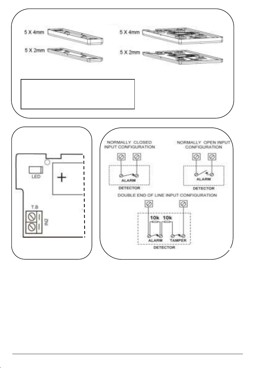
The DCM reports events from IN2 and from the magnetic reed switch. In normal
operation mode, an alarm is sent when the input or magnet are triggered. When
restored, it transmits a restoral message.
NOTE: If configured as Roller Shutter, the magnetic reed switch will not function.
INSTALLATION
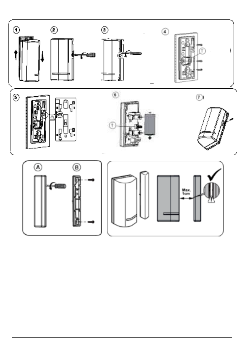
Step 1: Battery Insertion
1. Remove the front cover (Fig. 1-1 to 1-5).
2. Remove battery from the insulation material and reinsert it into the transmitter,
paying attention to the polarity (Fig. 1-6).
Step 2: Enrolling the DCM in the System
1. For complete description of the wireless configuration and device enrollments,
refer to Programming Guide for the FORCE and VISION Alarm Systems
2. Enrollment of the DCM in the system can be performed manually or automatically
via the keypad.
Auto Enrolling (using RF Communication):
1. Enter Installer menu, and select: System Configuration > Peripherals > Wireless
Peripherals > Enroll and delete > Detectors >Enroll >Auto Enrollment
2. Send an enrollment message by pressing the front tamper switch (without
detaching back bracket) for at least 3 seconds. The serial number should appear in
the keypad.
3. Select Enroll and press.
Manual Enrolling:
1. Enter Installer menu, and select: System Configuration > Peripherals > Wireless
Peripherals > Enroll and delete > Detectors >Enroll >Manual Enrollment
2. Enter the serial number and press .
3. Select Enroll and press .
Enrolling using the Force Manager Software:
For information about enrolling the DCM using the Force Manager software, refer to
the Force Manager Manual.

5
NOTE: After enrollment or after exiting the control panel’s Programming mode, the
magnet will receive 2-Way data from the control panel for approx. 30 seconds. During this
time, the magnet will not respond to any trigger but only to tamper activation. At the
termination of this time, the magnet will revert to normal operation.
NOTE: Wait at least 1 minute before closing the front cover
Step 2: Input Wiring
Use the diagrams for appropriate input termination wiring. For DEOL termination
connect two 10K Ohm resistors (supplied). See Figure 6.
NOTE: Cable length must be 3m Max.
Step 3: Selecting the Mounting Location
1. Select a location for best communication quality and near the intended wired detector.
It’s recommended to place the unit at the highest possible position.
2. Temporarily attach the unit to this point using two-sided adhesive tape.
3. Generate an alarm signal (by momentarily opening or closing the input terminals)
and verify that the receiver has received the signal. If the alarm signal is not detected,
reposition the transmitter and try again.
Step 4: Mounting
1. Detach back of transmitter from the back bracket (Fig. 1-1). At mounting location note
the alignment marks for both components (Fig. 3), and then install accordingly using
2 mounting screws and back tamper screw (Fig 1-4).
2. Detach magnet casing (Fig. 2A) and install with mounting screws (Fig 2B).
3. Optionally, mount spacer(s) for transmitter and/or magnet as required
(Fig. 4), positioned between the back bracket and the mounting surface.
NOTES:
•It’s best to mount the transmitter on the non-moving part (door/window frame), and
the magnet on the moving part.
•Spacers are purchased separately (Figure 4).
•The mark on the magnet's case must be aligned with the mark on the transmitter's
case (Fig. 3).
•For installations on wood or alloy, the maximum distance for normal operation is
10 mm, while for metal ferromagnetic materials (such as iron) it is 5 mm (Fig. 3).

6
Step 5: Defining Parameters
These parameters can be defined for DCM:
Parameter
Option
LED Enable
Yes/No
Magnet
Enable/Disable
Alarm Hold
On/Off
Termination
IN 2: NO/NC/EOL/DEOL/Shutter
Response
10ms / 500ms
Anti-sabotage magnet
--
Shutter Pulse
01—16*
*If defined
TECHNICAL SPECIFICATION
ELECTRICAL
Low battery: 2.5 V
Battery Type:CR123 3V Lithium Battery
Contact Size: 32 x 35 x 72 mm (1.3 x 1.4 x 2.8 in.)
Current Consumption:
11µA standby, 40 mA max
Magnet Size:16 x 11 x 72 mm (0.6 x 0.44 x 2.8 in.)
Frequency:
DCM786 868.65 MHz
DCM743 433.92 MHz
Output power: 10mW Max.
ENVIRONMENTAL
Dead Time (HOLD ON): 2.5 minutes
Operating temperature:
-10°C—55°C (14°F—131°F)
Supervision Transmission: 15 minutes
Storage temperature:
-20°C—60°C (-4°F—140°F)
Modulation type: ASK
RF immunity: According to EN50130-4
Battery Life: 3 years typical
Standards
EN50131-2-6 Grade 2,
Environmental Class II,
EN50131-6: Type C PD6662:2017
Specifications are subject to change without prior notice.
Should any questions arise please contact your supplier.
ORDERING INFORMATION
Model
Frequency
P/N
DCM743
433MHz
8841202
DCM786
868MHz
8841203

7
UKCA and CE RED compliance statement
Hereby, PIMA declares that this equipment is in compliance with the essential requirements of the UKCA
Radio Equipment Regulations 2017 and CE Directive 2014/53/EU.
For the UKCA and CE Declaration of Conformity please refer to our website:
www.pima-alarms.com
Limited WARRANTY
PIMA Electronic Systems Ltd. does not represent that its product may not be compromised and/or
circumvented, or that the Product will prevent any death, personal and/or bodily injury and/or damage to
property resulting from burglary, robbery, fire or otherwise, or that the Product will in all cases provide
adequate warning or protection. The User understands that a properly installed and maintained equipment
may only reduce the risk of events such as burglary, robbery, and fire without warning, but it is not
insurance or a guarantee that such will not occur or that there will be no death, personal damage and/or
damage to property as a result.
Read this guide in its entirety before attempting to program or operate your system. Should you
misunderstand any part of this guide, please contact the supplier or installer of this system. Copyright ©2022
PIMA Electronic Systems Ltd. All rights reserved. E&OE
Contacting PIMA
PIMA Electronic Systems Ltd.
www.pima-alarms.com
5, Hatzoref Street, Holon 5885633, Israel
Tel: +972.3.6506414
Fax: +972.3.5500442
Email: [email protected]
© PIMA 05/2022 4412987-A
5IN2987-A
Scan for technical documentation
This manual suits for next models
3
Table of contents
Other Pima Door Opening System manuals
Popular Door Opening System manuals by other brands

Canaropa
Canaropa 851 installation instructions

Stanley
Stanley 28064 quick start guide

Silverline
Silverline SILVER STORM Series manual

uhlmann & zacher
uhlmann & zacher Clex private CX2122 Operating and assembly manual

Chamberlain
Chamberlain LiftMaster PROFESSIONAL 76LM quick start guide

Dorex
Dorex DX KA installation instructions

Carlisle Brass
Carlisle Brass CDG003 installation instructions

Dorma
Dorma ES 410 Mounting instruction and Operation manual

TOPP
TOPP K200 Instructions for installation and use

Assa Abloy
Assa Abloy NORTON RIXSON 6300 Series installation instructions

GAL
GAL MOVFE 2500 MECHANICAL MANUAL

cinetto
cinetto PS23 Assembly instructions