10
1 Flügel
1 Panel
Bsp.: / Example: TH = 2157,00; GA1 = 80,00
LW = 950,00; GA2 = 60,00
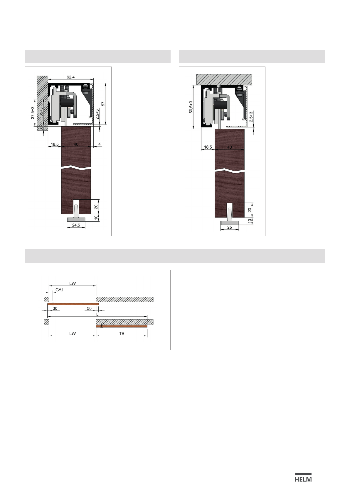
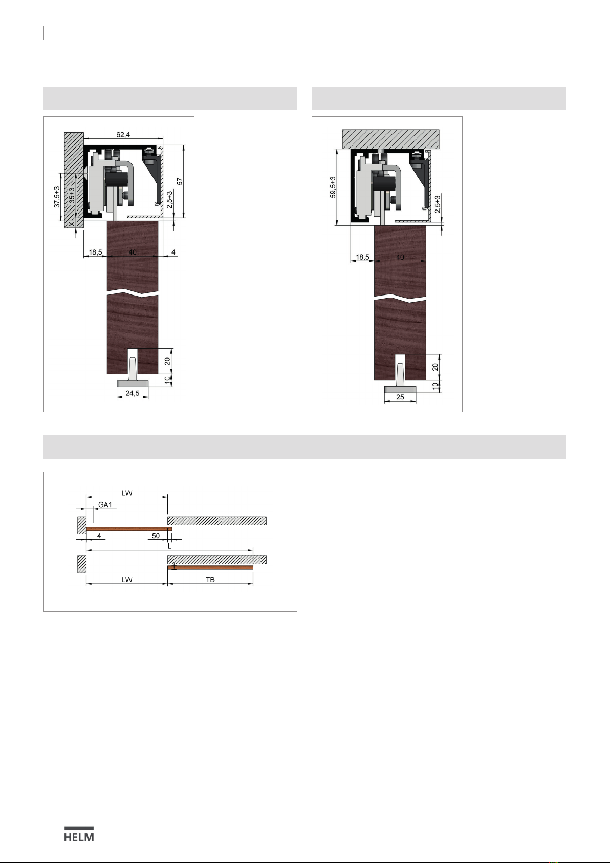
Türbreite Schiebetür (TB)
Door width sliding door (TB)
TB = LW + 50,00 - 4,00
Bsp.: / Example: TB = 950,00 + 50,00 - 4,00 = 996,00
Laufschienenlänge (L)
Track length (L)
L = TB + LW - GA1 - GA2 + 4,00
Bsp.: / Example: L = 996,00 + 950,00 - 80,00 - 60,00 + 4,00 = 1810,00
Durchgangsbreite (DB)
Walk-through distance (DB)
DB = LW - GA1 - GA2 + 4,00
Bsp.: / Example: DB = 950,00 - 80,00 - 60,00 + 4,00 = 814,00
Wand-/Deckenmontage bei nicht durchlaufender Wand, mit Stangengriff
Ceiling mount without continuous wall, with door handle
Wandmontage
Wall mount
Deckenmontage
Ceiling mount
Legende:
LH = lichte Höhe
LW = lichte Weite
BH = Bohrhöhe
TH = Türhöhe
TB = Türbreite Schiebetür
MG = Muschelgriff
L = Laufschienenlänge
GA1 = Griffabstand 1
GA2 = Griffabstand 2
DB = Durchgangsbreite
Legend:
LH = Clear height
LW = Clear width
BH = Drill height
TH = Door height
TB = Door width (sliding door)
MG = Flush pull
L = Track length
GA1 = Handle distance 1
GA2 = Handle distance 2
DB = Walk through distance
Bohrhöhe (BH)
Drilling height (BH):
BH = LH + X + 35
Türhöhe (TH)
Door heigth (TH):
TH = BH – 39 – 10
Türhöhe (TH)
Door height (TH):
TH = LH – 61 – 10
DS032023/11.2017
HELM GT-L 50
Montage / Installation