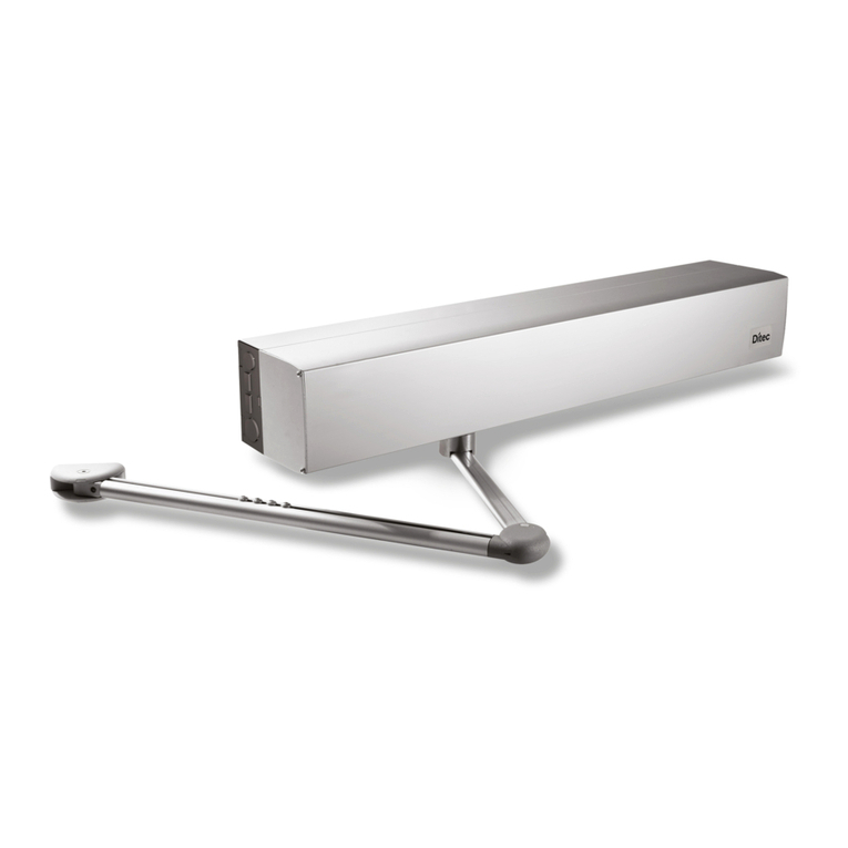
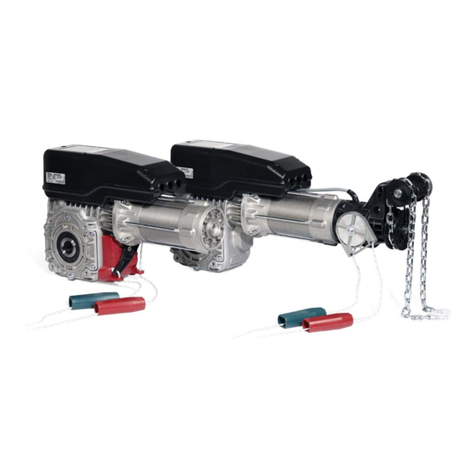
DITEC DOD User manual

Ditec DOD
Industrial sectional door
automations
(translation of the original instructions)
Technical manual
www.ditecautomations.com
IP2395EN • 2022-06-20
Last version of this manual

2
IP2395EN
Caption
This symbol indicates instructions or notes regarding safety, to which special atten-
tion must be paid.
This symbol indicates useful information for the correct functioning of the product.
Index
General safety precautions ...........................................................................................................................................3
Declaration of incorporation of partly completed machinery ......................................................................................5
UK Declaration of Conformity ..................................................................................................................................6
1. Technical data ...............................................................................................................................................7
1.1 Application .................................................................................................................................................................7
1.2 Machinery Directive ..................................................................................................................................................8
2. Dimensions .......................................................................................................................................................8
3. Installation type .............................................................................................................................................9
4. Ditec DOD14 axle installation .....................................................................................................................10
4.1 Motor assembling .................................................................................................................................................11
4.2 Installation ..............................................................................................................................................................11
5. Ditec DOD14 chain link-up installation ...................................................................................................12
5.1 Assembly of DODT drive shaft with Z24 pinion ...................................................................................................13
6. Cord release installation ................................................................................................................................14
7. Ditec DOD14 installed on sliding door ..................................................................................................15
8. Ditec DOD14 installed on sliding door ..................................................................................................15
9. Electrical connections ...................................................................................................................................16
9.1 Ditec DOD14 - DOITDD1P electrical connections ...................................................................................................16
9.1.1 Ditec DOITDD1P wiring diagram ....................................................................................................................................17
9.2 Product start-up ...................................................................................................................................................18
9.3 Limit switch adjustment ......................................................................................................................................19
9.4 Ditec DOD14PS electrical connections .............................................................................................................20
10. Routine maintenance plan ............................................................................................................................21

3
IP2395EN
General safety precautions
ATTENTION! Important safety instructions.
Follow these instructions carefully. Failing to follow the
instructions contained in this manual may result in serious
personal injury or damage to the equipment.
Keep these instructions for future reference.
This manual and the manuals for any accessories can be
downloaded at www.ditecautomations.com
This installation manual is intended for qualified personnel only •
Installation, electrical connections and adjustments must be car-
ried out by qualified personnel in accordance with Good Engineering
Practice and in compliance with the regulations in force • Read the
instructions carefully before starting to install the product. Incorrect
installation could cause dangerous situations • Check the integrity
of the product before starting installation
Packaging materials (plastic, polystyrene, etc.) should not be
discarded into the environment or left within the reach of
children, as they are potentially dangerous • Do not install the
product in an explosive environment or atmosphere. The presence
of flammable gases or fumes is a serious safety hazard • Ensure
that the operating temperature range indicated in the technical
data is compatible with the place of use • Before installing the
motorisation, check that the existing structure and the support
and guide components have the required strength and stability.
Check the stability and smoothness of the guided part and ensure
that there is no risk of derailment or falling. Make all structural
modifications necessary to create safety barriers and protect or
segregate all crushing, shearing, conveyance and danger zones
in general. The manufacturer of the motorisation system is not
liable for non-compliance with Good Engineering Practice in build-
ing the door or gate to be motorised or for any deformation that
may occur during use • The safety devices (photocells, sensitive
edges, emergency stops, etc.) should be installed in consideration
of the standards and directives in force, Good Engineering Practice,
the installation environment, the operating logic of the system and
the forces created by the motorised door or gate • The safety
4
IP2395EN
devices must protect any crushing, shearing, conveyance and
danger zones of the motorised door or gate. Apply the markings
provided for by the regulations in force to identify danger zones •
Each installation must have visible indication of the identification
data for the motorised door or gate • Before connecting the
power supply, make sure that the data on the plate correspond to
the electricity distribution network data. Provide an omnipolar
switch/disconnector on the power network with a contact opening
distance of 3 mm or more. Check that, upstream of the electrical
system, there is a suitable residual-current device and surge
protector, in compliance with Good Engineering Practice and the
regulations in force. • When required, connect the motorised door
or gates to an effective earthing system as indicated by the safety
regulations in force • Before handing over the system to the end
user, make sure that the automation is adequately adjusted to meet
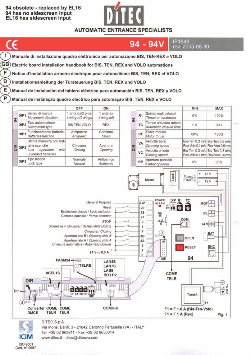
the operational and safety requirements and that all the command,
safety and manual release devices are working correctly.
During maintenance and repair work, disconnect the power
supply before opening the cover to access the electrical parts
• Only qualified personnel should remove the protective cover for
the automation system.
Electronic parts should be handled using grounded anti-
static conductive bracelets. The manufacturer of the mo-
torisation is not liable for safety or correct operation if incompat-
ible components are installed • Use only original spare parts for
any product repairs or replacements • The installer must provide
all information relating to the automatic, manual and emergency
operation of the motorised door or gate, and provide the user of
the system with the instructions for use and safety.

5
IP2395EN
Declaration of incorporation of partly completed machinery
(Directive 2006/42/EC, Annex II-B)
We,
ASSA ABLOY Entrance Systems AB
Lodjursgatan 10
SE-261 44 Landskrona
Sweden,
declare, under our sole responsibility, that the type of equipment with the name:
Ditec DOD14/14PS 230 V~ automation for sectional doors
Ditec DOITDD1P 230 V~ automation for sectional doors kit
complies with the following directives and their amendments:
2006/42/EC
Machinery Directive (MD), regarding the following essential health and safety requirements:
1.1.2, 1.1.3, 1.2.1, 1.2.2, 1.2.3, 1.2.4.2, 1.2.6, 1.3.9, 1.4.3, 1.7.2, 1.7.3, 1.7.4, 1.7.4.1, 1.7.4.2.
2014/30/EU Electromagnetic Compatibility Directive (EMCD)
2014/53/EU Radio Equipment Directive (RED)
2011/65/EU Restriction of Hazardous Substances (RoHS 2)
2015/863/EU Restriction of Hazardous Substances (RoHS Amendment 2)
Harmonised European standards which have been applied:
EN 61000-6-3:2007 + A1:2011 + AC:2012
EN 61000-6-2:2019
EN 60335-1:2012 + AC:2014 + A11:2014 + A13:2017 + A1:2019 + A14:2019 + A2:2019
EN 60335-2-103:2015
EN 60529:1991 + A1:2000 + A2:2013 + AC:2016
EN 62233:2008 + AC:2008
EN ISO 13849-1:2015
Other standards or technical specifications which have been applied:
IEC 60335-1:2010 + C1:2010 + C2:2011 + A2:2013 + C1:2014 + A2:2016 + C1:2016
IEC 60335-2-103:2006 + A1:2010
EN 12453:2017.
The manufacturing process guarantees that the equipment complies with the technical documentation.
Do not put equipment into service until the installed finished Automatic Entrance System has been
declared compliant with Directive 2006/42/EC on Machinery.
Responsible for the technical documentation:
Matteo Fino
BSP Ind channel & Gate Automation
Ditec S.p.A.
Largo U. Boccioni, 1
21040 Origgio (VA)
Italy
Signed on behalf of ASSA ABLOY Entrance Systems AB by:
Place Date Signature Position
Origgio 2022-06-20 Matteo Fino Head of Ind channel & Gate Automation
© ASSA ABLOY, All rights reserved

6
IP2395EN
UK Declaration of Conformity
We:
ASSA ABLOY Entrance Systems AB
Lodjursgatan 10
SE-261 44 Landskrona
Sweden
Declare under our sole responsibility that the types of equipment with names:
Ditec DOD14/14PS 230 V~ automation for sectional doors
Ditec DOITDD1P 230 V~ automation for sectional doors kit
Comply with the following directives and their amendments:
• Supply of Machinery (Safety) Regulations 2016
• Electromagnetic Compatibility Regulations 2016
• Radio Equipment Regulations 2017
• The Restriction of the Use of Certain Hazardous Substances in Electrical and Electronic
Equipment Regulations 2012 (RoHS)
Harmonized European standards that have been applied:
EN 61000-6-3:2007 + A1:2011 + AC:2012
EN 61000-6-2:2019
EN 60335-1:2012 + AC:2014 + A11:2014 + A13:2017 + A1:2019 + A14:2019 + A2:2019
EN 60529:1991 + A1:2000 + A2:2013 + AC:2016
EN 62233:2008 + AC:2008
EN ISO 13849-1:2015
Other standards or technical specifications that have been applied:
IEC 60335-1:2010 + C1:2010 + C2:2011 + A2:2013 + C1:2014 + A2:2016 + C1:2016
EN 12453:2017
The manufacturing process ensures the compliance of the equipment with the technical file.
Responsible for technical file:
Matteo Fino
BSP Ind channel & Gate Automation
Ditec S.p.A.
Largo U. Boccioni, 1
21040 Origgio (VA)
Italy
Signed for and on behalf of ASSA ABLOY Entrance Systems AB by:
Place Date Signature Position
Origgio 2022-06-20 Matteo Fino Head of Ind channel & Gate Automation
© ASSA ABLOY, All rights reserved

7
IP2395EN
1. Technical data
1.1 Application
Service class: 4 (minimum 100 cycles a day for 10 years or 200 cycles a day for 5 years)
Use: INTENSIVE (For pedestrian accesses with intensive use).
- The operating performance specifications refer to the recommended weight (about 2/3 of maxi-
mum allowed weight). Use with maximum allowed weight could reduce the above performance
specifications in tecnhical data.
-The service class, operating times and number of consecutive cycles are merely approximate.
These have been statistically determined in average conditions of use and are not certain for
each single case.
- Each automatic entrance features variable factors such as: friction, balancing and environ-
mental conditions that can substantially change both the duration and operating quality of
the automatic entrance or part of its components (including automatic system). It is up to the
installer to adopt adequate safety coefficients for each single installation.
The given operating and performance features can only be guaranteed with the use of
DITEC accessories and safety devices.
ATTENTION: DOD14 geared motors may be used for operating sectional doors only if
correctly balanced.
The sectional doors can only be manually moved by means of a handle (installing the
DODSBV release device) or a chain (installing the DODSBC release device).
Ditec DOD14 Ditec DOITDD1P Ditec
DOD14PS
Power supply 230 V~ 50 / 60 Hz
Absorption 3 A
Motor power 350 W
Torque 60 Nm
Holding torque 300 Nm
Revolution
transmission shaft 22 rpm
RPM controlled by limit switch
27.5
Capacitor 22 μf
Service class 4 - INTENSIVE
Continuous operating time (S2)
30 min
Intermittence (S3) 50%
Temperature (with NIO enable)
-20°C +55°C -35°C +55°C
-20°C +55°C
Degree of protection IP40
Weight 15 kg
Control panel LCA85 LCA85B -

8
IP2395EN
2. Dimensions
225
90
135
120
40
40
60
100
100
5
65
65
264
135
30 320
40
Ø25.4 (1")
6.35 (1/4")
6.35
(1/4")
9.5
(3/8")
NOTE: Unless otherwise specified, all measurements are in mm.
1.2 Machinery Directive
According to the Machinery Directive (2006/42/EC), the installer who motorises a door or gate has
the same obligations as the manufacturer of a machine, and as such must:
- prepare the technical documentation, which must contain the documents indicated in Annex V
of the Machinery Directive;
(the technical documentation must be kept and made available to the competent national
authority for at least ten years, starting from the date of construction of the motorised door);
- draw up the EC statement of conformity according to Annex II-A of the Machinery Directive and
hand it over to the customer;
- affix the CE marking to the motorised door in accordance with point 1.7.3 of Annex I of the
Machinery Directive.

9
IP2395EN
4
5
3
1
2
3. Installation type
Connect the power supply to an omnipolar approved switch with an opening distance of the
contacts of at least 3 mm (not included). The connection to the mains must be done on an
independent channel separate from the connections to the command and safety devices.
Ref. Code Description Cable
1 DOD14 Actuator (motor) 4 x 1.5 mm²
Extra low voltage limit switch unit 3 x 0.5 mm²
2 LCA85/LCA85B Control panel 3G x 1.5 mm²
3
FLM
FL24
Flashing light 230 V
Flashing light 24 V 2 x 1mm²
Antenna (integrated in the flashing light) RG-58 coax
cable (50 Ω)
4
AXK4
AXK5M
AXR5I
AXK5NM
AXK5NI
AXR7
Digital combination wireless keypad
Key metal burglar-proof semi-recessed selector switch
Key metal burglar-proof wall-mounted selector switch
Key metal burglar-proof semi-recessed selector switch
Transponder
/
4 x 0.5 mm²
5
SOFAP20
SOF2M20-SOF3M20
SOFA15-SOFA20-SOFA25
GOPAV
Safety edge
Safety edge
Safety edge
Safety signal’s radio transmission system
/

10
IP2395EN
4. Ditec DOD14 axle installation
WARNING: For correct operation we advise to move the door at a speed lower than 0.2 m/s.
DOD14
LCA85
LCA85B
FLM
FL24
AXK4
AXK5M
AXK5I
AXK5NM
AXK5NI
AXR7
SOFAP20
SOF2M20-SOF3M20
SOFA15-SOFA20-SOFA25
ØN
DOD14
Type Pinion Crown Reduction
ratio
Torque
[Nm]
Rotating
speed
[RPM]
Door cable
pulley
[Ø mm]
Door
speed
[m/s]
Max Run
[m]
Max force
[N]
DOD 14 - - 1:1 60 22
102
124
158
226
Ø
0,12
0,14
0,18
0,26
=Ø:868
8,7
10,6
13,6
19,4
=Ø:11,66
1176
968
759
531
=120000:Ø

11
IP2395EN
4.1 Motor assembling
Mount the DOD14 motor onto the wall bracket and release idle bracket as shown in figure.
4.2 Installation
- Fit the DOD14 motor onto the drive shaft.
- After having determined the position of the wall bracket, drill the holes and secure the bracket
in place with dowels (not supplied).
- Insert the appropriate cotter according to shaft cavity length.
- Secure the metal clamp so as to prevent the risk of the cotter coming out of the shaft.
ATTENTION: firmly tighten down all fastening screws.
min 130
1
2
3
6.35 (1/4")
6.35
(1/4")
9.5
(3/8")

12
IP2395EN
5. Ditec DOD14 chain link-up installation
NOTE: DODT - Drive shaft with Z24 pinion and key
3Gx1.5 mm²
3x0.5 mm² (limit switch)
4Gx1.5 mm² (motor)
DOD14
CAT1+
CATG
DODT
LCA85
LCA85B
ATTENZIONE: corona non di
nostra fornitura
Type Pinion Crown Reduction
ratio
Torque
[Nm]
Rotating
speed
[RPM]
Door cable
pulley
[Ø mm]
Door
speed
[m/s]
Max Run
[m]
Max force
[N]
DOD 14
DODT
1/2”x5/16”
Z= 24
1/2”x5/16”
Z= 30 1:1,25 75 17,6
102
124
158
226
Ø
0,09
0,11
0,15
0,21
= Ø:1085
7,0
8,5
10,8
15,5
= Ø:14.57
1470
1210
949
664
=150000:Ø
DODT
1/2”x5/16”
Z= 24
1/2”x5/16”
Z= 39 1:1.625 97.5 13.5
102
124
158
226
Ø
0.07
0.09
0.11
0.16
= Ø:1410.5
5.4
6.5
8.3
11.9
= Ø:18.95
1912
1573
1234
863
=195000:Ø
DODT
1/2”x5/16”
Z= 24
1/2”x5/16”
Z= 45 1:1.875 112.5 11.7
102
124
158
226
Ø
0.06
0.08
0.10
0.14
= Ø:1627.5
4.7
5.7
7.2
10.3
= Ø:21.86
2206
1815
1424
996
=225000:Ø
ATTENTION: crown not sup-
plied by us

13
IP2395EN
Fasten the wall fixing brackets and the release idle bracket onto the Ditec DOD14 motor and put the
shaft with the pinion into the position required for traction (on one of the two sides of the motor).
5.1 Assembly of DODT drive shaft with Z24 pinion

14
IP2395EN
6. Cord release installation
- Fasten the brackets to the gearmotor, then pass the release cord.
-Connect the ring and the handle to the release cord.
-Fasten the cord connection bracket at a height of at least 2.5 m from the ground, to avoid any
improper use by unauthorised persons. Attach the WARNING label to the motor.
The cord release on the sectional doors should only be used by skilled per-
sonnel, for adjusting the door balancing springs during the installation and
maintenance phases. DO NOT USE TO MOVE THE SECTIONAL DOORS MANUALLY.
VIAMONS.BANFI,3
21042CARONNOP.LLA(VA)
ITALY
TEL.02/963911FAX.02/9650314
DITEC
S.p.A.
DOORTYPE
YEAROFMANUFACTURE
VOLTAGESUPPLY
SERIALNUMBER
MadeinItaly
00000
00000000000
0000
000V
OPENING
min 2500 mm
UNLOCK
HOLD TO
UNLOCK
WARNING
EMERGENCY STOP
OPEN
TRAINED
PERSONNEL
ONLY
STOP

15
IP2395EN
7. Ditec DOD14 installed on sliding door
8. Ditec DOD14 installed on sliding door
OPENING
3Gx1.5 mm² [DOD14]
3x0.5 mm² (limitswitch)
4Gx1.5 mm² (motor)
LCA85
LCA85B
unlock
device
DOD14
DODT DODRIN1
3x0.5 mm² (limitswitch)
4Gx1.5 mm² (motor)
OPENING
3Gx1.5 mm² [DOD14]
DOD14
unlock
device
DODT DODRIN1
LCA85
LCA85B
Type Pinion Crown Reduction
ratio
Torque
[Nm]
Rotating
speed
[RPM]
Door speed
[m/s]
Max Run
[m]
Max Force
[N]
DOD14 DODT
(Z24)
DODRIN1
(Z24) 1:1 60 22 0,11 8,35 1200
Type Pinion Crown
Reduc-
tion
ratio
Torque
[Nm]
Rotating
speed
[RPM]
Door speed
[m/s]
Max Run
[m]
Max Force
[N]
DOD14 DODT
(Z24)
DODRIN1
(Z24) 1:1 60 22 0,11 8,35 1200
NOTE: for proper operation the door shall be equipped with a derailment device and the
chain fastening bracket on the wing must be rotating.

16
IP2395EN
9. Electrical connections
Before connecting the power supply, make sure the plate data correspond to those of the mains
power supply.
An omnipolar disconnection switch with a contact opening distance of at least 3 mm must be
fitted on the mains supply.
Check there is an adequate residual current circuit breaker and overcurrent cut-out upstream
of the electrical system.
Connect the motor wires to the respective control panel terminals.
WARNING: connect the motor earth wire to the power supply earth.
Connect the limit switch wires to the respective control panel terminals.
Secure the cable using a special cable clamp.
Make sure there are no sharp edges that may damage the power supply cable.
Connection to the mains power supply (in the section outside the automation) is made on an
independent channel, separated from the connections to the control and safety devices.
LCA85
LCA85B
~
LP 30 5 20
0 11A12A
LN UWV 016841
DOD14
-
~
~
+
FLM
RossoVerde
Cablaggio finecorsa
3x0.5 mm²
Cablaggio motore
4G x 1.5 mm²
freno
Finecorsa apertura
Finecorsa chiusura
com
STOP
V
W
U
12
11
0
M
1~
B
A
C
Contatto supplementare
9.1 Ditec DOD14 - DOITDD1P electrical connections
230 V~ - 50 / 60 Hz
Power supply
respect
polarity L-N
green red
Additional contact
Opening limit switch
Closing limit switch
Limit switch wiring
Motor wiring
Brake

17
IP2395EN
9.1.1 Ditec DOITDD1P wiring diagram
4G x 1,5 mm² (motor)
L= 5,3 m
5,3 m (3G x 1,5 mm²)
3 x 0,5 mm² (limit switch)
L= 5,3 m
LCA85B
230 V~ - 50 / 60 Hz
Power supply

18
IP2395EN
1. Turn on the power
2. Activate the configuration wizard menu.
Select the parameter value of 01 for operating
without slow-down, or 04 to activate deceleration during opening and closing. Deactivate auto-
matic closing by setting parameter
to
. Select the specific installation. Make sure the
opening direction parameter is correct (parameter )
.
3. Make a jumper for the safety contacts 1-6, 1-8 and 1-9. If not deactivated via the menu param-
eters → , → and → .
4. The limit switches must be set so that they intervene near the mechanical opening and closing
stop. To set the limit switches, see paragraph 7.3.
5. Perform a complete opening (keys
ENTER
+
UP
) and closing (keys
ENTER
+
DOWN
) cycle and check
that the automation performs the corresponding operation and stops when each limit switch
is activated (self-learning).
6. Adjust parameters → and → to regulate the extra operating time after ac-
tivation of the limit switches during opening and closing in order to precisely define the desired
final position. Several attempts may be required.
7. Activate automatic closing if necessary (parameter → ) and adjust the desired delayed
automatic closing (parameter → ).
8. Connect the safety devices after removing the jumpers 1-6, 1-8 and 1-9, or reactivating the cor-
responding inputs using the menu parameters → , → and → .
Make sure the various safety devices are operating correctly.
ATTENTION: if the control panel is used to replace an identical control panel which is
faulty, the last automation configuration can be reset by inserting the old control panel
storage module into the new control panel and loading the last set configuration using
the menu sequence → .
ATTENTION
: before using the automation, make sure that the operating forces of the gate
wings comply with the EN 12453:2017 standard and subsequent revisions.
9.2 Product start-up

19
IP2395EN
With door open, adjust screw [A] so as to cause the associated cam to trigger the opening limit
switch.
With door closed, adjust screw [C] so as to cause the associated cam to trigger the closing limit
switch.
You can decide to adjust the nut [B] so that the relative cam triggers the supplementary contact.
WARNING: the supplementary contact can be used for different purposes (i.e. as a safe-
ty in order not to exceed maximum stroke in closing and opening, as an exclusion of the
sensitive edge after the closing limit switch has been triggered, or for possible acoustic
signals or traffic lights).
9.3 Limit switch adjustment
A
A
B
BC
C
A
C

20
IP2395EN
10 m (4G x 1,5 mm²)
1,5 m (3G x 1,5 mm²)
12 11
LN
W
V
W
U
A
C
M
1~
-
~
~
+
B
Black
Brown
Grey
or
Blue
Brake
com
Yellow/Green
12
11
12B
11B
Opening limit switch
Additional switch
Closing limit switch
With the provided push button the control panel isn’t necessary, the automation works as “hold
to run” function.
9.4 Ditec DOD14PS electrical connections
230 V~ - 50 / 60 Hz
Power supply
Table of contents
Other DITEC Door Opening System manuals

DITEC
DITEC Sprint Manual

DITEC
DITEC Flash C User guide

DITEC
DITEC 94 System manual

DITEC
DITEC DAB305 User manual

DITEC
DITEC ENTREMATIC HA9 User manual

DITEC
DITEC DAS900FM User manual

DITEC
DITEC Sprint User manual

DITEC
DITEC DOD Series Instruction Manual

DITEC
DITEC DAS200T User manual

DITEC
DITEC PASP User manual