- 5-
2. RANDOM VOLTAGE GENERATOR
The random voltage generator generates random, staircase-like random pulses whose
voltage and time can be controlled in the following ways:
Time:
The internal clock, as determined by the mean rate regulator, may be free-running or only
subject to manual control so that the next random voltage is triggered by the manual
button (newer machines dont have this button anymore!) or an external pulse. In this
state, the module is a voltage-time converter. The frequency of the arbitrary pulses is
determined by the controller variation.
Voltage:
Two output voltages [V1, V2] are available and separately adjustable. Both are subject to
the same timing, i. H. the stepped control voltages are available at the same time at both
outputs [9, 10] on the patch panel.
In variation control position 0 no voltage variation is generated. Turning the variation knob
clockwise increases the randomness of the pulses.
The mean rate can be influenced via the patch panel [Q]. Positive and negative voltages
have an effect here.
In addition, a trigger pulse is sent when a random selection is made. The LED glows
more strongly depending on the trigger pulse.
The trigger pulse can be switched to the Envelope Generator (toggle switch Fig. 1.) or is
available at the output rvg trig out. These trigger spikes (>11V) are very short and not to
compare with standard gate signals. You can use it as a clock signal with a other machi-
nes f.e. drum machines / samplers (Korg Volca Sample.
NOTE: The trigger is a strong short signal (max. 11V) thus be careful using it with other
equipment! If you are in doubt don‘t use it!
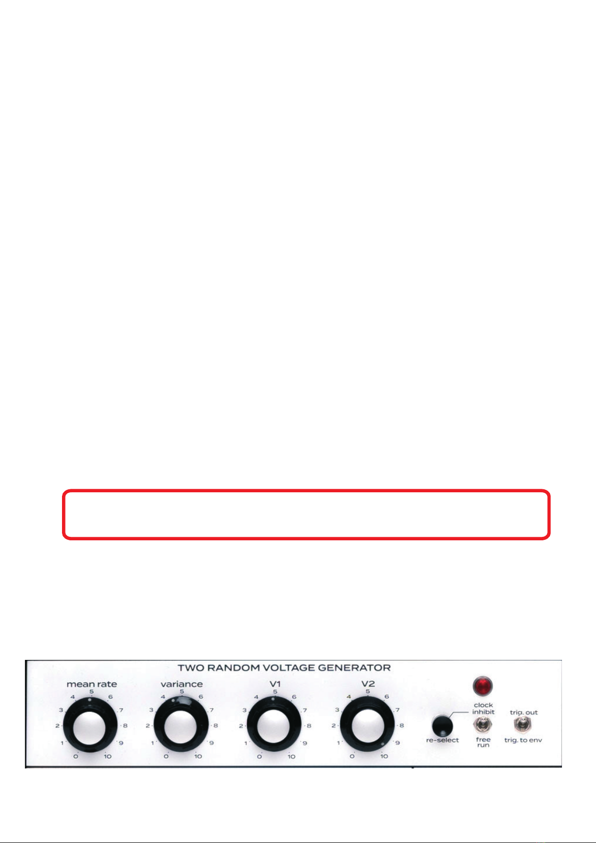
Controls:
mean rate speed of the time oscillator 0.2Hz (5s) to 20Hz
variation number of random pulses
V1 & 2: strength or modulation depth of the control voltage
Re-select switch f. manual triggering of the next random control voltage
clock inhibit external impulse release or manual
clock free run time oscillator freewheeling, controllable via the patch panel line [Q].