05 06
●
●
●
●
●
●
●
●
●
●
●
●
●
●
●
●
●
●
●
●
●
●
●
●
●
●
●
●
●
●
●
●
●
●
●
●
●
●
●
●
●
●
●
●
●
●
●Mount the saw on a piece 18 mm thick
MDF or Plywood board (800 x 500 min
●It may be necessary to countersink any
●Use ‘G’ clamps or similar to clamp the
●Never place your hands within the ‘no
●The work-piece must be firmly secured to
●Use the Hold Down clamp to secure the
●Do not attempt ‘awkward’ operations
●Before attempting a cut, make a ‘dry run’
●Keep your hands in position until the
●DO NOT OVER-REACH.
●Keep good footing and balance. Stand to
●
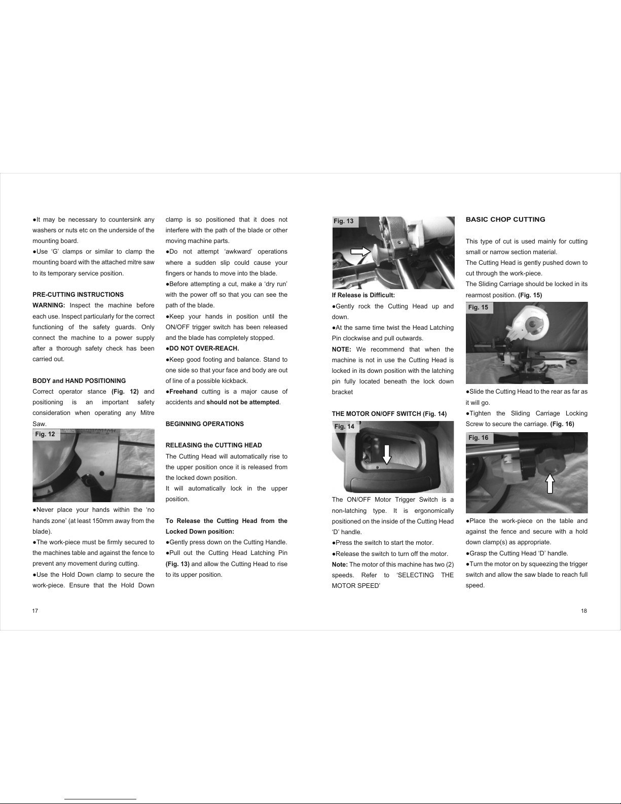
●Gently press down on the Cutting Handle.
●Pull out the Cutting Head Latching Pin
●Gently rock the Cutting Head up and
●At the same time twist the Head Latching
●Press the switch to start the motor.
●Release the switch to turn off the motor.
speeds. Refer to ‘SELECTING THE
●Slide the Cutting Head to the rear as far as
●Tighten the Sliding Carriage Locking
●Place the work-piece on the table and
●Grasp the Cutting Head ‘D’ handle.
●Turn the motor on by squeezing the trigger
●Operate the lower guard locking/release
●Lower the Cutting Handle downwards and
●Allow the speed of the blade to do the
●When the cut has been completed,
●Allow the Cutting Head to rise to its upper
●Only remove the work-piece when the
●Position the work-piece on the table and
●Loosen the Sliding Carriage Locking
●Grasp the Cutting Handle and pull the
●Operate the ON/OFF motor trigger switch
●Operate the lower blade guard locking
●Push the Cutting Handle all the way down
●Gently push the Cutting Handle rearwards
●Always push the Cutting Head to the full
●Loosen the Mitre Locking Handle
●Pull up the Positive Stop Locking Lever.
●Turn the rotary table to the desired angle.
●Tighten the Mitre Locking Handle when
●Loosen the socket headed screw.
●Slide the upper section of the Fence
●Conduct a ‘dry run’ with the power off to
●Loosen the Bevel Locking Handle.
●Tilt the Cutting Head to the desired angle.
●Ensure the handle is tightened securely
●Select the required Mitre angle as
CUTTING.
●Select the required Bevel angle as
CUTTING.
●Ensure the tightness of all locking screws
●Turn machine “OFF” by releasing the
●Allow the blade to come to a complete
●Unplug the machine from the mains
●Carefully remove any jammed material
●Check the condition and operation of the
●Check for any other damage to any part of
●Have any damaged parts replaced by a
you are tired or under the influence of
drugs, alcohol or medication.
A moment
of inattention while operating power tools
may result in serious personal injury.
b) Use personal protective equipment.
Always wear eye protection.
Protective
equipment such as dust masks, non-skid
safety shoes, hard hat or hearing protection
used for appropriate conditions will reduce
personal injuries.
c) Prevent unintentional starting. Ensure
the switch is in the off-position before
connecting to power source and or
battery pack, picking up or carrying the
tool.
Carrying power tools with your finger
on the switch or energising the power tools
that have the switch on invites accidents.
d)Remove any adjusting key or wrench
before turning the power tool on.
A
wrench or key left attached to a rotating part
of a power tool may result in personal
injury .
e) Do not overreach. Keep proper footing
and balance at all times.
This enables
better control of the power tool in
unexpected situations.
f) Dress properly. Do not wear loose
clothing or jewellery. Keep your hair,
clothing and gloves away from moving
parts.
Loose clothes, jewellery or long hair
can be caught in moving parts.
g) If devices are provided for the
connection of dust extraction and
collection facilities, ensure that these are
connected and properly used.
Use of dust collection can reduce
dust-related hazards.
4) General Power Tool Safety Warnings
[Power tool use and care].
a)Do not force the power tool. Use the
correct power tool for your application.
The correct power tool will do the job better
and safer at a rate for which it was
designed.
b) Do not use the power tool if the switch
does not turn it on or off.
Any power tool
that cannot be controlled with the switch is
dangerous and must be repaired.
c) Disconnect the power tool from the
power source and/or battery pack from
the power tool before making any
adjustments, changing accessories, or
storing power tools.
S
uch preventative
safety measuresreduce the risk of starting
the power tool accidentally.
d) Store idle power tools out of the reach
of children and do not allow persons
unfamiliar with the power tool or these
Instructions to operate the power tool.
Power tools are dangerous in the hands of
untrained users.
e)Maintain power tools. Check for
misalignment or binding of moving parts,
breakage of moving parts and any other
condition that may affect the power tools
operation. If damaged, have the power
tool repaired before use.
Many accidents
are caused by poorly maintained power
tools
f) Keep cutting tools sharp and clean.
Properly maintained cutting tools with
sharp cutting edges are less likely to bind
and are easier to control.
g) Use the power tool, accessories and
tool bits etc. In accordance with these
instructions, taking into account the
working conditions and the work to be
performed.
Use of the power tool for
operations different from those intended
could result in a hazardous situation.
5) General Power Tool Safety Warnings
[Service]
a) Have your power tool serviced by a
qualified repair person using only
identical replacement parts.
This will
ensure that the safety of the power tool is
maintained.
PACKAGING
Please safely retain the original packaging
during the guarantee period of your
machine. In the event of you having to
return your Pingtek machine, it should be
repackaged in its original packaging, so that
damage to the machine during transit can
be avoided. Pingtek is not liable for damage
that occurs during transit. This will be the
responsibility of the packers and/or
couriers.
The original packaging is recyclable.
Please dispose of the original packaging in
an environmentally responsible manner.
Additional safety rules for
your Mitre Saw
(Based on the requirements of
EN61029-2-9:2009)
WARNING: Circular Saw Blades are
extremely dangerous, and can cause
serious injury.
Observing the following
safety rules will help you minimise the risks
involved.
● Keep hands and fingers at least 150mm
away from the blade at all times.
● Only use blades that are specified by
the manufacturer, and as detailed in this
Instruction Manual.
● Blades must comply with the
requirements of EN 847-1
● Do not use blades that are damaged,
cracked, dull or deformed in any way.
● Do not use Blades that are
manufactured from high speed steel
(HSS).
● Never attempt to retrieve cut material
until the cutting head is in its upper
position, the lower blade guard is fully
closed, and the blade has stopped
revolving.
● Always wear Personal Protective
Equipment (PPE) suitable for the task at
hand. This could include:
●Ear Defenders to reduce the risk of
induced hearing loss.
●Safety glasses to defend the operators
●Dust masks to provide protection from
●Safety gloves should be worn when
●Carry saw blades in a holder whenever
●Only use this saw to cut materials which
●Check the operation of all the machines
●Check that the fitted saw blade is
●If fitted with a laser cutting guide this
●Only replace the saw blade by following
●Keep the work area as clean and tidy as
●Whenever possible secure the
●Ensure that the Mitre Saw is mounted in
●The Mitre Saw can be mounted directly
●Long work-pieces should be
●All operators using this machine must
●Never leave the saw unattended and
●Hold the saw close to your body during
●Lift by using the handhold areas
●Never use the power cord to lift or move
●Do not use the blade guard as a lifting
●Remember to remove the mains plug
●Before moving the saw check:
●
●
●
●
●When repositioning the machine at a
●Loosen the knurled locking nut.
●Adjust the depth stop screw to limit the
●Once set to the desired depth, tighten the
●When cutting is complete, return the depth
●Ensure the Cutting Head is in the upper
●Operate the lower guard locking/release
●Rotate the lower guard up and into the
●Press the arbor lock button to lock the
●Using the supplied Hex Key release the
.●Install the outer blade flange, washer and
●Ensure the Hex Key is removed and the
●Loosen the Repeat Stop thumb screws
●Position the Repeat Stop approximately half way
●Attach the Workpiece Support Bar to the
●Remove the six (6) cross-head screws that
●Lift the insert from the table.
●Remove any debris that may have accumulated
●Fit the replacement insert, and replace the six
●Check that all of the fixing screws are tightened
exist. Check with your relevant Government
UK TECHNICAL/SERVICE
Tel: 01484 443541