Pintech PT-710 User manual

▉PT-710
(100KHz,100A
100mV/A,10mV/A)
INSTRUCTION MANUAL
General Safety Instructions:
Read the following safety instructions to avoid injury and prevent damage to this product or any
products connected to it. Use this product only as specified.
Only qualified personnel should perform service procedures.
To Avoid Fire or Personal Injury
Connect and Disconnect Properly.
Connect the probe output to the measurement instrument before connecting the probe to the circuit
under test. Disconnect the probe input and the probe ground from the circuit under test before
disconnecting the probe from the measurement Instrument.
Observe All Terminal Ratings.
To avoid fire or shock hazard, observe all rating and markings on the product. Consult the
PT-710 AC/DC current probe

instruction manual for further ratings information before making connections to the product.
Replace Batteries Properly.
Replace batteries only with the proper type and rating specified.
Do Not Operate Without Covers.
Do not operate this product without the covers or panels.
Avoid Exposed Circuitry.
Do not touch exposed connections and components when power is present.
Do Not Operate With Suspected Failures.
If you suspect there is damage to this product, have it inspected by qualified service personnel.
Do Not Operate in Wet/Damp Conditions.
Do Not Operate in an Explosive Atmosphere.
Keep Product Surfaces Clean and Dry.
Safety Terms and Symbols:
Terms in This Manual.
These terms may appear in this manual.
WARNING.
Warning statements identify conditions or practices that could result in injury or loss of life.
CAUTION.
Caution statements identify conditions or practices that could result in damage to this product or
other property.
Terms on the Product.
These terms may appear on the product.
DANGER
Indicates an injury hazard immediately accessible as you read the marking.
WARNING indicates an injury hazard not immediately accessible as you read the marking.
CAUTION
Indicates a hazard to property including the product.
Symbols on the Product.
These symbols may appear on the product: Attention refer to operation Instructions.
This instrument has double insulation.
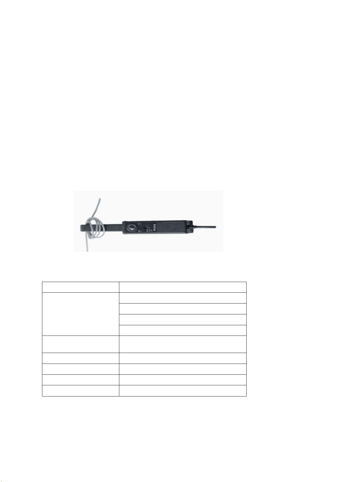
Getting Started:
The current probe enables a general purpose oscilloscope to display AC and DC current signals up
to 100 amps Peak (70A RMS). The current probe can also make AC and DC measurements with a
multimeter by using the recommended accessory MT-246N (BNC-to-banana) plug adapter.

PIC 1
Shows the controls and indicators on the current probe.
Output Into
Press Button
Battery Cover
Range Selection
(Power On/Off)
DC Zero Offset
Test Position
Max. 11¢Wire
Control/Indicator
Description
Current flow symbol. The arrow shows the probe’s polarity
convention for measuring current flowing from positive to
negative.
Zero adjustment. Rotate to adjust the probe output to zero
when there is no current present. It may also be used to offset a
DC signal component. Zeroing is not needed for AC
measurements unless your instrument cannot isolate a DC
component (if present).
OFF/Range switch. Slide the switch from OFF to either the
100 mV/A or 10mV/A range. When either range is selected,
the probe is turned on, and the green battery indicator lights. If
the indicator does not light, see Battery Notes and Battery
Installation.
Battery indicator. The green battery indicator lights when the
probe is turned on. For more information, see Battery Notes
and Battery Installation .
Overload indicator. The red overload indicator lights if the
measured signal is greater than the selected range capacity.
Switch the probe to 5 mV/A if possible, or remove the probe
from the circuit.

These characteristics apply to an adjusted PT-710 AC/DC Current Probe installed on an
oscilloscope of any brand. The oscilloscope must be warmed up for at least 20 minutes and be in
an environment with the
temperature at 10℃~30℃and the humidity at 0~80.
Environmental Characteristics
Basic Operation:
Before using the probe, the batteries must be installed.
WARNING!
Do not clamp the probe onto circuits with voltages greater than 600 VAC. Personal injury or
damage to the probe may result. Always connect the PT-710 current probe output to the
instrument before clamping onto the circuit under test.
1. First connect the current probe BNC connector to BP-250 (double BNC connection cable) then
connect to oscilloscope input. Start by setting the oscilloscope voltage input channel to DC volts,
and the voltage sensitivity scale to 5m V/div.
2. Move the OFF/ Range switch to the 100mV/A or 10mV/A position to turn on the probe. (※The
PT-710 current probe has a green LED power/battery indicator. If the LED does not light, replace
the battery or use specified power adaptor.)
3. Use the ZERO adjustment to zero or offset the probe output detection of residual magnetic DC
charges.
4. Connect the probe to the circuit by opening the jaws and clamping around the conductor.
NOTE. Clamping around both the “hot” and neutral wires may give you a zero
reading. (Remember to unclamp the probe from the conductor before disconnecting
it from your meter or instrument).
Size
231 mm x67 mm x 36 mm
Maximum Conductor
Size
11 mm
Cable Length
200 cm
Weight
310 g (without battery)
Temperature
Working
Storage
0°C to +50°C
(+32°F to +122°F)
-20°C to +80°C
(-4°F to +176°F)
Humidity
0°C to 40°C, 95% humidity
40°C to 50°C, 45% humidity
Pollution Degree
2

Current Range
100mV/A ; 10mV/A
DC Accuracy, typical
±2% ±5mV
(0.2A to 10 A peak at 100mV/A range)
±2% ± 5mV
(10A to 100 A peak at 10mV/A range)
Maximum Current
100A
Frequency Range
DC to 100KHz (-3 dB)
Rise time,typical
3.5uS
Noise
2mV
Battery
9V battery
5. Adjust the probe channel and oscilloscope’s time base as necessary to get a clear and stable
view of the signal. Set the oscilloscope input to DC volts to see both the AC and DC currents; set
the channel to AC to see the AC current only.
6. The current drawn by different devices look much more different than that of others. While the
RMS current can only be used in low frequency current, the momentary peaks may be quite high.
7. PT-710, a multifunctional current probe. When connecting to a digital meter, use the
recommended MT-246N (BNC-to-banana adapter). Connect the black lead to the meter COM
(black letters on the meter), and the red lead to the VΩ input (red letters on the meter).
8.To measure only AC current, set the meter to measure AC volts.
9.To measure DC current, set the meter to measure DC volts. Note the current convention arrow
on the probe to get the proper polarity reading.
10.To increase the measurement sensitivity of the PT-710 current probe, loop additional turns of
the wire under test through the jaws. See below pic.
The sensitivity of the PT-710 current probe is multiplied times the number of loops in the jaws.
For example: 10mV/A X5 turns=50mV/A
Electrical Characteristics

測定
Maximum working
current(A)
Maximum
Working
voltage (V)
Maximum
floating
voltage (V)
Rating
Range
10mV/
A
Range
100mV/A
Max. Working
voltage (V)
Max. floating
voltage (V)
DC
100
10
600
600
DC +peak AC
100
10
600
600
AC peak
100
10
600
600
AC
peak-peak
200
20
1200
-
RMS CAT
III
70
7
600
600
RMS
CAT II
70
7
600
600
RMS CAT I
70
7
600
600
Voltage and current ratings
8
Table of contents