Contents
23A4558F Repair, Parts
Contents
Warnings . . . . . . . . . . . . . . . . . . . . . . . . . . . . . . . . . 3
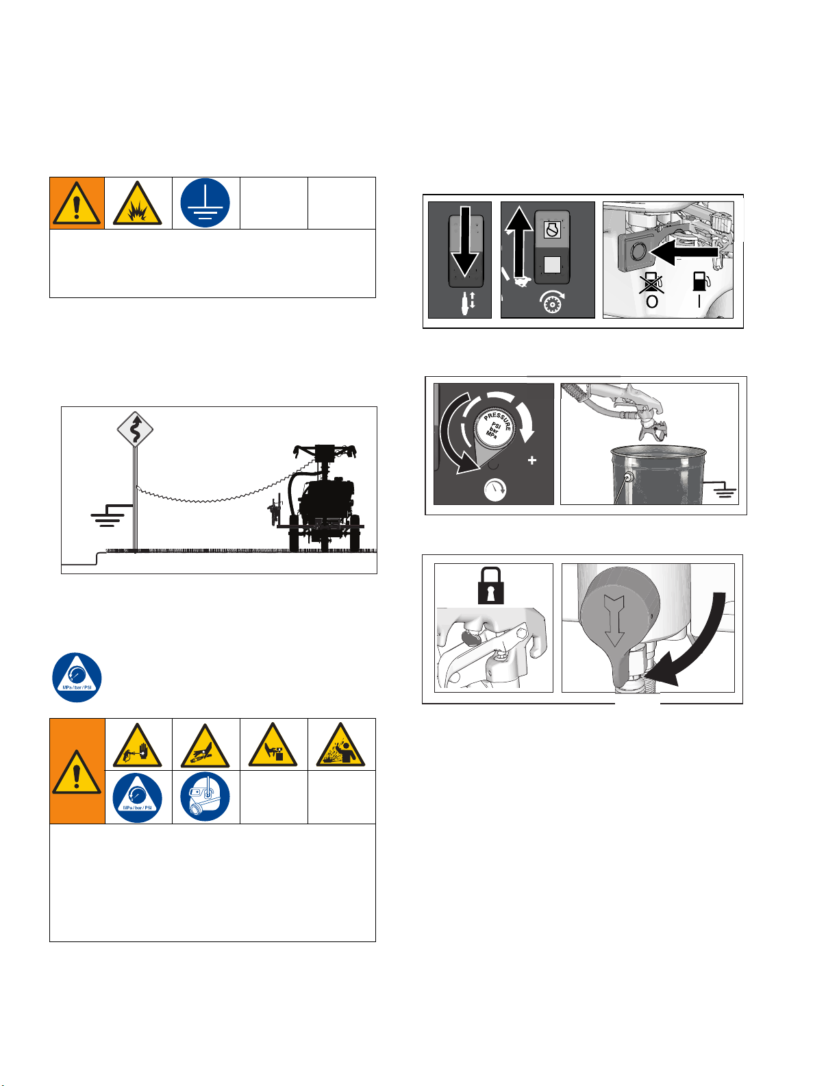
Grounding Procedure (For Flammable Materials
Only) . . . . . . . . . . . . . . . . . . . . . . . . . . . . . . . . . . 6
Pressure Relief Procedure . . . . . . . . . . . . . . . . . . . 6
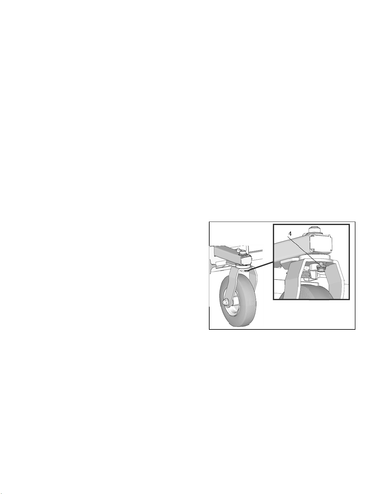
Maintenance . . . . . . . . . . . . . . . . . . . . . . . . . . . . . . . 7
Front Wheel Alignment: . . . . . . . . . . . . . . . . . . . 7
Troubleshooting . . . . . . . . . . . . . . . . . . . . . . . . . . . 8
Displacement Pump . . . . . . . . . . . . . . . . . . . . . . . 10
Removal . . . . . . . . . . . . . . . . . . . . . . . . . . . . . . 10
Repair . . . . . . . . . . . . . . . . . . . . . . . . . . . . . . . . 10
Installation . . . . . . . . . . . . . . . . . . . . . . . . . . . . . 11
Drive Housing and Connecting Rod . . . . . . . . . . 12
Removal . . . . . . . . . . . . . . . . . . . . . . . . . . . . . . 12
Installation . . . . . . . . . . . . . . . . . . . . . . . . . . . . . 12
Pinion Assembly/Clutch Armature/Clamp . . . . . 13
Pinion Assembly/Clutch Armature Removal . . . 13
Installation . . . . . . . . . . . . . . . . . . . . . . . . . . . . . 14
Clamp Removal . . . . . . . . . . . . . . . . . . . . . . . . 15
Clamp Installation . . . . . . . . . . . . . . . . . . . . . . . 15
Clutch Housing . . . . . . . . . . . . . . . . . . . . . . . . . . . 16
Removal . . . . . . . . . . . . . . . . . . . . . . . . . . . . . . 16
Installation . . . . . . . . . . . . . . . . . . . . . . . . . . . . . 16
Engine . . . . . . . . . . . . . . . . . . . . . . . . . . . . . . . . . . . 17
Removal . . . . . . . . . . . . . . . . . . . . . . . . . . . . . . 17
Installation . . . . . . . . . . . . . . . . . . . . . . . . . . . . . 17
Pressure Control Transducer . . . . . . . . . . . . . . . . 18
Removal . . . . . . . . . . . . . . . . . . . . . . . . . . . . . . 18
Installation . . . . . . . . . . . . . . . . . . . . . . . . . . . . . 18
Pressure Control (On/Off Switch) . . . . . . . . . . . . 19
Removal . . . . . . . . . . . . . . . . . . . . . . . . . . . . . . 19
Installation . . . . . . . . . . . . . . . . . . . . . . . . . . . . . 19
Pressure Adjust Potentiometer . . . . . . . . . . . . . . 20
Removal . . . . . . . . . . . . . . . . . . . . . . . . . . . . . . 20
Installation . . . . . . . . . . . . . . . . . . . . . . . . . . . . . 20
Control Board . . . . . . . . . . . . . . . . . . . . . . . . . . . . 20
Removal . . . . . . . . . . . . . . . . . . . . . . . . . . . . . . 20
Installation . . . . . . . . . . . . . . . . . . . . . . . . . . . . . 20
Battery . . . . . . . . . . . . . . . . . . . . . . . . . . . . . . . . . . 21
Removal . . . . . . . . . . . . . . . . . . . . . . . . . . . . . . 21
Installation . . . . . . . . . . . . . . . . . . . . . . . . . . . . . 22
Drive Motor . . . . . . . . . . . . . . . . . . . . . . . . . . . . . . . 22
Removal . . . . . . . . . . . . . . . . . . . . . . . . . . . . . . 22
Installation . . . . . . . . . . . . . . . . . . . . . . . . . . . . . 24
Drive Wheels . . . . . . . . . . . . . . . . . . . . . . . . . . . . . 26
Removal . . . . . . . . . . . . . . . . . . . . . . . . . . . . . . 26
Installation . . . . . . . . . . . . . . . . . . . . . . . . . . . . . 26
Drive Switch . . . . . . . . . . . . . . . . . . . . . . . . . . . . . . 27
Removal . . . . . . . . . . . . . . . . . . . . . . . . . . . . . . 27
Installation . . . . . . . . . . . . . . . . . . . . . . . . . . . . . 28
Drive/Axle Bearings . . . . . . . . . . . . . . . . . . . . . . . . 29
Removal . . . . . . . . . . . . . . . . . . . . . . . . . . . . . . 29
Installation . . . . . . . . . . . . . . . . . . . . . . . . . . . . . 30
Drive Chain . . . . . . . . . . . . . . . . . . . . . . . . . . . . . . . 32
Removal . . . . . . . . . . . . . . . . . . . . . . . . . . . . . . 32
Installation . . . . . . . . . . . . . . . . . . . . . . . . . . . . . 32
Motor Control Board . . . . . . . . . . . . . . . . . . . . . . . 33
Removal . . . . . . . . . . . . . . . . . . . . . . . . . . . . . . 33
Installation . . . . . . . . . . . . . . . . . . . . . . . . . . . . . 34
Speed Control . . . . . . . . . . . . . . . . . . . . . . . . . . . . 35
Removal . . . . . . . . . . . . . . . . . . . . . . . . . . . . . . 35
Installation . . . . . . . . . . . . . . . . . . . . . . . . . . . . . 36
Troubleshooting . . . . . . . . . . . . . . . . . . . . . . . . . . . 37
Drive System . . . . . . . . . . . . . . . . . . . . . . . . . . . 37
Fluid Pump Runs Constantly . . . . . . . . . . . . . . . 38
Control Board Malfunction . . . . . . . . . . . . . . . . . 39
Control Board Malfunction (Steps) . . . . . . . . . . 40
Digital Display Messages . . . . . . . . . . . . . . . . . 41
Parts Drawing . . . . . . . . . . . . . . . . . . . . . . . . . . . . . 42
25M230 . . . . . . . . . . . . . . . . . . . . . . . . . . . . . . . 42
Parts List - 25M230 . . . . . . . . . . . . . . . . . . . . . . . . 43
Parts Drawing . . . . . . . . . . . . . . . . . . . . . . . . . . . . . 44
Self-Propelled Drive - Series A . . . . . . . . . . . . . 44
Parts List - Self-Propelled Drive - Series A . . . . . 45
Parts Drawing . . . . . . . . . . . . . . . . . . . . . . . . . . . . . 46
Self-Propelled Drive - Series B . . . . . . . . . . . . . 46
Parts List - Self-Propelled Drive - Series B . . . . . 47
Parts Drawing . . . . . . . . . . . . . . . . . . . . . . . . . . . . . 48
Parts List - 25M230 . . . . . . . . . . . . . . . . . . . . . . . . 49
Parts Drawing and List - Pinion Housing . . . . . . 50
Gun Arm Parts . . . . . . . . . . . . . . . . . . . . . . . . . . . . 51
Pressure Control/Filter Assembly . . . . . . . . . . . . 52
Parts List - Pressure Control/Filter Assembly . . 53
Pressure Control Wiring Diagram . . . . . . . . . . . . 54
Drive Control Wiring Diagram . . . . . . . . . . . . . . . . 55
PIONEER LIMITED WARRANTY . . . . . . . . . . . . . . 56