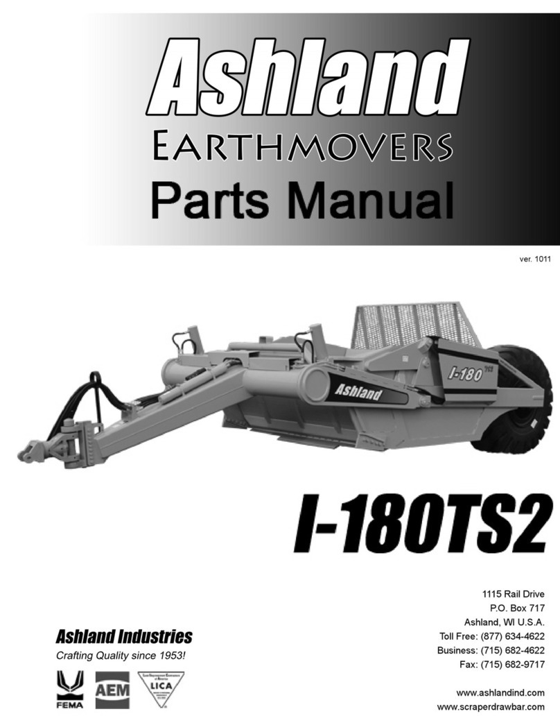
Ashland Earthmovers I-175XL2 User manual

Earthmovers
ver. 0811
1115 Rail Drive
P.O. Box 717
Ashland, WI U.S.A.
Toll Free: (877) 634-4622
Business: (715) 682-4622
Fax: (715) 682-9717
wwwww.ashlandind.com
www.scraperdrawbar.com

ASHLAND SCRAPERS
Serial Number
WELCOME TO OUR NEW CUSTOMERS!
Thank you for your purchase of an Ashland scraper and the confidence you have placed in us to
handle your earthmoving projects. Years of research, testing and successful application have
been spent to ensure quality and maximum performance for our customers. Please read and
understand this manual before attempting to attach or operate this scraper. This manual should
always remain with the machine. Be sure and fill out and send in the owners re
g
istration form at
the beginning of this manual, or you may fill out the form on-line by
g
oin
g
to ashlandind.com and
click on “Register your Machine” at the bottom of the page.
SCRAPER ID NUMBER
The serial number plate for the scraper is located on the right rear area of the scraper. The
letter and numbers stamped identify the serial number, model number and capacity of the
scraper. Please record this serial number for use in orderin
g
parts, warrantee issues and to trace
your equipment if it is ever stolen.
References to serial number breaks on parts are located in the manual with a reference sequence
of XXXXX-XXXXX. The beginning number records the serial number start of the use of that part.
The ending number is the final serial number use of the part within this machine.
PHONE : 715-682-4622 Fax: 715-682-9717
P.O. Box 717
1115 Rail Dr
A
shland , WI 54806
Page #1

ASHLAND SCRAPERS
How to Order Parts
HOW TO ORDER PARTS:
IMPORTANT
Parts must be ordered through your local authorized ASHLAND dealer.
Be sure to state MODEL and SERIAL NUMBER of your machine, PART NUMBER, DESCRIPTION
and QUANTITY needed.
Unless this is done, we cannot provide prompt service or assure shipment of the correct parts.
Ashland Industries weldable replacement parts are available to rebuild, modify or update your
scraper to current factory specifications.
PHONE : 715-682-4622 Fax: 715-682-9717
P.O. Box 717
1115 Rail Dr
A
shland , WI 54806
Page #2

ASHLAND SCRAPERS
Operators and Maintenance
This scraper is a durable piece of equipment and with proper care will yield many years of trouble free
operation. The scraper requires a power source with TWO 4 way (double acting) hydraulic control
valves.
The scraper should be greased at all points where
g
rease fittin
g
s are provided. Check the oil levels in
the tractor hydraulic system and add to maintain the proper level. Care should be used when adding oil
or when disconnecting any oil line to keep all dirt out of the oil as dirt is a major factor in the failure of
hydraulic components.
When the scraper is placed into operation, the operator will have to “feel out” the amount of depth of
cut to obtain maximum loading efficiency. This is usually accomplished by taking a lesser and more
uniform cut; however, some soil conditions such as loose sand may require a “pumping action” obtained
by taking successive deep cuts and lifting out of cut as the tractor begins to lose power or traction.
1. After 10 hours work, all bolts should be checked and tightened if necessary.
2. Every 10 hours all grease fittings should be lubricated.
3. After 50 hours work, all bolts should be rechecked and tightened if necessary. Check wheel
bearings and adjust if necessary.
4. After 300 hours work, clean and repack wheel bearings and replace, if necessary, cutting edges,
worn pins, etc.
PHONE : 715-682-4622 Fax: 715-682-9717
P.O. Box 717
1115 Rail Dr
A
shland , WI 54806
Page #3

ASHLAND SCRAPERS
XL Assembly
PHONE : 715-682-4622 Fax: 715-682-9717
P.O. Box 717
1115 Rail Dr
A
shland , WI 54806
Page #4

ASHLAND SCRAPERS
Safety Guidelines
GENERAL SAFETY GUIDELINES
Safety of the operator is one of the main concerns in designing and developing a new piece of
equipment. Designers and manufacturers build in as many safety features as possible. However, every
year many accidents occur which could have been avoided by a few seconds of thought and a more
careful approach to handling equipment. You, the operator, can avoid many accidents by observing the
following precautions in this section. To avoid personal injury, study the following precautions and insist
those working with you, or for you, follow them.
Replace any CAUTION, WARNING, DANGER or instruction safety decal that is not readable or is missing.
Location of such decals is indicated in this booklet.
Do not attempt to operate this equipment under the influence of drugs or alcohol.
Review the safety instructions in the operator’s manual with all users annually.
This equipment is dangerous to children and persons unfamiliar with its operation. The operator should
be a responsible adult familiar with farm or construction machinery and trained in this equipment’s
operations. Do not allow persons to operate or assemble this unit until they have read this
manual and the owner’s manual and have developed a thorough understanding of the safety
precautions and how the machine works.
To prevent injury or death, use a tractor equipped with a Roll Over Protective System (ROPS). Do not
paint over, remove or deface any safety signs or warning decals on your equipment. Observe all safety
signs and practice the instructions on them.
Never exceed the limits of a piece of machinery. If its ability to do a
j
ob, or to do so safely, is in question
- DON’T TRY IT.
PHONE : 715-682-4622 Fax: 715-682-9717
P.O. Box 717
1115 Rail Dr
A
shland , WI 54806
Page #5

ASHLAND SCRAPERS
Gooseneck Frame Assembly (175)
KEY PART DESCRIPTION
1A17507 Gooseneck Frame
1AFB-00080 Bolt 5/16” NC x 1/2” Lg.
2AFB-00079 Bolt, 5/8 NC X 1 1/2" Gr. 8
314505 Grease Zerk - Straight
4A123321-09 Main Frame Pin
5A123358 Bushing Pin Keeper
6A123230-20 Travel Lock
7AFB-00081 "Bolt, 7/8”NF x 5” Lg. Grade 5"
87597 "Nut, 7/8”NF"
98125 Lockwasher 7/8”
10 A14002 Cast Socket Half - Rear
11 A14003 Cast Socket Half - Front w/Zerk Hole
12 A2206 Grease Zerk - Long Shank
13 A123320-08 "Bushing, 3 ID X 3.5 OD X 3"
14 OPT-00001 Hitch Jack
15 A123321-89 Bushing Pin Keeper
15 A125006 Safety Link Pin
PHONE : 715-682-4622 Fax: 715-682-9717
P.O. Box 717
1115 Rail Dr
A
shland , WI 54806
Page #6

ASHLAND SCRAPERS
Apron Assembly (175)
KEY PART DESCRIPTION
1A17505 Apron Model 175
2A16027 Bushing: 1 1/2 ID X 2 OD X 2" L
3A123337 Pin: Apron Pivot 110TS-175XL2
47450 Nut: 3/8" NC
5AFB-00049 Bolt: 3/8" NC X 3"
614505 Grease Zerk-straight
PHONE : 715-682-4622 Fax: 715-682-9717
P.O. Box 717
1115 Rail Dr
A
shland , WI 54806
Page #7

PHONE : 715-682-4622 Fax: 715-682-9717
Bowl & Frame Assembly (155-175-1200)
KEY PART DESCRIPTION
1A17503 Bowl and Frame Model 175
2AFB-00094 Flanged Bolt: 3/8 NC X 1"
3A123309-62L Apron Cylinder Guard - Left Side
4A123309-62R Apron Cylinder Guard - Right Side
5A123332L Left Cutting Edge-8" X22 1/2" X 7/8" Hardened
6A123330 Center Cutting Edge, 1 1/8 X 12" X 63"
A123330-SER Center Currint Edge, (Optional) Serrated, 1 1/8 X 12" X 63"
7A123332R Right Cutting Edge-8" X 22 1/2" X 7/8" Hardened
8PB9P-NC-088-0275 "Plow bolt, 7/8” NC x 2-3/4”
9AFB-00018 Bolt: 1" NC X 3" L
P.O. Box 717
1115 Rail Dr
A
shland , WI 54806
Page #8

ASHLAND SCRAPERS
Bowl & Frame Assembly (155-175-1200)
KEY PART DESCRIPTION
10 A123357 Bank Shaver/Router Bit, Reversible, L & R
11 AFN-00012 Nut: 1" NC
12 AFN-00019 Nut: 7/8" NC
13 A125019 Grease Fitting 1/4 x 28.54 Long
14 A125026 Bulkhead nut 1/8 n.p.s.m.
15 A123309-89 Single Hole Tab
16 A125022 18" Grease Line
17 PB9P-NC-088-0225 "Plow bolt, 7/8” NC x 2-1/4”
PHONE : 715-682-4622 Fax: 715-682-9717
P.O. Box 717
1115 Rail Dr
A
shland , WI 54806
Page #9

PHONE : 715-682-4622 Fax: 715-682-9717
Push Off Assembly(155-175-1200)
KEY PART DESCRIPTION SN 175XL2
1A14022 Brace
2AFN-00006 Nut: 3/4” NC
3AFB-00037 Bolt: 3/4” NC x 2” Lg.
4AFW-00002 Lockwasher: 3/4”
58100 Lockwasher: 1/2”
6AFN-00015 Nut: 1/2” NC
7A14023 Dirt Shield
8AFB-00015 Bolt: 1/2” NC x 1-1/2”
9A17502 Pushoff Gate: Model 175
10 A123306 Roller: Rear Gate 22684-XXXXX
10a A123307 Bushing 22684-XXXXX
11 A123305 Pin: 1 1/4" X 3 1/2" Tap. Roll w/ Grease fitting 22684-XXXXX
12 8100 Lockwasher: 1/2”
13 AFB-00033 Bolt: 1/2 NC X 2-1/2”
14 AHF-00028 Grease Fitting: 1/8” NPT -90 degree
15 A6007A Pin: 1-1/4” x 4-1/8” Lg.
P.O. Box 717
1115 Rail Dr
A
shland , WI 54806
Page #10

ASHLAND SCRAPERS
Push Off Assembly(155-175-1200)
KEY PART DESCRIPTION SN 175XL2
16 AFP-00001 Cotter Pin: 1/4 X 3-1/2”
17 A10163 Bushing: 1-3/4” OD x 1-1/4” ID
18 A10164 Roller: 4-1/4 OD X 1-3/4 ID.
19 A123288 Pin: 1-1/4 X 4 1/8” Tab Head
20 7036 Bolt: 1/2 NC X 2”
21 A125020 Remote Grease Lines, 32”
22 A125021 Remote Grease Lines, 54”
23 A125019 Grease Fitting 1/4 x 28.54 Long
24 A125026 BulkHead Nut
25 A123323-40 Double Hole Tab
26 7500 1/2" Nut
PHONE : 715-682-4622 Fax: 715-682-9717
P.O. Box 717
1115 Rail Dr
A
shland , WI 54806
Page #11

ASHLAND SCRAPERS
Pole & Axle Assembly (155-175)
KEY PART DESCRIPTION
1AFB-00018 Bolt, 1" NC X 3" Lg.
2A14017 Ball Swivel
3A14021 Spindle, weld on
4A123375 Pole W/20.5 X 25 Tires
5AFN-00040 Nut, Swivel Pin
6600055 Pin, Swivel Hitch
7A17511 Swivel Hitch, Double Lip
8A17510 Swivel Hitch Single Lip
914505 Grease Fitting
10 A10048 Spindle Nut
11 A10049A Lock Collar
12 A10172 Nut with Lock Pin
13 AFW-00006 Lockwasher 1"
14 A123232A Swivel Hitch Rebuild Kit, includes items 5,6,15,16,17
15 A123232-3 Hitch: Yoke Assembly
16 A123232-2 Swivel Block 4x6x3
17 A123232-1 Hitch: Retaining Collar
PHONE : 715-682-4622 Fax: 715-682-9717
P.O. Box 717
1115 Rail Dr
A
shland , WI 54806
Page #12

ASHLAND SCRAPERS
Front Wheel Assembly (175)
KEY PART DESCRIPTION
2A14004 Hub Cap
3A14035 Wheel 17” x 25” 10 Hold Split Rim
4A14036 Side Ring for 17” x 25” Wheel
5A14008 “O” Ring
6A14038 Lock Ring
7A10046 Lug Nut
8A14010 Hub
9A10176 Stud
10 A14011 Grease Seal
11 A14012 Bearing Cone
12 A14013 Bearing Cup
13 A14014 Bearing Cup
14 A14015 Bearing Cone
15 A14016 Valve Stem
PHONE : 715-682-4622 Fax: 715-682-9717
P.O. Box 717
1115 Rail Dr
A
shland , WI 54806
Page #13

ASHLAND SCRAPERS
Rear Wheel Assembly (155-175-1200)
KEY PART DESCRIPTION
1AFB-00080 Bolt 5/16” NC x 1/2” Lg.
2A14004 Hub Cap
3A12036 Wheel Ass’y. 25” x 25”
4A12041 Side Ring
5A12042 Lock Ring
6A12047 O-Ring
7A10048 Spindle Nut
8A10049A Lock Collar
9A10172 Nut with Lock Pin
10 AFB-00067 Bolt 1-1/4” NF X 7-1/2” Lg.
11 A123350 Spindle
12 A125001 Bearing Cone
13 A125002 Bearing Cup
14 A12051 Lug Nut
15 AFN-00009 Lock Nut: 1-1/4” NF
16 A12035 Hub
17 A12050 Lug
18 A12037 Grease Seal
19 A125003 Bearing Cone
20 A125004 Bearing Cup
21 A14016 Valve Stem
PHONE : 715-682-4622 Fax: 715-682-9717
P.O. Box 717
1115 Rail Dr
A
shland , WI 54806
Page #14

ASHLAND SCRAPERS
Apron Cylinder (#A125050) 4" X 13"
KEY PART DESCRIPTION
1A125050-01 Rod 1-3/4” with welded eye
2A125050-02 Piston
3A125050-03 Gland, Threaded
4A125050-04 Lock Nut, 1-1/8” NF
5A123351 Pin Keeper Bushing
6AFB-00019 1/2" x 1 1/2" Gr 8 Bolt
7A123362 Pin: Cyl. Rod End 1 1/2 X 4 1/2 w/ Tab
8A123363 Pin: Cyl. Base End 1 1/2 X 4 1/8"
9A125050-06 Cylinder Barrel
10 8602 Cotter Pin: 1/4 X 2
A125050-05 Seal Kit Containing (a-f)
a Nylon Wear Ring
b FSP Seal
c O-Ring
d Backup Washer
e Hallite Rod Seal
f Snap in Rod Wiper
PHONE : 715-682-4622 Fax: 715-682-9717
P.O. Box 717
1115 Rail Dr
A
shland , WI 54806
Page #15

ASHLAND SCRAPERS
Lift Cylinder (#A520H275) 5" X 20"
KEY PART DESCRIPTION
1A80H35 Barrel
2A80H05A Head Gland
3A400H17 Nut 1-1/4” NF, Lock Type
4A80H01 Piston, 5” OD
5A80H32 Shaft 2” Dia.
6A123335 Pin, lower
7AFP-00001 Cotter Pin, 1/4” x 3”
8A125006 SafetySnap Pin
9A123231-88 Spacer for lower Pin
10 A123372 Pin, upper
A80H07 Packing Kit, Containing: (1) A400H04 (1) A60H52 (3) A400H05 (1)
A80H04, (2) A400H06 (1) A80H06
aA400H06 “O” Ring, 5” OD x 1/4”
bA400H05 "Back-up Washer, 5” OD x 1/4”
cA80H04 Seal 2” ID
dA80H06 Wiper Seal 2” ID
eA400H04 Cast Ring, 5” OD
fA60H52 “O” Ring, 1-1/4” OD x 1/16”
PHONE : 715-682-4622 Fax: 715-682-9717
P.O. Box 717
1115 Rail Dr
A
shland , WI 54806
Page #16

ASHLAND SCRAPERS
Push Off Cylinder (#A125178) 4" X 60"
KEY PART DESCRIPTION
1A123360-01 Barrel
2A123360-02 Rod
3A123360-03 Piston
4A123360-04 Head Gland
5A123360-05 Lock Nut
6A123360-07 Spacer Sleeve
7A123323-38 Rod End Pin 5-1/16 x 1-1/2
8A123323-41 Barrel End Pin 4 9/16 X 1 1/2
9AFP-00001 1/4 x 3 Cotter Pin
10 A125178-35 Bushing
10 A125175-37 Grease Zerk
11 A125178-36 Snap ring
12 14505 Grease Fitting 1/8 NPT st
A123360-16 Seal Kit (including a-h)
a Piston Seal
b Wear Ring
c O-Ring
d Wear Ring
e Rod Seal
f Wiper
g O-Ring
h Back-up Ring
PHONE : 715-682-4622 Fax: 715-682-9717
P.O. Box 717
1115 Rail Dr
A
shland , WI 54806
Page #17

ASHLAND SCRAPERS
Hydraulic Manifold (#A125174)
KEY PART DESCRIPTION
1A125162-02 PUSHOFF SEQUENCE CARTRIDGE
2A125162-01 COUNTER BALANCE CARTRIDGE
SETTING THE APRON AND PUSHOFF VALVE
The manifold block containing the pushoff sequence valve cartridge and apron sequence valve
cartridge is used to control two hydraulic circuits with one hydraulic remote. When the tractor hydraulic
remote is activated, oil flows first to the apron cylinders until they are fully extended. Once the cylinders
are fully extended, the apron circuits’ hydraulic pressure be
g
ins to increase. Once the pressure threshold
is surpassed (which is adjustable. See adjustment section), the sequence valve diverts the oil flow to the
pushoff’s hydraulic circuit. Once the push off is completely extended the operator then reverses the
tractors hydraulic remote. The counterbalance valve will hold the apron open until the push off is fully
retracted. The Apron sequence valve then opens and allows the apron to close.
Setting the valves:
STEP 1 PUSHOFF SEQUENCE VALVE
Loosen the lock nut (9/16”) on the sequence valve cartrid
g
e. Turn the setscrew (4mm) clockwise
until the front apron rises before the push-off begins to advance. (Earthmover should be empty) Turn
the adjustment screw an additional 1/4 turn clockwise and tighten jam nut.
STEP 2 COUNTER BALANCE VALVE
Loosen the lock nut (9/16”) on the counterbalance valve cartridge. Turn the setscrew (4mm)
counter-clockwise until the apron holds in a raised position while rear gate is being retracted. Turn
adjustment screw an additional 1/4 turn, tighten jam nut. DO NOT tighten adjusting screw more than
necessary.
PHONE : 715-682-4622 Fax: 715-682-9717
P.O. Box 717
1115 Rail Dr
A
shland , WI 54806
Page #18

ASHLAND SCRAPERS
Hydraulic Valve Ports Assembly
KEY PART DESCRIPTION
A Supply Line
B Pushoff Cyl. (Rod End)-Apron Cyl., Right side (Rod end)-Supply Line
C Pushoff Cylinder, (Base End)
D Apron Cylinder, Right side, (Base End)
E Apron Cylinder, Left side, (Rod End)
F Apron Cylinder, Left side, (Base End)
CBGB Counterbalance Valve, adjustable
SCGA Sequence Valve, adjustable
GA Pressure test port
GB Pressure test port
PHONE : 715-682-4622 Fax: 715-682-9717
P.O. Box 717
1115 Rail Dr
A
shland , WI 54806
Page #19
Table of contents
Other Ashland Earthmovers Construction Equipment manuals

Ashland Earthmovers
Ashland Earthmovers I-155-TS2 User manual

Ashland Earthmovers
Ashland Earthmovers I-155XL2 User manual

Ashland Earthmovers
Ashland Earthmovers I-900 User manual

Ashland Earthmovers
Ashland Earthmovers I-110XL2 User manual

Ashland Earthmovers
Ashland Earthmovers I-950 User manual

Ashland Earthmovers
Ashland Earthmovers I-180TS2 User manual

Ashland Earthmovers
Ashland Earthmovers I-180TS2 User manual

Ashland Earthmovers
Ashland Earthmovers I-110TS2 User manual

Ashland Earthmovers
Ashland Earthmovers I-130TS2 User manual