manuals.online logo
Brands
  1. Home
  2. •
  3. Brands
  4. •
  5. Pioneer
  6. •
  7. Amplifier
  8. •
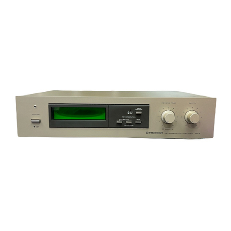
  9. Pioneer SR-9 User manual

Pioneer SR-9 User manual

to
REVERBERATIONAM
PLIFIER
MODELSR.g
COMES
IN FOUR
VERSIONS
DISTINGUISHED
AS FOLLOWS:
Typ. Voltâgp Remarks
KU 120Vonly U.S.A.
model
KC 120Vonly Canada model
s110V.
120V,
22OYand240V(Switchable) General
export modol
S,fG 110V,120V
220Vand240V (Switchable) U.S,
Militarymodel
r This isthe service
manual
for model
SR-g/KLr,
KG Formodel
SR-9/S,
S/Gtypes,
please
referto page
15.
r Ce
manuel
d'instruction
serefère
aumode
deréglage,
enfrançais.
r Este
manual
deservicio
tra6 delmétodode
aiuste
escrato
enespafiol.
r Forcircuit descriptions,
referto the Service
Manual
for SR-303
(ART'3651.
Fl..
ADDTTIONAL
SERVICE
MANUAL .*,
1. SPECIFICATIONS
. 15
2. CONTRAST
OFMISCELLANEOUS
PARTS. . . . 16
3. SCHEMATICDIAGRAM ,......17
2
2
3
4
5
7
I
12
13
14
14
14
CONTENTS
1.
2.
3.
4.
5.
6.
7.
8.
9.
10.
SPECIFICATIONS
.
BLOCK
DIAGRAM
FRONT
PANEL
FACILITIES
PARTS
LOCATION
ELECTRICAL
PARTS
P.C.
BOARD
CONNECTION
DIAGRAM
SCHEMATIC
DIAGRAM
EXPLODED
VIEW
.
PACKING..
ADJUSTMENT
RÉGLAGE
AJUSTE
....
() rrloNeeFl'
ORDER
NO.
ARP
-O55-O
ltlGtNEEFl ELECTFIGINIC CGIFIFGIF-ATIGIN 4-1 ' Mesurc 1-chomê' Mesuno-ku' Tokvo 15€' JBp€n
u.g. Ffcr\frEF --="".o[.êâ,=COeeeatql eS-ôxroea DnivEi Mænæhie' New JeÉev O7O74' '.,=.A'
:Ë.,"#"*#,ËîGg'oïJ*:g:;z:L:"ffi.il"ff l3:3::1""i"'vic,oni631EE'A@'Ëne'|ie
YU o DEC.1981 Printed
in lapan
"",-.. èjd,d,4h
4. PARTS LOCATION
r Front
Panel
View
Front panelassembly- '
ANM.123
Push
knob
A (POWER
AAD.178
Push
knob
B
iiÂPÊ r,rronlroR,
REvERBERATION)
AAD.179
r FrontViewwith Panel
Removed
LED
assemblY
1
GWX-303
A ** Push
srrritchIPOWER)
ASG-215
r Rear
Panel
View
lop cover
ANE.376
Terminal
(REVERB,
TAPE)
AK8-063
Push
knob(ATTENUA
AAD.OI5
r TopView
[ * Ponrærtransformer
(12OV)
ATT.595
(KUI
ATT-736lKCl
Lamp assembly
AWX-lA0
Switch assemblY
GWS-185
NOTES:
o Porfs without part number cannot besupplied'
o,IheImorhfoundonsomecomponentpartsirtdicatestheimportanceofthe
safety factor of the part. Therefore, whenreplacinl' be sureto use parts of identical
designation.
!
Knob
(REVERB
TIME,
DEPTHI
AAB.291
ff Push
(TAPE
MONITOR)
ASG-214
** Variable
resistor
with switch
IBEVERB
TIME)
ACV-508
* Variable
resistor
(DEPTH)
ACV-I25
3€ang
push
TREVERBERATIONI
ASG-212
I AC sockettAC OUTLET)
AKP.O38
Strainrelief
AEC-327
'[ AC Povrær
cord
ADG-O52
Reverberatlon
ææmbly
GWM-13i1
I
(
t
a3.
FRONTPANEL
FACILITIES
O)
PowERswrrcH
Powerissuppliedto the modelSR-9
whenthisswitch
isdepressed.
The power indicator comeson assoonas
thepower
is
supplied.
€) PowERrNDrcAToR
This comeson assoonasthe SR-g's
powerswitchis
set to ON to indicatethat power is beingsupplied.
@nevenBERATtoN
EFFEcTtNDtcAToR
Thisdisplaysthereverberation
effect
graphically.
When
the reverberation
time is increased
(the reverbtime
control is rotatedclockwise),the winking intervals
of
the light arelengthened.
Converæly,
whenthis tirne
is
reduced (the reverb time control is rotated counter-
clockwise),
these intervalsare cut short. Also, the
lightingareaincreases
in proportionto the sizeof the
reverberationcomponents.
This area is increased
as
the depth control is rotated clockwise.The reverb
time anddepth controlsare
æt to the preferredposi-
tion as
you checkout the reverberation,
but if the re-
verberationindicator'scircle of light remainson the
display, it means
that the reverberationcomponents
are excessive(too much of an echol Use this as a
base
for adiustments.
@)
REVERBERATIONON
SWITCH
Depres this svvitcft
to produce a reverberationeffect
with the signals
fed from the REVERBERATION
INPUT jacks. The reverberation
effect indicatorwill
come on, and signals
featuring
a reverberation
effect
only will be fed out from the model
SR'9'sOUTPUT
jacks.
€) REVERBERATION
ON-RECORDING
swtTcH
Depres this switchwhen recording
a program
souroe
whosesignals
featureareverberation
effect onto atape
in a deck connected
to the mode
SR'9's
TAPE iacks.
Thiswill allowsignals
with the reverberatingsound
to
be made
availabe
from both theSR-9's
OUTPUT
iacks
and
theTAPE REC
jacks.
@
nevenBERATroNoFF
swrrcH
Depress
this switchto cut off the reverberationeffect.
Thiswill allowsignals
without areverberatingsound
to
be madeavailable
from both thesR-9's
OUTPUT
iacks
andtheTAPEPLAY iacks.
NOTE:
The rcverberation on $titch, the reverberation on-recording
switch and the reverbration off swiæh are all couplel. When
you depres one switch, make stre that all the odnæ arc re
leaæd.Donot depressmorc thanoneswitchat a time.
e)repeMoNtToRrNDrcAToR
This comeson when the tape monitor switch is de-
presed.
@ TAPEMONTTORSWTTCH
Depress
this switch to monitor the sound on the tape
as it is being recordedor when playingback a tape
using
a tapedeckconnectedto theSR-9'sTAPE
iacks.
(The
tape
monitor indicator
comeson.)
o REVERBT|ME
CONTROL
Thisis
used
to adiust
thedelaytime.
The reverberation effect becomesmore pronounced
whenthiscontrol isrotatedclockwiæas
you listen
to
thereproduced
sound.
Listento thesound
andthenset
this control for the optimum effect.Selection
canbe
made between two types of reverberationwith the
model SR-9 by pushing
the reverbtime control or
pulling it out. Pushing
the control gives
EFFECT 1
(longer reverberationtime) and pulling it out gives
EFFECT2 (one
reverberation
component).
@
oeprxcoNTRoL
This is usedto adjustthe depth of the reverberation.
When it is set to the '0' position,only the original
sound will be heard. The reverberation
component
increasesas
this control isrotated
clockwise.Listen
to
the soundas
it reverberates
andadiust
thiscontrol to
theoptimumPosition.
C0a{o ɀta
1.
SPEC|FICATIONS
Reverberation
AmPl
ifierSection
lnput(Sensitivity/lmpedance).. . .. 150mV/50kO
(at
1kHz,
DEPTH
volume:
0)
Frequency
Response . . 5Hz
to T0kHztldB
(at
DEPTH
volume:
0)
Total Harmonic
Distortion Les than0.05%
(at
lkHz,1V,
DEPTH
volume:
0l
Maximum
lnput
Level i", riHr,'iv,
ôÈpiH
"r,L,.,.."r'oÏ
sisnal
to
NoiseRatio ' ' '(;iiv;#piH;;r".S
Reverberation
Time . . . 0 to 3 sec
(atEFFECT1,400H2)
25msec
to 1OOmsec
(atEFFECT2,4OOHzl
Output(Level/lmpedance). ..150mV/1kQ
(at
lkHz, DEPTHvolume:
0) I
ql s5
tl
@
lAPE
I
L FEC
OUlPUl
INPUT
s3-6
2. BLOCKDIAGRAM
TPLAY @-{ sz'l
ÏAPE
L REC
ouTPuï
lræwl
INPUT
li5ùVl
Lch
Rch
'-euv @-<
swrïcHEs
sr ÀlrENUAloR OdB - -6da
s2 ÎAPE MO{|TOR OX - OFf
53 REVEREERATIOdON OT - OFF
S FEVERAERÂTION
ON IR€COROING} OX - OFF
55 REVERBERÂÎION OFF O{ - OfF
s6 ÉFFECÎ t-2
SZ POWER ON - OFF
Tha ond..liô.d i.dicorat In. rrlrch porillon
Miscellaneous
Power
Requirements AC120V,60H2
Power
Consumption 13W
Dimensions . 420(W)
x 99(Hlx 336(Dl
mm
16'9/16(W)
x 3'718(H)
x 13'1/4(D)
in
Weight
(withoutpackagre) 4.3kg
(9lb 8oz)
Furnished
Parts
Connectioncordwithpinplugs ...-'.2
Operating
instructions I
NOTE:
Specifications and the design subiect to possible modîfication
without notice due to improvemenæ.
s4.2r lrr L- t--fi- 7-r ..^ lr.,
>J"J Mrxrxc
arP
2
ets
tn læL-ai
7nrol!.'oJÆft -w/ttMrER
' 1E
COIMESSOR DETEOOR
r20v
toow uÂx
I
v
I
I
o
oçOe
-Xrf\9
(
l)ÂFsvo3-'l tOg -Xrt19
r,r.y(
zj31
C
N
)001
028
- ap9
È
rs
t
c
Bpo
I
1rv I
I
tr-
@AVld
e
@3fu
o
rÈ\
vtnatno -
t)
@INdNI
o
c
E
rtttttl
ltttl
ttttt
iii::
trltf
;iiii
-v.trô ar eô eô rf
c999
cû/oL, r,oo
o
I,'ol ,"1 llgl s,
/
tr ",iT Ti'' -
tltl
il tl
9
LçZ)SZ
u
l
V
çzô ,zo Lt) Ê
6O 8b 610
gÊl- n,t\g Â,ssy
+7
Y
ilo gzD
olb
LZô OZ0
zr0
o
,I
I
.'of:^ oO
" ,(t)
,irYi.,, )i
"Ë eo
! (E) vÇ
çzç )3v
I
c
-a
ro zD sD r0
t
II
tgl- xnv
Â.ssy
4y1y1
l tvu9vlo NolrclNNOC OUVOg
'C'd'9
to5. ELECTRICAL
PARTS
NOlES;
c When ordering resrsfors, first convert resistancevalues into code form as shown in
the following examples.
Ex. 1 When there are 2 effective digits (any digit apart from O), such as 560 ohm
and 47h ohm (tolerance is shoun by J = ïVo,and K = 10Vo).
560dr 56xI1t 561 .. .. RD%PS
t5@][]/
47ha 47x103 473.. .. RD%PS
EDUpNJ
0.5a
IO 0R5.. ..... RN2ITOEEK
010.. RsrPoDElK
Ex. 2 When there are 3 effective digits (such as in high precision metal film resis-
tors).
5.62hsr 562 x 100 5621. . . . RNV4SR
EE]trtrr
c The A marh found on some component parts indicates the importance of the
safety factor of the part. Therefore, when replacing, be surc to uae
parts of identical
designation.
c For your Parts Stoch Control, the fast mouing items are indicated with the marhs
U* and *.
** GENERALLY MOVES FASTER THAN *.
This classification shall be adjusted by each distributor because it depends on model
number , temperature, humidity, etc.
Miscellaneous
Parts
Mark PartNo. Symbol& Deccription Mark PartNo. Symbol& Dorcription
GWM.133
GWS-185
AWX.164
GWX.3G'
cwx-304
OTHERS
Mark PartNo.
Rarerberation
æsembly
Switchassembly
Lampassembly
LED
assambly
I
LED
æsembly
2
Symbol& Dæcription
*
*
a*
*
1S2076
(1S1555)
MZ-o75
(Wz-07s)
10E2
(srB01-021
MZ-157
lwz-1571
D1-D4, D6-D10
D5
Dl
1,
D12
Dî3,
D14
T1A*
A*
,{\
^
^
ATT.595
ATT.736
RD/PSF 2R2J
AKP.OOS
ADG.O52
Power
transformer
(1
2OVl
(KUl
Power
translormer|120V)(KC)
Carbon
falmresistor
CAPACITORS
M.rk Part No.
ACsocket
(AC
OUTLETI
AC powercord
SYmbol
& Decription
CEANL
2R2M
50 C1-c4
cEA l(x)P16 C12
CEANLol(M50 C20,C21,C23-C25,C30,C31,C40
cEA 101P
16 C22
cEA 470P16 C28,Cæ, c45, er6
Reverberation
Assembly
(
GWM-Î
33)
SEMICONDUCTORS
Marlc Part No. Symbol& Dæcdption
**
**
**
ff
2SC1919
(2SC1400)
2SA7265
(2SA7501
sPC4558C
lNJM4558OX)
MN3008
2s,C22æ
pPD4069C
25K30A
{25K34}
2SC2575
(2SC945A)
2SC1384
25A684A
01,
02,06,o10,ot2,o14,
o15
03.04,07.og,01I
05,
016,O19-O21.
O29
08
013
017
018
o.22-426
o.27
028
CEANL
3R3M
50
CEANL
6R8M50
cEA471P35
cEA101P
25
cEA221P16
caMA222J50
coMA 472J
50
coMA332J50
coMA102J
50
coMA 682J
50
coMA 153J50
coMA223J
50
ccDsL221K50
ccDsL330K50
ccDsLl8lKs0
ACG-009
c32,
C33
c38
c41,C42
c/,3,c4
c47,Cæ
c5,
c14
c6,
cl5
c7,cl1,
C16,C19
ca,c17,
c27
c9.cl8
cl0,cl3
c36.C37
c26
c34,C35
c39
C49,C50 Ceramic 0.047llæV
**
**
SWITCHES
Mark Part No. Symbol & Dæcription
sl Push
{ATTENUATORI
S2 Push
(TAPE
MON|TORI
53 3-gang
push
(REVERBERATIONI
*rt ASG-IEO
** ASG-214
** ASG.212
RESISTORS
Note: Whenordering resistors,
conuerttheresistance
ualue
into code
form,andthenrewritethe
part no.asbefore.
Mark PartNo, Symbol& Dercription
** ACV-508
* ACV-125
* ACP-056
RDY.PM
trtrOJ
RS2P
otrtrJ
A RDT.PSF
trtrEJ
BOy"PS
otro J
OTHERS
Mark Part No.
VRI (56) Variable
reslstorwith switch
(REVERB
TIME)
VR2 Variabte
resistor
(DEPTHI
VR3 Semifixed22k-8
R1-R114,R12(FR125,
Rl29-R133
Rl15-R1
17,
R126
R118,R119
R127,R12A
Symbol& Dccription
AK8.063
LampAssembly
(AWX-1641
Mark Part No.
Terminal
(REVERB,
TAPE)
Symbol& Decription
ff 4E1-1gg
AEC-558
Switch
Assembly
(GWS-1851
Mrk PanNo.
PLl-PLg Lamp
8V 70mA(bar-typel
Nylonrivet
Symbol& Dccription
l\ ff ASG-215
ACG-û)9 s7
c51 Push
switch
(POWERI
Ceramic
capacitor
0.047/150V
LEDAssembly
I (GWX-303)
Mark PartNo. Symbol & Dercription
* AEL-325
ABA.065 Dl5 LED
(POWER)
Screw3x6
LEDAssembly
2 (GWX-3041
Mark Prrt No. Symbol& Dccripdon
* AEL-324
ABA.065 Dl6 LED
(MONITORI
Screw
3x6
I
I
I
I
o
-)TE:
loleronce uî1935 0làêryiso nol€d
tl t voltoge lV) unlars ofh€ei9€ nored
'ui volloge 13
5OV €rcopl €laci.otytic
t l5OnV output ( I kHz )
ol no input .ignol
!o inpul ti9nol
ma coftponenl Dor13 indicola6 lha
, loclor ot lh€ porl Tharefo.ê, wh€n
-f9orts of idenlicol da3ignolion
rc indicated semiconductors are representatiue ones
iy. Other alternatiue semiconductors may be used
and
? lkted in the parts list. 2SCt919
25A7265 uot
tlo
2slg2575
External
Appearance
of TransistorsandlCs
2SC1tl00
25A750 Type No
(cl
(U' UNSWIÏCHE0
I dB
- -6dA
ON - OFF
ON ON
- OFF
ON
(RECOROING)
ON
_OFF
OFF ON - OFF
2OFF
a
Jicol€s th€ swilch poirlron
I
|
20v
roowMAx
i LEO Ass'v fi )
t-
,ER' I GWX-3O3
--J25
|
7
pFC4558C s a
N$r4558Dx
.nn44
W
rI- Ass'y 6WS-185
POWEF
57 asc-2t5
I
8
B
2SA684A Sultix
hre
Lot No
rrPiC4(l69C
-
-
LAMP Ass'y AWX-164
1O.ADJUSTMENT
1. Set
the ATTENUATOR switchto 0dB.
2. Press
the REVERBERATION ON switch (i.e.
switchon).
3. Check that the TAPE MONITOR switch is
OFF.
4. Pull the REVERB TIME control out into the
EFFECT 2 position.
5. Turn the REVERB TIME control until the fre-
quency measured at the TP1 terminal reads
2OkHz.
6. Connect the oscilloscope
to the TP2 terminal.
7. Apply a 400H2, 150mV signalto the input ter-
minals.
8.
I
7.
8.
1.
2.
3.
4.
o.
6.
7.
8.
a
10. REGLAGE
Placer le commutateur de I'atténuateur (ATTE-
NUATOR) surla position OdB.
Appuyer sur I'intermpteur d'enclenchement de
la réverbération (REVERBERATION ON).
Vérifier que le commutateur de contrôle
d'enregistrement (TAPE MONITOR) soit sur la
position déclenchée
(OFF).
Tirer la commande de durée de réverbération
(REVERB TIME) surla position "EFFECT 2".
Tourner la commande de durée de réverbéra-
tion (REVERB TIME) jusqu'à ce que la fré-
quence mesurée à la borne de TPl soit de
20kHz.
Raccorder I'oscilloscope à la borne TP2.
Then adjust VRg so that the waveform shown
in the oscilloscope
is symmetrical the horizon-
tal axis.
Appliquer un signal de AOOHz,150mV aur
bornesd'entrée.
RéglerensuiteVR3 de façon à ce queI'onde
apparaissantsur I'oscilloscope
soit symétrique
parrapportàI'axehorizontal.
Aplicar una sefral de 400H2, 150mV a los
terminales de entrada.
Luego, ajustar el VRB de modo que la forma de
onda mostrada en eI osciloscopio seasimétrica
al ejehorizontal.
TPr--;-
É'---rin
vt------vdV V
TPl->
f*rà à
c----Jg9
10. AJUSTE
1. Poner el atenuador (ATTENUATOR) en la
posiciônOdB.
2. Presionar el intemrptor de reverberaciôn
activada (REVERBERATION ON) (conectar el
intermptor).
3. Comprobar que el monitor de cintas (TAPE
MONITOR) esté
enla posiciônOFF.
4. Tirar haciraafuera del control de tiempo de
reverberaciôn
(REVERB. TIME) dejândolo en
la posiciônEFFECT 2.
Girar el control de tiempo de reverberaciôn
(REVERB. TIME) hasta que la frecuencia
medida en el terminal TP1 indique 20kIlz.
Conectar el sociloscopio al terminal TP2.
5.
6.
1
EXPLODED
VIEW
)-b
Parts
List
Mark No. Part No.
NOTDS:
o Parts
without part number cannot be
supplied,.
o The I marh found on some component parts indicates the importance of the
safety faetor of the part. Therefore, when replacing, besure to use
parts of identical
designation.
o For your Parts Stoch Control, the fast moving items are indicated with the marks
*t ond *.
** GENERALLY MOVES FASTER THAN *.
This classification shall be adjusted by each distributor becauseit depends on model
number, temperature, humidity, etc.
Dascription Mark No. Part No. D€scription
26.
27.
28.
29.
51.
52.
53.
#.
55.
56.
57.
58.
59.
60.
Ar
/i\
1. ANE-376
2. VCT30P060FZK
3. AAD-I78
4. ANM-I23
5. AAD-179
AAB-291
AKP.O38
ATT.595
ATT-736
9. Awx-164
10. ADG-Os2
11. AEC-327
12. AAD-015
13. AEC-351
A 14. RD%P9F2R2J
15. VCZ30PO60FMC
16. VBZ30P100FZK
17. VTZ40P080FMC
18. VCZ30P080FMC
19. VTZ40P160FMC
20. VBZ30P060FMC
21. VCZ3oP1q)FMC
22. ABA-115
23. MTZ3oP100FZK
24. VMZ30P060FMC
25. ABN-024
9. PACKINI,
Top cover
Screw
Push
knobA
Front
panel
assembly
Push
knobB
Knob
ACsocket
(AC
OUTLET)
Power
transformer
(
I2OV){
KU)
Power
transformer(
120V)lKC)
Lampassembly
AC powercord
Strainrelief
Push
knob
Foot assembly
Carbon
film resistor
Screw
Screw
Screw
Screw
Screw
Screw
Screw
Screw
Screw
Screw
Nut
GWM-133
GWS.185
GWX-303
GWX-304
Reverberation assembly
Switch assembly
LED assembly1
LED æsembly 2
Rubber A
Sideframe
Terminal strip 2P
Transformer base
6.
7.
8.
RubberI
Wiresaddle
Subfanel
REI assembly
Rearpanel
61.
62.
63.
64.
65.
66.
Bottorn plaæ
Holder
Extension bar
PartsList
Mark No. Part No.
1. AHE-01
1
AHE-Ol8
2. AHA-310
3. ARB-464
4. ADE-005
Description
Packing
cæe
(KUl
Packingcase
IKC)
Side
pad
Operating
instructions
Connection
cord
13
4
Ql3
- 15,16
(t/Z)
VOLTAGE
CONTROL
AMP
{",," A q1
1 RESISTORS:
Indicatod in
O, I
k:kO, M MO
2 cÂpactToRs ,
!ndjcotêat in copa
p pF lndicofi
copocitor
3 VOLIAGE,
CURR
I Vl Siqnof vr
-uv votlo
+ma I DC curr
4 OTHERS:
@:Adjusting poil
The A mork fou,
rmportonce of th
replocing.
be surs
swtTcH€S
S I ATTENUA'I
S2 TAPE MO
S
3 R€V€RAER
S4 REV€RAER
S5 REVERSER
56 EFF€CI
S7 pOr,V€R
Th€ und€rti
A"'
Q27,2a
REGU
LATOR
Q16
(
2/2 't
I
NVERTE
R
Q
r3 25C2259
-G
ar4.r5
zSCtgtg
-o
Q
16 p
pC4SSBC
R7t et8
39T BUFFER
AMP
Qt7 CLOCK
GENERATOR
orz !pD4069C
ar8 zsK3OA-Y
429 U/2)
DETECTOR
ai9 !zt ,,rpC455BC
QzO
(r./z)
MtX,/
DEI ( -')
Dr-
4 ls
2076
05 MZ-o75
06 ts207
6
R7a
200t R€r
200r
Dtr.t2 loE2
ol3,
l4 MZ_1O7
q21 | L/2 |
MIX ,/
LIMITER Q22*26 25C2575-F
Q27 eSCt3O4-R
o2a 25a6A4A_R
Q2e qqC4SSAC
) INVERTER Q21
(2/2) Mtx
/ DEl (+l
Q2?,23
BUFFER
AMP Q29(
2/? )
INÏERFACE
2SCr4{rO
2SA750Type No
External
Appearanæof
Translstors
andl0s
Type No
I
I
I
cr,ndur;tr,ts
arc
rcytzsrlntrltiue
ones
i.ue
semiconductors
may
beused
and
Ilist.
i€ not€d
isa noiod
rt€CtrOtyl
ic
as tho
ùo, wi€û -
I-l
2SC9.05A
I - -6dg
N _ OFF
1 ON
- OFF
(R€COR0ING)
ON
-OFF
F ofv - oFF
rres th€ 3witch ooiilion Lot No
hre
pFCttSSgC 5 a
NJr,ttt5s8DX
.l-[,44
&ilM/ Sullix
ACPOWER
CORD
ADG-O52
^
zit
utswtTcHEo
16'y GwS-185
LAMP Ass'y AWX-t64
MN3(xt8
t20v
loow MÂx
i LEDass'y
(
i )
r) | Gwx-3o3
325 I
6
! | P12,4,6,8
J L_irr%!l
pF&t069C
moy vafy
POWER
asc
-2r5
vI
I
o
I
uôrsAp ur sluaua^o/dur ol anp
nl90 aql lnq 'uoJ6Drp crloûoqcs clsoq aql sr srql
JO- NO
rôW(
---+
;. ogt/Lvoo I
tçc
___J
I HC.tl,tlS
;oi:i;- - -l
^uoz ^€ |
z',ç'€'rtd I
t3v
fod )
çr0
-I
,"V Ira\r/ 8il8V
uo.tv'rn93È
ez,Lzo
lu! peullrepun
eql
-NO U3iOd zS
l- | -!f,31j3 95
NorM3Sàf^fU 9S
NOtM3€U3^3U rS
NO|lVU3SU3^3A e S
aottNon 3dv_t- z s
: uotvnlttly l s
sSHCl-tMS
I osn o+ eJns
oq ôuroolde/
Ilelos eql lo scuol/odul
loÊuo puno) frDu V grl.l
tutod 6ut$nlgy:qà
: SÈtH1O
u lD lu€rrnc co vu+
D(^) eôolto^ CO : f]\
lo e6otto^ tou6rS li----l
: -tN3BUn3 39V1-1O^
)olttodDc
roqlra uortocrpul ld :
d
'lrl ) I+rcodooùr polDcrpul
i S8Oll3VdVf,
UW,W'Ur:l
lDg'-'t^t/t 'o ur peto.rpul
saolsts3u r dwv ]oul-Nof, 39T110^
(Z/l)9r'9t-Êlb
o
0ato
tuo
lu
)N v
I
I
u3^
ruo dr,ùv
r
9Z
- VZb
Lçl-ZW tl 'ç
rc
Z3Ol zl rlc
(
+
) 130 / Xllt (Z/Zl rZO
33V3U3LNl dt/!VU3lln€
(Zlt?l6zè Êz'ZzO
cggstcdrr 620
u-vtggvsz 8eo
u-tsÊr9s? Lzo
l-92çzcsz ez-zei u3Lrt{r-l
/ xrhl
( z/1| tz\
(-)L30lxtw
(z/
t,
ozo
OgçgtCdrf rz+
9ZOZSI s0
gLO-zur ç
o
9ZOZSI
t -ro
^
-voe
rsz 8to
C690ùOdrf rto
uol-vu3N39 yf,OlJ Zlb
'".","j+ l:l? irzl I
- "no
C999tCd tf stb
9-6t6lCSZ st'ttb
9-69ZZCSe er
0
u3fu3 ^NI
(
z/z, 9tÔ
Izt
tOÊ
-X,vl9
(z) r,88V
O3-1
!-;;.F--1
I
uortNo{ ) t
il -J
II
j'
INdN I
I
tôdtno
I
lI
j'
--'l
I
I 3dV1
rl
lv'td J
ros ^-,.
z-za\ "'!-'
ro9
t-zaA
oç,/Êç
zrc
I
I
I
i| 6a-c'l
J.ndN
I
l_
I l^u6rl
rndrno
i
zt -
AJv
rdfo zt^
uoss3udnol
(z/?l 90
r9ç
çÊrd L.,+'
-
0€u
-
!.i:J
I
l-rs z-€s
9ZOZSt or^
r.o
9-6l6lCSZ zr'olo
9
-SgZZVSZ Ir'6ô
ç-rs e-Ês z-ts
dl{v u3Jjns
r-lb
sooÊNW
9
-
59ZZVSZ
9-61613SZ
0899ûCdft
9
-
59ZZVSZ
9
-
616
rrSZ t Êb zr?'9sv ilollvÙ3€u3^3t c't'€s
Z'tO tlz'9sv uolliol ldvt ?s
O9l_gsv Irv Is
dnv gNrxtn
(
?/1)ç0
0ss lol
8D rÊu
çÊl
-
lt/Yr9 {.ssv Notrvu3gu3^3u
ltvuovlo cllvl llHcs 'z a
I
v
t
t
o
(DrqoNEEFl'
REVERBERATION
AMPLIFIER
I The basic
performance
of the S and S/G types are same
asthe KU, KCtypes.Thisadditionalservice
manualis applicable
to tte S andS/G types,pleæe
referto the KU, KC typesservicemanuat
(see
paç
2- 141with
exception
of thissupplement.
1.SPEC|FtCAT|ONS
Reverberation
Amplifier Section
Input(Sensitivity/lmpedance)..
. .. tbOmV/SOkO
(at
lkHz, DEPTH
volume:
0)
Frequency
Response 5Hzto TOkHztldB
(at
DEPTFI
volume:
0)
Total Harmonic
Distortion . . . . Less
than0.05%
(at
1kHz,1V,
DEPTH
volume:0)
MaximumlnputLevel .....2V
(at
lkHz, tV, DEPTH
volume:0)
SignaltoNoiseRatio ....gOdB
(at
1V,DEPTH
volume:
0)
Reverberation
Time . . . 0 to 3 sec
(at
EFFECT
l,400Hz)
25mæc
to 100msec
(atEFFECT
2AOOHzl
Output(level/lmpedance) ..l50mV/lke
(at
lkHz,DEPTH
volume:0)
Miscellaneous
Power
Requirements ...I1OV|12OV|Z2OV124OV
(switchable),
50/60H2
PowerConsumption ......13W
Dimensions ..... 42OlW)x99(H)x336(Dlmm
1ô-9/16(w)
x 3-7l8(Hlx13.1/4(D)
in
Weight
(withoutpackage) . . . . . 4.3k9(9 lb8oz)
Furnished
Parts
Connectioncord
with pinplugs
Operatinginstructions
Specificationc and the design aubject to pæeible modifica-
tion without notice due to improvemenb.
2
1
o
o
Mark Symbol & Dcrcription PartNo.
KU typo Stypo S/G typc
a*
A*
A**
A
Povwr
transformer
(120V)(KC)
Power
transformer
(110,
120,220,240V1
Resistor
58 Linevoltôgoselector
AC povwrcord
Screw
(Linevoltaç selector)
Operating
instructions
Operation
instructions
Packing
case
Spacer
ATT.595
RD%PSF2R2J
ADG.O52
AR8464
AHE.OI
I
ATT.596
AKX-063
ADG.046
VM23OPO6OFMC
ARE471
ARH.Og2
AHE.Ol
1
ATT.596
AKX-063
ADG-046
vMz30P60FMC
ARE471
AHE-OI6
AHB-102
2. CONTRAST
OF MISCELLANEOUS
PARTS
e
a
I
A.o-l'
56l trzwl
NOTE:
The indicated semiconductors are reprcsentatiue ones
only. Other alternatiue semiconductors may be used and
are listed in the parts list.
-
-
r RESTSToRS'
Indicoied inA, V4W. !5% tot€ronc€ unt.sÊ other*ile noi€d
krkO, M,Mn
2 CAPACITORS
:
Indiêoled in copocily (!F) / vollog. (V) unto3s
ofhewis€ noted
p,pF Indicolion wifhout voltog. ls 5OV 6rc.pt .t.ctrclyllc
co
poct
lor
3 VOLTA6E.
CURRENT
:
El , Sienot votfoge ot lSOhV output ( I tHz )
-È , OC votroge
I V) ot no Input .ignol
+mA : DC currafil ot no inpul signol
4 orH€RS j
@tAdiu.iing point,
the 2\ mork found onlom€ conpoôonl ports indacotas tha
imporlonce ol iho 30loly toclor ot lha port Thorefor€.rhan
replocing,
b9 sur€ to usa port3 ol idanticol dasiondlion
sw I
lcHEs
S I ATTENUAÎOR OdB
- -6dB
52 ÎAPE MONITOR ON _ OFF
s 3 REVERBERaTTON ON g_l! - OFF
S4 REVERBERAÎION
ON (RECOROING}
ON
-OFF
S5 REVERB€RAIION OFF 9A - OFF
56 EFFECT I _2
s7 POW€R Oil - OFF
ss LINE VoLTAGE sELE-croR ?JgL-24ov -t2w -fiov
Th€ und.rlin.d Indicot.3 th- atttch 9o!ition
uiswrTcH€0
ux rooï
A' orr-r""
L_ or.j.æ !
I PL1,3,5,7
z{ov r20v
220V ilOV
SA:Lli€rcLTAG
SELEClOR
GRY AKI.O63
A
I P12,4,6,8
L__il.rsjJ
L-:xJ-"rlJ
SWlTCtl As6'y GWS
-185
!-;.--;";"-l
OO47/tæ S? ASG-2t5
This is the bosicschemolic diogrom,bul lhe ociuol ci/cuil
due to improv€menls
in dssign
I
8
ac
rrov
l20v
220V
240V
5016OHr
AC PO|EÊ CORD
^DG-
046
7
t50
moy vory
3
2
to3. SCHEMATICDIAGRAM
REVERBERATION As6'y GWM -t33
t-
€FFSCT2 o
s6
s2 TAPÊ XOiTTOR ASG-2r4
s3,a,5 R€VERA€RATTO{ASG.2t2
I _ ÂELr24 !
LED
Ass'y
(2)
GWX-304
2SCr9t
9-G
?s
47265
-
C
,rPC4558
C
25Cr9l9
-G
2SA7265-
G
MN
3008
BUFFER AMP
R5 2701
Qr,2
Q3.4
Q5
Q6
Q7
Q6
+.,"i
I
Lch
I
L
I
OUTPUT
lilo.vlI I
I
NPUT
FsiNl
s4-2 Rt Z2r
o
o
R7
2?Or
R8
270\
c2

Other manuals for SR-9

2

Other Pioneer Amplifier manuals

Pioneer sa-5200 KU User manual

Pioneer

Pioneer sa-5200 KU User manual

Pioneer PHA-M70 User manual

Pioneer

Pioneer PHA-M70 User manual

Pioneer GM-D8601 User manual

Pioneer

Pioneer GM-D8601 User manual

Pioneer GM-A5602 User manual

Pioneer

Pioneer GM-A5602 User manual

Pioneer PRS-X720 User manual

Pioneer

Pioneer PRS-X720 User manual

Pioneer GM-D8601 User manual

Pioneer

Pioneer GM-D8601 User manual

Pioneer GM-X642 User manual

Pioneer

Pioneer GM-X642 User manual

Pioneer SA-7800 User manual

Pioneer

Pioneer SA-7800 User manual

Pioneer GM-X424 X1R/UC User manual

Pioneer

Pioneer GM-X424 X1R/UC User manual

Pioneer GM-D9705 User manual

Pioneer

Pioneer GM-D9705 User manual

Pioneer ND-G500XS User manual

Pioneer

Pioneer ND-G500XS User manual

Pioneer PRS-D420 User manual

Pioneer

Pioneer PRS-D420 User manual

Pioneer GM-X962 User manual

Pioneer

Pioneer GM-X962 User manual

Pioneer GM-H200 User manual

Pioneer

Pioneer GM-H200 User manual

Pioneer Elite A-20 User manual

Pioneer

Pioneer Elite A-20 User manual

Pioneer A-300R User manual

Pioneer

Pioneer A-300R User manual

Pioneer A-447 User manual

Pioneer

Pioneer A-447 User manual

Pioneer GM-X904 User manual

Pioneer

Pioneer GM-X904 User manual

Pioneer M-AX10 User manual

Pioneer

Pioneer M-AX10 User manual

Pioneer SA-510 HE User manual

Pioneer

Pioneer SA-510 HE User manual

Pioneer GM-A6604 User manual

Pioneer

Pioneer GM-A6604 User manual

Pioneer PRS-D5000SPL User manual

Pioneer

Pioneer PRS-D5000SPL User manual

Pioneer GM-A5702 User manual

Pioneer

Pioneer GM-A5702 User manual

Pioneer SA-6500 II User manual

Pioneer

Pioneer SA-6500 II User manual

Popular Amplifier manuals by other brands

PS Audio GCC Power Amplifi er Series Owner's reference

PS Audio

PS Audio GCC Power Amplifi er Series Owner's reference

Rockford Fosgate PM600X4 Quick setup

Rockford Fosgate

Rockford Fosgate PM600X4 Quick setup

CYP CDB-6HP Operation manual

CYP

CYP CDB-6HP Operation manual

OSD Audio BLACK THEATRO X11 install guide

OSD Audio

OSD Audio BLACK THEATRO X11 install guide

Unitron Johansson 7460 quick guide

Unitron

Unitron Johansson 7460 quick guide

Bogen TPU-15A Technical specifications

Bogen

Bogen TPU-15A Technical specifications

Mark Levinson 27.5 operating manual

Mark Levinson

Mark Levinson 27.5 operating manual

Sarno Music Solutions SMS Classic Jerry Garcia Version owner's manual

Sarno Music Solutions

Sarno Music Solutions SMS Classic Jerry Garcia Version owner's manual

Audio Legion AL2500.1D owner's manual

Audio Legion

Audio Legion AL2500.1D owner's manual

Altec Lansing 828 LF SPEAKER CABINET PLAN manual

Altec Lansing

Altec Lansing 828 LF SPEAKER CABINET PLAN manual

NAD CI 8-120 DSP user manual

NAD

NAD CI 8-120 DSP user manual

Bryston SP1.7PRECISION instructions

Bryston

Bryston SP1.7PRECISION instructions

Technics SU-X520D Service manual

Technics

Technics SU-X520D Service manual

Marshall Amplification MG SERIES owner's manual

Marshall Amplification

Marshall Amplification MG SERIES owner's manual

Key Digital Chroma KD-HDMI2X4P product catalog

Key Digital

Key Digital Chroma KD-HDMI2X4P product catalog

Reloop RPA-2000 Operation manual

Reloop

Reloop RPA-2000 Operation manual

Hubbell GAI-Tronics 701-904RF manual

Hubbell

Hubbell GAI-Tronics 701-904RF manual

Snell IQAES00 Product guide

Snell

Snell IQAES00 Product guide

manuals.online logo
manuals.online logoBrands
  • About & Mission
  • Contact us
  • Privacy Policy
  • Terms and Conditions

Copyright 2025 Manuals.Online. All Rights Reserved.