VY)
PIONEER’
The
Art
of
Entertainment
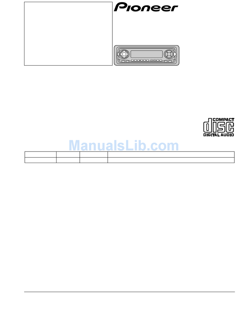
-CDX-P610
Service
Manual
Pose
The
chapter
1
of
this
Service
Manual
will
not
be
reprinted.
On
your
additional
orders,
we
may
supply
only
the
chapter
2.
For
the
chapter
1,
please
make
copies
and
attach
to
the
chapter
2
at
your
side
if
necessary.
CDOX<-PGIG
..
CcCDHoxX<X=-P6li0
UC,.EW,ES
CDX-P6IO
«.~.
@
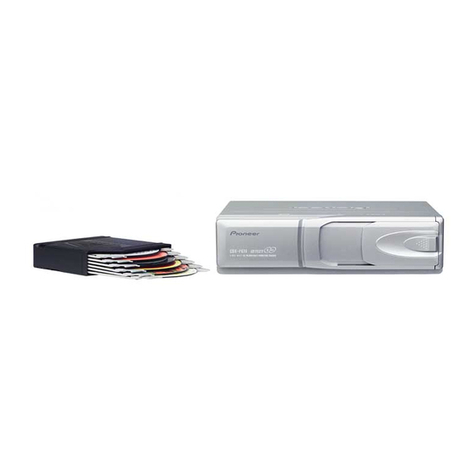
See
the
separate
manual
CX-624
(CRT1631)
for
the
CD
mechanism
description
and
disassembly.
@
The
CD
mechanism
employed
in
this
model
is
one
of
CX-624
series.
SPECIFICATIONS
General
Audio
SYStOM
css
osclccesesestecctent
eases
Compact
disc
audio
system
Frequency
characteristics
...............
5
-
20,000
Hz
(
1
dB)
Usable
discs
.........ccsccsscessesseccsssseseetsesereeees
Compact
Disc
Signal-to-noise
ratio........
92
dB
(1
kHz)
(IHF-A
Network)
Signal
format...
Sampling
frequency:
44.1
kHz
DISCO
ON
«
.ccccas.casasdescesloovscecudeevesineedalsisvcmantetsviccas
0.006
%
Number
of
quantization
bits:
16;
linear
Dynamic
range
.......scsccssceessecestenssseseeseeeeeees
90
dB
(1
kHz)
POWEr
SOUNCE?
sesccciccsscssersecccciuccevacetecdsasstescoccsssese
14.4
V
DC
Output
level
oo...
ccc
eeeeeeees
1,000
mV
(1
kHz,
0
dB)
(10.8
-
15.6
V
allowable)
Number
of
channels
..............cccccsseeessresereeeeeeers
2
(stereo)
Max.
CUFFENt
CONSUMPTION
.........ccccceseeeseeseeseeseeeee
10A
We
I
GI:
4.0
sccsseicscsavccrsascondccvecsavcastevsvaoovactenss
2.4
kg
(5.3
Ibs.)
Dimensions
............0
275
(W)
X
69
(H)
X
155
(D)
mm
[10-7/8
(W)
X
2-3/4
(H)
X
6-1/8
(D)
in.)
These
specifications
were
determined
and
are
presented
in
accordance
with
specification
standards
established
by
the
Ad
Hoc
Committee
of
Car
Stereo
Manufacturers.
Note:
Specifications
and
design
are
subject
to
possible
modification
without
prior
notice
due
to
improvements.
CONTENTS
CHAPTER
1
CHAPTER
2
1.
SAFETY
INFOMATION...
cscs
cssssseeserseneseenees
1-2
1.
EXPLODED
VIEW
000...
ese
cee
ceteeeeeeeteeeeceeeeneeeee
eeeeee
2-3
2.
OPERATIONS
AND
CONNECTION
.....000..-
teens
1-3
2.
PACKING
METHOD...
eeeessessseececceeeeceereseness
cueees
2-8
3.
DISASSEMBLY
........cscessessssssssssessecsesescancessecenesseres
1-4
3.
CONNECTION
DIAGRAM(1)......-.seessescereseseesees
cree
2-13
4.
ADJUSTMENT
0.00.
..c.cccccssssesessscesssscasececsssessseseeonees
1-5
4.
SCHEMATIC
CIRCUIT
DIAGRAM(1)...........sese
ee
2-17
5.
CIRCUIT
DESCRIPTION
....o..
ee
eeeeceneeeeeeeeereees
1-18
5.
SCHEMATIC
CIRCUIT
DIAGRAM(2)...........20.
e+
2-20
6.
EXPLODED
VIEW
PARTS
LIST
.....0....
ee
eeeeeeeeeees
1-39
6.
CONNECTION
DIAGRAM(2)....0...
ececeseeseeeseeene
oes
2-23
7.
ELECTRICAL
PARTS
LIST
ue
cece
ces
stetseseeeeeeees
1-42
7.
BLOCK
DIAGRAM
...0....cceceeceeecseseeseetseceeceeceeesees
ere
2-25
PIONEER
ELECTRONIC
CORPORATION
4-1,Meguro
1-Chome,Meguro-ku,
Tokyo
153,Japan
PIONEER
ELECTRONICS
SERVICE
INC.
P.0.Box
1760,Long
Beach,California
90801
U.S.A.
PIONEER
ELECTRONICS
OF
CANADA,
INC.
300
Allstate
Parkway
Markham,Ontario
L3R
OP2
Canada
PIONEER
ELECTRONIC
[EUROPE]
N.V.
Haven
1087
Keetbergiaan
1,9120
Melsele,Belgium
PIONEER
ELECTRONICS
AUSTRALIA
PTY.LTD.
178-184
Boundary
Road,B8raeside,
Victoria
3195,Australia
TEL:[03]580-9911
©
PIONEER
ELECTRONIC
CORPORATION
1994
cease
soak
Ganda
