manuals.online logo
Brands
  1. Home
  2. •
  3. Brands
  4. •
  5. Pioneer
  6. •
  7. CD Player
  8. •
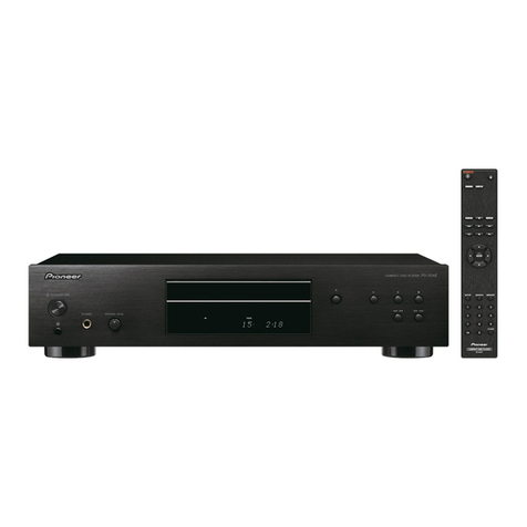
  9. Pioneer PD-S605 User manual

Pioneer PD-S605 User manual

This manual suits for next models

2

Other Pioneer CD Player manuals

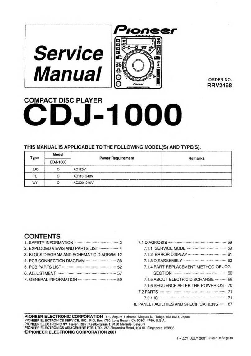
Pioneer CDJ-800MK2 User manual

Pioneer

Pioneer CDJ-800MK2 User manual

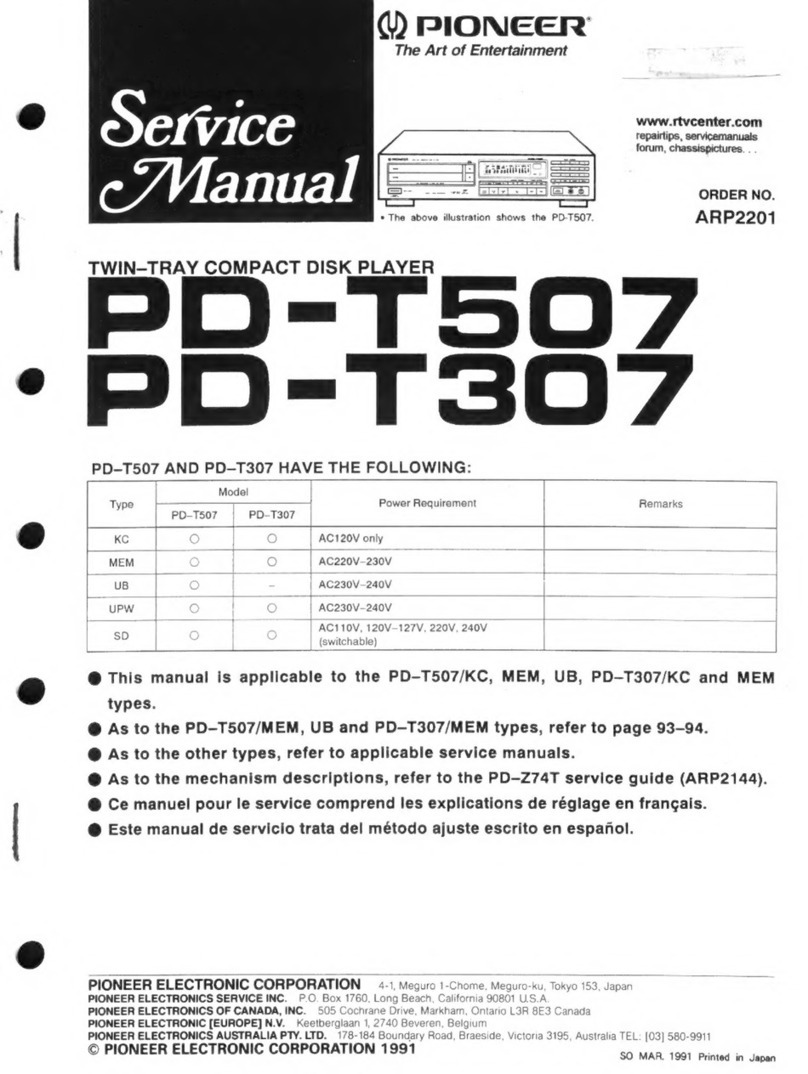
Pioneer PD-TM3 User manual

Pioneer

Pioneer PD-TM3 User manual

Pioneer CLD-2090 User manual

Pioneer

Pioneer CLD-2090 User manual

Pioneer PD-S602 User manual

Pioneer

Pioneer PD-S602 User manual

Pioneer CLD-S360 User manual

Pioneer

Pioneer CLD-S360 User manual

Pioneer CDX-FM121 User manual

Pioneer

Pioneer CDX-FM121 User manual

Pioneer PD-T305 User manual

Pioneer

Pioneer PD-T305 User manual

Pioneer BARCODE CLD-V2400 User manual

Pioneer

Pioneer BARCODE CLD-V2400 User manual

Pioneer cld-v850 User manual

Pioneer

Pioneer cld-v850 User manual

Pioneer CMX-3000 User manual

Pioneer

Pioneer CMX-3000 User manual

Pioneer PD-T303 User manual

Pioneer

Pioneer PD-T303 User manual

Pioneer DEH-P700R User manual

Pioneer

Pioneer DEH-P700R User manual

Pioneer UDP-LX800 User manual

Pioneer

Pioneer UDP-LX800 User manual

Pioneer PD-M426 User manual

Pioneer

Pioneer PD-M426 User manual

Pioneer CLD-99 User manual

Pioneer

Pioneer CLD-99 User manual

Pioneer PD-F1009 - CD Changer User manual

Pioneer

Pioneer PD-F1009 - CD Changer User manual

Pioneer PD-F507 User manual

Pioneer

Pioneer PD-F507 User manual

Pioneer PD-30-K/-S User manual

Pioneer

Pioneer PD-30-K/-S User manual

Pioneer P47DH - DEH Radio / CD Player User manual

Pioneer

Pioneer P47DH - DEH Radio / CD Player User manual

Pioneer P4000 - CDS CD Player User manual

Pioneer

Pioneer P4000 - CDS CD Player User manual

Pioneer CDJ 200 - Pro Cd/Mp3 Player User manual

Pioneer

Pioneer CDJ 200 - Pro Cd/Mp3 Player User manual

Pioneer Super Tuner III D User manual

Pioneer

Pioneer Super Tuner III D User manual

Pioneer DRM-1804X Manual

Pioneer

Pioneer DRM-1804X Manual

Pioneer LaserDisc CLD-1450 User manual

Pioneer

Pioneer LaserDisc CLD-1450 User manual

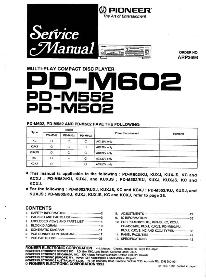
Popular CD Player manuals by other brands

Arcam CD23 Handbook

Arcam

Arcam CD23 Handbook

Sanyo MCD-Z1F Service manual

Sanyo

Sanyo MCD-Z1F Service manual

JVC RC-ST3SL instructions

JVC

JVC RC-ST3SL instructions

Technics SL-P9066 operating instructions

Technics

Technics SL-P9066 operating instructions

Marantz HD-CD1 quick start guide

Marantz

Marantz HD-CD1 quick start guide

Sony DVP-FX850 Service manual

Sony

Sony DVP-FX850 Service manual

Philips AZ1140 Instrukcja obs?ugi

Philips

Philips AZ1140 Instrukcja obs?ugi

Alpine 7909 owner's manual

Alpine

Alpine 7909 owner's manual

JVC CH-X350 instructions

JVC

JVC CH-X350 instructions

RCA RP-7923 instruction manual

RCA

RCA RP-7923 instruction manual

Philips Shockproof AX2102 brochure

Philips

Philips Shockproof AX2102 brochure

Philips CD582 user manual

Philips

Philips CD582 user manual

Philips AZ 6821 operating manual

Philips

Philips AZ 6821 operating manual

Lasonic MSU-2020 user manual

Lasonic

Lasonic MSU-2020 user manual

Denon DCD-1420 Service manual

Denon

Denon DCD-1420 Service manual

Panasonic SJ-MR100 operating instructions

Panasonic

Panasonic SJ-MR100 operating instructions

Onkyo DX-7210 instruction manual

Onkyo

Onkyo DX-7210 instruction manual

Cambridge Audio SONATA CD30 manual 

Cambridge Audio

Cambridge Audio SONATA CD30 manual 

manuals.online logo
manuals.online logoBrands
  • About & Mission
  • Contact us
  • Privacy Policy
  • Terms and Conditions

Copyright 2025 Manuals.Online. All Rights Reserved.

dV)
PIONEER’
The
Art
of
Entertainment
Service
Manual
COMPACT
DISC
PLAYER
PD-S605
PD-$505
PD-S505-G
THIS
MANUAL
IS
APPLICABLE
TO
THE
FOLLOWING
MODEL(S)
AND
TYPE(S).
AC220-
240V
ORDER
NO.
RRV1595
e
PD-
S605
AC110-
127V/220-
240V
With
the
voltage
selector
AC110-
120V/220-
240V
With
the
voltage
selector
CONTENTS
1.
SAFETY
INFORMATION
pene
cce
ee
eoeesereesesecessercees
2
5.
ADJUSTMENTS
eee
eee
eee
eee
rere
rere
eee
eee
ee
31
2.
EXPLODED
VIEWS,
PACKING
6.
IC
INFORMATION
-verssesereseeecree
teeter
ere
eeeees
36
AND
PARTS
LIST
-ercceereeerecreee
reese
3
7.
FL
INFORMATION
«+s
cceeccerceceeeccecceree
een
enes
37
3.
SCHEMATIC
AND
8.
BLOCK
DIAGRAM
cevcecececececcrececc
eer ete
ree
eees
38
PCB
CONNECTION
DIAGRAMS
-:---
11
9.
DISASSEMBLY/ASSEMBLY
-----------+--++---++°
39
4.
PCB
PARTS
LIST
---ecccccrececesteteceeeeessteeeeseeees
23
10.
PANEL
FACILITIES
«:++-+:-002sseccssesscecesecenaes
40
11.
SPECIFICATIONS
sea
eeeer
eee
cease
esenseenseseneces
41
PIONEER
ELECTRONIC
CORPORATION
4-1,
Meguro
1-Chome,
Meguro-ku,
Tokyo
153,
Japan
PIONEER
ELECTRONICS
SERVICE,
INC.
P.O.
Box
1760,
Long
Beach,
CA
90801-1760,
U.S.A.
PIONEER
ELECTRONIC
(EUROPE)
N.V.
Haven
1087,
Keetberglaan
1,
9120
Melsele,
Belgium
PIONEER
ELECTRONICS
ASIACENTRE
PTE.
LTD.
501
Orchard
Road,
#10-00
Lane
Crawford
Place,
Singapore
0923
©
PIONEER
ELECTRONIC
CORPORATION
1996
Fi
pret
oak
iat
ae
PD-
$605,
PD-
S505,
PD=
S505-G
1.
SAFETY
INFORMATION
r-
VARO!
AVATTAESSA
JA
SUOJALUKITUS
OHITETTAESSA
OLET
ALTTIINA
NAKYMATTOMALLE
LASERSATEILYLLE.
ALA
KATSO
SATEESEEN.
eanel
WARNING!
DEVICE
INCLUDES
LASER
DIODE
WHICH
EMITS
INVISIBLE
INFRARED
RADIATION
WHICH
IS
DANGEROUS
TO
EYES.
THERE
IS
A
WARNING
SIGN
ACCORDING
TO
PICTURE
LASER
1
INSIDE
THE
DEVICE
CLOSE
TO
THE
LASER
LASER
Kuva
1
DIODE.
Picture
1
Lasersateilyn
Warning
sign
for
r-
ADVERSEL
USYNLIG
LASERSTRALING
VED
ABNING
NAR
SIKKERHEDSAFBRYDERE
ER
UDE
AF
FUNKTION
UNDGA
UDSAETTELSE
FOR
STRALING.
varoitusmerkki
Jaser
radiation
IMPORTANT
THIS
PIONEER
APPARATUS
CONTAINS
LASER
OF
CLASS
1.
SERVICING
OPERATION
OF
THE
APPARATUS
SHOULO
BE
OONE
BY
A
SPECIALLY
INSTRUCTED
PERSON.
VARNING!
——
OSYNLIG
LASERSTRALNING
NAR
DENNA
DEL
AR
OPPNAD
OCH’
SPARREN
AR
URKOPPLAD.
BETRAKTA
EJ
STRALEN.
E
LASER
DIODE
CHARACTERISTICS
AXIMUM
OUTPUT
POWER:
5
mw
WAVELENGTH:
780-785
nm
LABEL
CHECK
INSERT
DISC
LABEL
SIDE
DOWN)
All
Types
WYXK,
WVXK,
WPW
and
RL
Types
Additionat
Laser
Caution
.
Laser
Interlock
Mechanism
The
position
of
the
switch
(S601)
for
detecting
loading
completion
is
detected
by
the
system
microprocessor,
and
the
design
prevents
laser
diode
oscillation
when
the
switch
(S601)
is
not
CLMP
terminal
side
(when
CLMP
signal
is
OFF,
that
is,
high
level).
Thus,
the
interlock
will
no
longer
function
if
the
switch
(S601)
is
deliberately
set
to
CLMP
terminai
side
(if
CLMP
signal
is
low
level).
In
the
test
mode
*,
the
interlock
mechanism
will
not
function.
Laser
diode
oscillation
will
continue,
if
pin
1
of
M51593FP
(
1C101
)
on
the
preamplifier
board
loaded
on
PICKUP
Assy
are
connected
to
GND,
or
pin
19
is
connected
to
low
level
(
ON
),
or
else
the
terminals
of
Q101
are
shorted
to
each
other
(
fault
condition
).
VARO!
Avattsessa
ja
suojalukitus
ohitetta-
essa
olet
alttiina
nakymattdnalle
lasersdteilylie.
Al&
Xatso
sadteeseen.
VARNING!
Osynlig
laserstraining
nar
denna
del
ac
Oppnad
och
sparren
ar
urkopplad,
Detraxta
e)
strdlen.
vewi2e7
a
CLASS
1
LASER
PRODUCT
VAW-328
WYXK,
WVXK,
WPW
and
RL
Types
WYXK
Type
CAUTION
INVISIBLE
LASER
__
ADVARSEL
USYWLIG
LASERSTRALING
VED
ABMING
MAR
SIKERHED
SAF.
GRYDERE
ER
UDE
AF
FUNKTION.
UNDGA
UDSATTELSE
FOR
STRALING
.
When
the
cover
is
opened
with
the
servo
mechanism
block
removed
to
be
turned
over,
close
viewing
of
the
objective
lens
with
the
naked
eye
will
cause
exposure
to
a
Class
1
laser
beam.
RADIATION
WHEN
OPEN,
AVOID
EXPOSURE
TO
BEAM
VORSICHT!
UNSICHTBARE
LASER-STRAMLUNG
TRITT
AUS.
WENN
OECEEL
{ODER
KLAPPE)
GEOFFIET
IST!
MICHT
DEM
STRAHL
ALSSE
TEN!
‘VR
1004
PRW1018
WVXK,
WPW
and
RL
Types
WYXK
Type
*
:
Refer
to
page
32.
PD-
S605,
PD-
S505,
PD-
S505-G
2.
EXPLODED
VIEWS,
PACKING
AND
PARTS
LIST
NOTES:
@
Parts
marked
by
“NSP.”
are
generally
unavailable
because
they
are
not
in
our
Master
Spare
Parts
List.
@
The
A
mark
found
on
some
component
parts
indicates
the
importance
of
the
safety
factor
of
the
part.
Therefore,
when
replacing,
be
sure
to
use
parts
of
identical
designation.
@
Parts
marked
by
“@
”
are
not
always
kept
in
stock.
Their
delivery
time
may
be
longer
than
usual
or
they
may
be
unavailable.
2.1
EXTERIOR
SECTION
(1)
CONTRAST
OF
PD
-
S605/WYXK,
PD
-
S505/WYXK,
WVXK,
WPW,
RD,
RL
AND
PD-
S505-
G/WYXK
PD-
S605/WY
XK,
PD
-
S505/WY
XK,
WVXK,
WPW,
RD,
RL
and
PD-
S505-
G/WYXK
have
the
same
construction
except
for
the
following:
Symbol
&
Description
PD-se0s
|
PD-ss5es
|
PD-s505
|
PD-ssos
|
PD-s505
|
PD-s505
|
PD-8505
IWYXK
IWYXK
IWVXK
wPW
{AD
AL
-
GIWYXK
COAXIAL
OUTPUT
PCB
Assy|
Not
used
Not
used
PWZ3256
Not
used
Not
used
Not
used
Not
used
Display
Window
PAM1612 PAM1612
PAM1612
PAM1597
PAM1597
PAM1597
PAM1612
Fuse
(T5A)
Not
used
Not
used
PEK1003
Not
used
Not
used
Not
used
Not
used
Tray
Name
Plate
PNW2658
PNW2658
PNW2658
PNW2658
PNW2658
PNW2658
PNW2665
Power
Button
PAC1712
PAC1712
PAC1712
PAC1712 PAC1712
PAC1712 PAC1779
26
Key
PAC1715
Not
used
Not
used
Not
used
Not
used
Not
used
Not
used
10
Key
Not
used
PAC1714
PAC1714
PAC1714
PAC1714 PAC1714 PAC1824
Function
Button
PAC1713
PAC1713
PAC1713
PAC1713
PAC1713
PAC1713
PAC1780
FUNCTION
PCB
Assy
PW2Z2871
PWZ2853
PWZ2853
PWZ2837 PWZ2837 PWZ2837
PW22853
PIONEER
Badge
PAM1608
PAM1608
PAM1608
PAM1704
PAM1704
PAM1704
RAN1011
Function
Panel
PNW2664
PNW2659
PNW2659
PNW2659 PNW2659
PNW2659 PNW2663
SWITCH
PCB
Assy
PWZ2874
PWZ3108
PWZ3108
PWZ2615
PWZ2615
PWZ2615
PWZ3108
Screw
ABA1192
ABA1192
ABA1192
Not
used
Not
used
Not
used
ABA1192
Screw
ABA1050
ABA1050
ABA1050
IBZ30P100FCC
|
IBZ30P100FCC
|
IBZ30P100FCC
ABA1050
Screw
ABA1011 ABA1011
ABAI011
BBZ30P060FCQ
BBZ30P060FCQ
ABA1011
AC
Power
Cord
PDG1003
PDG1003
PDG1055
RDG1022
PDG1013 PDG1003
PDG1003
Rear
Base
PNA2272 PNA2269
PNA2270
PNA2267
PNA2262 PNA2268
PNA2271
MAIN
PCB
Assy
PWZ3249
PWZ3243
PW2Z3244
PWZ3242
PWZ3241 PWZ3241
PWZ3243
SERVO
TRANS
PCB
Assy
PWZ2877
PWZ3111
PWZ3111
PWZ3113
PWZ3112 PWZ3112
PWZ3111
Screw
FBT40P080F2K|
FBT40PO080FZK|
FBT40P080FZK| FBT40P080FZK|
FBT40P080FZK|
FBT40P080F
2K
FBT40PO80FNI
Bonnet
PYY1162
PYY1162
PYY1162
PYY1162
PYY1162
PYY1162 PYY1177
Power
Transformer
PTT1236
PTT1236
PTT1236
PTT1236
Not
used
Not
used
PTT1236
(AC220
-
240V)
Power
Transformer
Not
used
Not
used
Not
used
Not
used
PTT1238
PTT1238
Not
used
(AC110-
127V/220
-
240V)
HEADPHONE
PCB
Assy
PWZ2618 PWZ3114
PWZ3114 PWZ3115
PWZ3115
PWZ3115
PWZ3114
Headphone
Knob
PAC1600
PAC1600 PAC1600
PAC1600
PAC1600
PAC1600 PAC1825
Screw
ABA1207
BBZ30P060FCQ
BBT3I0PO60FCCO
Loading
Mechanism
Assy
TT
PXA1582
PXA1581
PXA1581 PXA1581
PXA1581 PXA1581
PXA1581
Washer
WG40FCU
Not
used
Not
used
Not
used
Not
used
Not
used
Not
used
Earth
Plate
Not
used
Not
used
Not
used
Not
used
Not
used
Not
used
PBK1132
Screw
Not
used
Not
used
Not
used
Not
used
Not
used
Not
used
PPZ30P050FMq
Spacer
A
PEB1228
Not
used
Not
used
Not
used
Not
used
Not
used
Not
used
Caution
Label
(F)
VRW
-
328
VRW
-
328
VRW
-
328
VRW
-
328
Not
used
VRW
-
328
VRW
-
328
Caution
Label
(G)
VRW
-
329
VRW
-
329
VRW
-
329
VRW
-
329
Not
used
VRW
-
329
VRW
-
329
Caution
Label
VRW
1094
VRW1094
PRW1018
PRW1018
Not
used
PRW1018
VRW1094
Screw
Not
used
Not
used
ABA1101
Not
used
Not
used
Not
used
Not
used
Screw
Not
used
Not
used
IBZ30PO60FCC
|}
Not
used
Not
used
Not
used
Not
used
Caution
Label
HE
VRW1297
VRW1297
Not
used
Not
used
Not
used
Not
used
VRW1297
Screw
Not
used
Not
used
Not
used
IBZ30PO60FCC
|
IBZ30PO60FCC
|
IBZ30P060FCC
Not
used
Cord
Holder
Not
used
Not
used
ONF1128
Not
used
Not
used
Not
used
Not
used
PD-
S605,
PD-
S505,
PD-
S505-G
(2)
PARTS
LIST
FOR
PD-
S605/WYXK
Description
Mark
No.
l
2
3
4
5
6
7
8
NSP
9
10
1
12
NSP
13
14
15
16
17
A
18
A
19
NSP
20
A
21
NSP
22
NSP
=
23
NSP
24
25
Display
Window
Tray
Name
Plate
LED
Lens
Power
Button
26
Key
Function
Button
FUNCTION
PCB
Assy
Screw
PIONEER
Badge
Function
Panel
SWITCH
PCB
Assy
Screw
Insulator
Screw
Screw
AC
Power
Cord
Strain
Relief
Rear
Base
MAIN
PCB
Assy
SERVO
TRANS
PCB
Assy
PCB
Holder
Under
Base
Screw
Part
No.
PAMI1612
PNW
2658
PNW2019
PAC1712
PACI715
PACI713
PWZ2871
PPZ30P150FMC
PAM1608
PNW
2664
PWZ2874
ABA1192
PNW
1263
ABA1050
ABAIOI1
PDG1003
CM
-
22B
PNA2272
PWZ3249
PWZ2877
PNW2100
PNA2214
FBT40PO80FNI
Mark
No.
Description
Part
No.
26
Bonnet
PYY1162
A
27
~~‘
Power
Transformer
PTT
1236
(AC220-
240V)
NSP
28
HEADPHONE
PCB
Assy
PWZ2618
29
=
Screw
PDZ30PO050FMC
30
Stopper
PNM1070
31
Headphone
Knob
PAC1600
32
Screw
BSZ30P070FMC
33
Screw
ABA1207
NSP
34
Loading
Mechanism
PXA1582
Assy
TT
35
Washer
WG40FCU
36
Caution
Label
PRW1244
37
eeoeanee
38
eecene
39
eeecee
NSP
40
=
SpacerA
PEB1228
41
Screw
BBZ30P080FCC
42
Getter
PRW1455
NSP
43
Caution
Label
(F)
VRW
-
328
44
Caution
Label
(G)
VRW
-
329
45
Caution
Label
VRW1094
46
eeonvee
47
oe
eee
NSP
48
Caution
Label
HE
VRW
1297
49
oeeee
50
eececee
PD-
S605,
PD-
S505,
PD-
S505-G
“35
iPD-
S605
‘Only
14(WYXK,
WVXK)
25
1
Se
bye
-
41(WPW.
RD,
RL)
NOTE.
Screws
adjacent
to
W
mark
on
the
product
a
me
y
“
PPS:
i.
ae
PD~S505/
are
used
for
disassembly.
Pee
paler
ge
Except
WPW.
RD
and
RL
Only
De
<a
:
a
a
PD-$505/RD
30
oer
|
‘ic
!
1
i 1 i
i]
'
( 1
bs
wel
ToS
Sas
Refer
to
Ae
“2.2
LOADING
MECHANISM
ASSY
TT”.
34
18—|
!
zy
\
1
1
PD-S505/WVXK
Only
r
1
Fuse
Holder
IWXK
Only
Except
|
PD-S505/RD
Al
ee
=
ee
50
|
oa
}
18
'
{
\ i
WYXK
and
WVXK
Only
ZZ
+
41
PD-
$505
PD-
$505
and
PD-
$505-G
Only
H
L
ae
F?
:
>
.
;
|
IWVXK
Only
PD-$505-G
Only
ws
|
APY
ee
a.
oe
(14
i
WYXK
and
2
;
Sc
PD-$505
™
WVXK
Only
|_~
oN
RR
ne
WYXK
Only
Note
‘
The
stopper
consist
of
the
big
ring
part
and
the
small
ring
part
If
you
stick
the
stopper
to
the
leg,
stick
the
big
ring
part
to
the
front
leg,
and
the
smail
ring
part
to
the
rear
leg.
{For
the
(For
the
front
leg)
Tear
leg)
PD-
S605,
PD-
S505,
PD-
S505-G
(PXA1581
:
PD-
S505,
PD-
S505-
G)
2.2
LOADING
MECHANISM
ASSY
TT
(PXA1582
:
PD-
S605)
PD-
S605,
PD~
S505,
PD-
S505-G
2.3
PACKING
Parts
List
(1)
CONTRAST
OF
PD-
S605/WYXK,
PD
-
S505/WYXK,
WVXK,
WPW,
RD,
RL
AND
PD-
S505-
G/WYXK
Mark
No.
Description
Part
No.
Mark
No.
Description
Part
No.
PD-
S605/WY
XK,
PD-
S505/WY
XK,
WVXK,
WPW,
RD,
RL
and
PD-
S505-
G/WY
XK
have
the
same
construction
except
for
the
following:
1
Lever
Switch
(S601)
DSK1003
48
PWB
Holder
PNW2057
2
Float
Screw
PBALO27
NSP
49
Earth
Lead
Unit
XDF-503
=
3.
Rubber
Belt
PEB1186
50
MECHANISM
PCB
Assy
PWX1192
Symbol
&
Description
Remarks
4
Motor
Pulley
PNW1634
51
Cord
Clamper
PEC
-
107
IWYXK
WYXK
IWVXK
/WPW
/RD
/AL
-
GIWYXK
5
Drive
Gear
PNW1996
NSP
52
Servo
Mechanism
Assy
PXAIS83
Operating
Instructions
PRE1232
|
PRE1232
|
Notused
|
Notused
|
Notused
|
Notused
|
PRE1232
(English/French/German/
6
Synchro.
Lever
PNW2168
53.
Screw
BPZ26PO060FMC
Italan/Dutch/Swedish/
7
Gear
Pulley
PNW
1998
54
Tum
Table
Assy
PEA1165
Spanish/Portuguese)
8
SW
Head
PNW1999
(PD-
S60S)
Operating
Instructions
Not
used
|
Notused
|
PRB1239
|
Notused
|
Notused
|
Notused
|
Not
used
9
Float
Base
PNW2000
54
Tum
Table
Assy
PEA1199
(English)
10.
Left
Cam
PNW
2001
(PD-
S505
and
PD-
S505
-
G)
Operating
Instructions
Not
used
|
Notused
|
Notused
|
PRE1231
|
PRE1231
|
PRE1231
|
Not
used
11
=
Right
Cam
PNW
2002
NSP
55
_
Table
Base
Assy
PXA1382
(English/Spantsh/Chinese)
12
Compression
Spring
PBH1120
56
Shaft
Holder
PNB1382
Remote
Control
Unit
PWW1060
|
PWW1061
|
PWW1061
|
PWW1061
|
PWW1061
|
PWW1061
|
PWW1095
13.
Tension
Spring
PBH1121
Battery
Lid
PZN1001
|
PZN1010
|
PZN1010
|
PZN1010
|
PZN1010
;
PZN1010
|
PZN1013
14.
Float
Rubber
PEBIO14
Protector
R
PHA1261
|
PHA1261
|
PHA1257
|
PHA1238
|
PHA1238
|
PHA1238
|
PHA1261
15
Table
Rubber
Sheet
PEBI181
CD
Packing
Case
PHG2181
|
PHG2172
|
PHG2173
|
PHG2169
|
PHG2169
|
PHG2169
|
PHG2174
16
Tray
PNW2003
«
How
to
install
the
disc
table
Spacer
Not
used
|
Notused
|
PHC1078
|
Notused
|
Notused
|
Notused
|
Not
used
17.
Table
Guide
PNW2004
‘
:
Vinyl.
Bag
Notused
|
Notused
|
221-013
|
Notused
|
Notused
|
Notused
|
Not
used
18
Lock
Plate
PNW2005
Useinippers
.
:
elie
COLO
CUL
ATE
SO
Se
CLONS
Cord
with
Miniplug
Not
used
|
Notused
|
Notused
|
PDE1247
|
Notused
|
Notused
|
Not
used
marked
(A)
in
figure
Then
remove
the
spacer
19
D.C.
motor
PXMIOQIO
,
:
.
Warranty
Card
ARY7010
|
ARY7010
|
ARY7010
|
PRY1002
|
Notused
|
Notused
|
ARY7010
(0.75W,
LOADING)
While
supporting
the
spindle
motor
shaft
with
20
Rubber
Bush
sae
the
stopper,
put
the
spacer
on
top
of
the
carriage
base
21
Rubber
Bush
PEB1I17
:
F
o
Fo
Screw
BMZ26PO40FMC
Sse
the
disc
table
on
top
(takes
about
9Kg
(2)
PARTS
LIST
FOR
PD-
S605/WYXK
23.
Screw
IPZ26PO60FCU
3
;
p
:
24
Screw
IPZ20PO80FMC
Take
off
the
spacer.
Mark
No.
Description
PartNo.
__
Fe
Acs
1
Cord
with
Pin
Plug
PDE1248
a
2
2
Operating
Instructions
PRE1232
26
ae
B
Leen
5
(English/French/German/Italian/
27
heey
shales
Dutch/Swedish/Spanish/Portuguese)
:
NSP
28
~~
Table
Bearing
Assy
PXA1383
(pressure
of
about
9Kg)
&:°
PemoteContial
Linit
PWW1060
Ld
SSUSWVAK
Only
NSP
29
Turn
Table
(AL)(PD~
S605)
PNRI035
F
disc
table
"
Rear
View
6
,
i]
4
Battery
Lid
PZN1001
,
'
NSP
29
=
Tum
Table
(AL)
PNR1044
'
'
Except
(PD--
$505
and
PD-
S50S-
G)
oe
Seieeet
PD=
S505).
FD
“SS0e/AP
and'Bt
30
D.C.
Motor(CARRIAGE)
|
PXM1027
7
Ci
Packing
Casé
PHG2181
A
ony
13;
31
Pinion
Gear
PNW2055
Spacer
seting
m
Niscoe
Mar
Sheet
793.007
ae
ee
ee
32
D.C.
Motor
Assy
PEA1
236
ee
;
;
'
ff
;
!
. .
motor
1
Ree
aS
eo
Sie
2
(SPINDLE)(with
oil)
as
NSP
9
Dry
Cell
Battery(RO3,
AAA)
VEM-
022
™
11
:
q
2
33
Carriage
Base
PNW2445
7
aay
peel
34
Disc
Table
PNW
1067
i.
wees
ase
35
Screw
JFZ20P030FNI
36:
Berew
FZ17PO25FZK
NSP
13.
Warranty
Card
ARY7010
37
=
Gear
3
PNW2054
38
Gear
2
PNW2053
39
Washer
WT12D032D025
40
PICKUP
Assy
PEA1291
41
Guide
Bar
PLA1094
PD-
S505/WVXK
Onl
42
Gear
|
PNW
2052
NSP
43
—
Gear
Stopper
PNB1
303
44
Screw
BPZ20PO060FMC
45
Spring
PBH1132
NSP
46
Mechanism
Base
TT
PNB1431
47
=
Screw
BPZ26P
1
00FMC
PD-
S605,
PD-
S505,
PD
-
S505-G
1.2Vp-p
LOADING
MECHANISM
ASSY
TT
TP1-
Pin6é:
1C202-
Pin
4:
PLAY
MODE
Upper:
TP
1-Pin1(RF)
Neng
582
:
PD-
S605)
eee
te
gieetnategeeeo
ios
se
:
:
aes
3.
SCHEMATIC
AND
PCB
CONNECTION
DIAGRAMS
|
ees
I
|
PAs
gs
ny
ay
ee
ee
eS
<
Seg
a
5
=
a
a
ee
za
rane
2
s
Eo
a
ae
oe
ee
eR
i
leege
Pag
Fa
ee
peel
4
|
| |
PICKUP
ASSY
|
raw
|
[i
(||
---——(PEA1291)
_
OR
if
|
WAVEFORMS
|
|
|
|
HOLOGRAM
LASER
UNIT
Ras
\}
|
*]
SOT-JUMP
:
After
switching
to
the
pause
mode,
|
|
srecchaner
con”
reeue
col
A
b,
|
|
+
ely
Note
:
The
encircled
numbers
denote
measuring
points
in
the
press
the
manual
search
key.
1]
|
F
roore.s
iy
CN102
£
schematic
diagram.
*2
FOCUS-IN
:
Press
the
key
without
loading
a
disc.
|
|
or
2
=
ret
TP4-
Pin
1:
IC202-
Pin
3:
(@)
16202:
Pin
9
Gg)
!6301-
Pin
21
:
i
|
|
ants)
y
PLAY
MODE
PLAY
MODE
TRACK
SEARCH
PLAY
MODE
(1kHz)
fit
ier
[we
2a
|?
My
(RF)
(FODR)
MODE
(CADR)
(DATA)
|
|
|
M5
1593FP
x
H
:
500nsec/div
H
:
1msec/div
H
:
500msec/div
H
:
500usecidiv
|
|
il
2
CORK
6)
WR
fa
I
is
B
1
|
|
1
—
li
4
io
|
Gr,
TP1-
Pin
1:
IC202-
Pin
4:
1G151-
Pin
32
:
TRACK
SEARCH
MODE
i
||
|!
TRACK
SEARCH
PLAY
MODE
PLAY
MODE
Upper:TP1-Pin1(RF)
Jue
'
|
MODE
(RF)
(TRDR)
(EFM)
Lower:IC151-Pin
29
|
|
|
||
i
H
:
200usec/div
H:
msec/div
H
:
500nsec/div
piiaiseciay
ioe
!
|
i
1
7
Ss
|
|
i
|
|
|
|
|
z
(10)
Latta
Ae
PLAY
MODE
50T-JUMP(#1)
MOD
PLAY
MODE
(1kHz
:
PD-
ees
(FOER)
(TRDR)
(C0)(D/A
DATA
oun
Lower:C151-Pin
30
PXAI581
:
PD-S505,
PD-
S505-
G)
cameo
:
,
.
‘
H:
200psec/div
*
(DFCT)
ic
ana
I
a
ee
ee
PXM1027
+
t
i
Bak
pee,
SYP]
1:
200usecidiv
1.5Vp-p
F:
|
TP1-
Pin2:
1C201-
Pin
1:
1C401-
Pin
10:
1C301-
Pin
3:
a
et
5
|
PLAY
MODE
PLAY
MODE
PLAY
MODE
ets
PLAY
MODE
SWITCH
cB
ASSY
‘
(TRER)
(SPOR)
(LO)(D/A
DATA
OUT)
(MDP)
PWZ2874
;
PD-S805/WYXK)
‘
PWZ3108
:
PD-
S505/
WYXK.
WVXK,
|
-
H
:
10msec/div
H
:
50msec/div
H:
200psec/div
H
:
2usec/div
a
fea
LOADING
MOTOR
|
|
|
PD-S505-
|
(PWZ2615
:
PD-
S505/WPW,
RD,
RL) |
|
|
|
STAND
BY
LED)
0751
{
PCX1019
|
TP1-
Pin
2:
1C201-
Pin
1:
(16)
1C301-
Pin
22:
WCS01s.
PINS
EE
aT
Ne
en
ge
ht
ey
See
a
ey
ene
BOT
JUMP(+1)MODE
TRACK
SEARCH
PLAY
MODE
(1kHz)
PLAY
MODE
FUNCTION
PCB
ASSY
(Pwz2871
:
:
BD-
SB05/WYXK)
|
(TRER)
MODE
(SPDR)
(BCLK)
(PCO)
ieee
‘B-
$508-6))
H:
Imsec/div
H
:
50msec/div
H:
500nsec/div
H:
10psec/div
|
5Vp-p
AWWA
AAAAAAAKUAKAAKAAKAAAAL
FCCLA
CLEA
CC
3.5Vp-p 6.2Vp-p
v701
PEL1085
FLUORESCENT
DISPLAY
5Vp-p
$0X17685-51
REMO
re
1C202-
Pin
3:
FOCUS-IN(#2)
MODE
(FODR)
(8)
IC202-
Pin
9:
PLAY
MODE
(CADR)
H
:
2sec/div
(18)
1C301-
Pin
20:
PLAY
MODE
(1kHz)
(LRCK)
H:
10usec/div
H
:
200msec/div
1.8Vp-p
14
PD-
S605,
PD-
S505,
PD-
S505-G
ar
RKP_S33
.
ves
VO]
wx
P0452,
0456:
MUTING
DRIVERS”
ee
Te
ae
OR
A
wnat
Ord
1
5
®
PWz32
ONLY,
Vtz21
caaz,
Yt
OMY
|
1C421,
Q421
:
vireo)
\_*
a4
(
:
K
;
321
i
Jas01
|
‘OPTICAL
~~
|
REGULATOR
Green
1C405
(1/2,
2/2)
:
eeyasonee
Oe
0
“Siwy
(TOTX178
Spl
ict
hal
he
+5DA
LOW
PASS
FILTER
BD.
9806
/
WYK
6)
IS
:
PD-
S505
O452
ONLY
_
a
==
v+8
Cpveey
2
jos
t
DTA124E
(P)pas2
*
Jj
Al
N
2SC3066
H
NA
47Ko
Rass
€
C452
'
c
aN
O
O
:
47
|
47/50
ss
|
y
'
Us
iait,
26
2e
so
4
0453,
0454
:
|
an,
a)
WYXK,
WVXK!
P20
|
C423
a
Care
SP.
a0
Jea
|
2
1)
enn
Lo
ONLY
u
ca22d
cart
WY
10
uO
wae
kth)
ee
gee
226/35,
__|
Sich
ity
eats
MUTING
| |
=
@yma:
ape
ool
bean
ease”
‘ONY
tra
T00K
(25K24—p
100/50
Sar
iitees
Wise]
as
|
—
t
1
‘
a)
ee
1s
:
ee
aes
re
a
a
PNB
oT
ee
|
oe
! !
lo)
v4
oe
eis
oa
ee
eS
WYXK.
WWXK
8
a
~
Aue
(0)
vasora72)
|
eesigllee
Re
ey
)
a
|
VA
R368
neal
1
AR
a
C407
100750
WYXK,
WVXK]
OnLy
raze
Ae
a
RA5E
ry
PKB1009"
wow.
RE
PCB
ASSY
(PWZ3256
4
oN
Yvc
10K
470/50
WPW.
RD,
RL
Bed
62K
R44
=
D
'
OTHERS
aK
nage
8
DKB1013.
WYXK,
WVXK
¢
V+S,
Ngee
C432
28103
‘
FI)
¥
X401_PSS1008
Tht
=
EIS
(
forR.
ss
xe
(18.9344MH2)
ci
\
t]
Rese
S
oD
Ea
220/25
1
|
|
RAS
P
Ala
|
CINEOUT
uack
SIGNAL
ROUTE
gp
ptren
oh
9
404
aoe
OO!”
aa
cence
wrxk,
wxK
!
|)
22!
CS)
Dy
|
vx
K
cH
22P
ONLY
‘bis
ass4
3
@®
:
AUDIO
SIGNAL
ROUTE
ON
3
3
9
x40l
v8
av
):
SPINDLE
DRIVE
ROUTE
Oj
Bg
t
Garth
won,
wxe
es
X
“2:
FOCUS SERVO
LOOP
LINE
ee
Ly
c
=
TT
|
85
i
1
OK
2
“2a:
TRACKING
SERVO
LOOP
LINE
Rta
In
Pow
Rs
|_|
R430
22K
its
7a)
°
©:
CARRIAGE
SERVO
LOOP
LINE
!
;
5
wk:
LOADING
MOTOR
ROUTE
>
7
‘i
aed aio
5
|
@
[Hi-—bit
IC]
ae
Seer
vasa
Rees
Ts
aa
CO}
$812
/
aw
oo
bg
RBIDLaIe
IL415'WYXK,
WVXK
560
470
DKB1013:
WYXK,
WVXK
11
‘
L301
Rasioaes
2200
5“)
LLaH
ONLY
|
Ne
C2198
8782
Bont
(wexk,
WXK
P
R451
1
RATS
loo
0.00
alll
ia
pip
RAad,
47K
R453
47/50
0453
Rao?
x
|
'
eet,
ype
et
eas
pe
Bs
a
jo
teenth
—
i
ae
os
eee
loe
D218
SP
v+8
8,
|
{
:
PD-
YXK,
Pe
C401
:
D/A
CONVERTER
i)
ab
ag
ves)
|
SPINS
TA
OO
te
KR
[AL
INSD
7)
216
ass
om
FA
1c406
-
<
n
PD-$505-
G/WYXK)
{
O}
ow
4p
re
(i)
ere
Sats)
aoe
Nw
&|
.
&
|
(PWZ3115
:
PD-S505/WPW,
RD,
RL)
|
rhewe
Le,
TE
ae
ye
WHC
7Gaps
poe
ee
eS
ee
acid
|
SE
|
[ueaperone
—SESISTORS.
(unit
a)
(2
47
bad
i
zi
oe
ICAOR
3
A
ONLY
0.001
ae)
9322
dy
DTA124ES
0716:
os
*
ate
1
WAR
WVXK,
aaca
Fd
i)
&
wreot
HEADPHONE
Unmarked
Type
1/4W
Type
lo)
R219
(SPINDLE
DRIVE)
Uy
orc
1
24
oe
“Tresv
NYMA558DX
—-
POSSO5/
WPW.
RD,
RL
a
8
See
1ez01
472)
xRST
a
bat\
Q)
Or
CabaT
aH
AT
|
CAPACITORS
(UNIT
mF)
‘
|
vesM
1406
(1/2,
2/2)
:
*
Fe
2
I
ent
002
oho
aR
nny
a
Le
|
R244
HEADPHONE
AMP,
O}—
Oy,
|
ee
ee
ecb
te
if
rou
ote)
Sey
0405,
0451,
0455
meal
“ar
|
‘i
ees
(4)
YX
Coramie
CRCYX
e
;
Risa
VRI
,
:
:
Or
amie
IS®
ON,
eso
LOT
Ae
meen
"Es
|
Bg
MUTING
DRIVER
=
Y-®
ee
e406
(272)
|
SSL
Ceramic
CCCSL
Qn
ie
F)
fee
$
Unmarked
type
CKCYF
Ise
F
2&
was
Le
INVERTER
BUFFER
=
asa
A
| |
ono
(WVUnmarked
Electrolysis
CEAS
ot
205
02v
h
ibe
Ecae
28617408
ae
L
(8)
TX
Fiim
CFTXA
oe
a
YB
R395
a,
SSS
SSS
SSS
(9)
PU
Ceramic
CKPUYF
Gye
R205
R242
‘Ww
ror
ge
ed
EES)
oon
23K
syncs)
(10)
ZA
Starget
CEZA
am
r
cee
ale
q
*
5
[a
|
DECK
SyNCHRO.
ACK
Gajaa
siimre
ceGA
fam
|yhuca
|
van
Sp0025
FOIN
Rsos
a
|
Ja3s93
(12)
PA
Polypropylene
CQPA
i
-
WYXK,
WVXK
HHS
SSeS
ates
240K
ma
Yer
|
PKN1
005
Or
Al
>
Belk
:
45.
|
SYNC1
Saraedl
babe
|
INDUCTORS
>
6)
‘
&
oo
'
H
R394
p397]
D395
|
@
SERVO
TRANS
PCB
_ASSY
(1)
Unmarked
type
LAU
a)
(TRACKING
DRIVE)
R234
D393
1K
16202
(273)_22K
|
1.7
c216
rsaig
fisszss
A
|
ASS2547:9.5525¢
|
PO
S805
|
PD.
S805/
(2)Radial
type
LFA
RORA,
LAeS20
1
240K
0392,
C391
fe
if
SS
S|
JWYXI
|
IWYXK,
W¥XIKTWPW,
RD.
RL
¢
YX
0047
THER
}
eo
©
sty)
WTTZ
4
JA392—
guy
|
ue
e
OTHERS
ov
:
i
K
ps04
RKN1
004
PL
*
GND
caio
ee
“4!
1
0384)
:
C15,C16
ef
R210
Wine
wae
HX2
]
C
3
51
I]
be
'
|
|
SR
JACK
|
CIT7.C18
CHASSIS
ee
47
;
vss
i
g
4
|
:
PCHI1I9
ABC
LOW
ACTIVE
SIGNAL
336
PD4702A
o]
0391
A
v392
JASS1
iN
PCHINI9
t
er
a.
|
RKN1
004
|
(CARRIAGE
DRIVE)
(SYSTEM
CONTROL)
'
|
‘
16202
(323)
A
C333
Sees
gee
ft
|
A
(tAG5208)
‘xea
|
so]
of
le
me
PD-$505
cee
hel
WYXK,
WVXK,
WW
=
PW
,
,
|
|
oN
ts
cn
as
Spe
ney
canner
MODEL,
PO.
SEOR
WOER,
WX,
Pinal
ng
eee
Sar
oo
sani
|
J
OMe
To
Foros
Nie
MPD
BY
RoW
AC220-240V
AC110-127V/220-240V
PR
See
ORES
ex
f =
gaat
S0760H2
=
AppG1015
RD
i:
RO,
keEnnEneninen
°
|
LSGaaiaad
~-—-———————~—~—~-—,
|
ac
POWER
CORD
be
Pe
ge
Se
;
ental
a4
1€
PROTECTOR
A
011-014
ss6e8c
ebasGas-
wink
Aposi003
RL
BA,
WYK
|
Aiczo
{ics
yy
=
fpTHi0is3
|
Seeman
AC
POWER
CORD
care)
:
A
A
as
POG1OSS
WxK
eats
(272)
ONLY
Ps
need
en
GC
er
a
Gr
O
|
SS:
VOLTAGE
APSB1006
cassty.
|
BR
a
56
|
SELECTOR
|
C27
3]
PaosrRi2
|
c2s
|
013
Shaye
ees
f |
=
—
Ajc19
0
01
!
L
WYXK,
WVXK
ONLY
C26
|
Fi
|
ACI
ACZ
CN352
52147-1510
1C20:
SYSTEM
RESET
&
|
d
Id
+
5V
REGULATOR
|
CN351
3
a
:
|
p—-——
——
—
~
—
--
PUL
OOOO
O08
O08
000006680
IO@O@E
!
>
IOOS
oF
MOO
OOOOOOOQOQDO000O
SS
SS
eS
a
Se
ee
ee
wee
7
R54
$r524R53
ee
|
|
TeSKST
Se
TSK
OSA
TRANSFORMER
|
lent
J701
D20PWY1715E
A
PTT:238
RD.
RL
J702
D20PWY1520E
aes
we
4
ZWNN1007G20—0-~32F
BOOS
ATT
ONS.
SNT0
|
:
PD-
PWZ3112
:
PO-
S505/RD,
RL
pws
:
PD-
SS05/WYXK,
WVXK,
PD-
S505-
G/
WYXK)
{owes
13
:
PD-
SS05/
WPW)
d
UV
15
PD-
S605,
PD-
S505,
PD-
S505-G
NOTE
FOR
SCHEMATIC
DIAGRAM
(Type
4A)
.
When
ordering
service
parts,
be
sure
to
refer
to
“PARTS
LIST
of
EXPLODED
VIEWS”
or
“PCB
PARTS
LIST”.
-_
.
Since these
are
basic
circults,
some
parts
of
them
or
the
values
of
some
components
may
be
changed
for
improve-
ment.
RESISTORS:
Unit:
&kQ,
M:MQ,
or
Q
unless
otherwise
noted.
Rated
power:
1/4W, 1/6W,
1/8W,
1/10W
unless
otherwise
noted.
Tolerance:(F):
+
1%,
(G):+2%,
(K):+
10%,
(M):
+
20%
or
+5%
unless
otherwise
noted.
>
.
CAPACITORS:
Unit
:
p:pF
or
4.
F
unless
otherwise
noted.
Ratings
:
capacitor
(\
F)
/
voltage
(V)
unless
otherwise
noted.
Rated
voltage
:
50V
except
for
electrolytic
capacitors.
5.
COILS:
Unit
:
m:mH
or
,.H
unless
otherwise
noted.
6.
VOLTAGE
AND
CURRENT:
LI
or
+Vv:
DC
voltage
(V)
in
PLAY
mode
unless
otherwise
noted.
mA
or
—mA:
DC
current
in
PLAY
mode
unless
otherwise
noted.
Value
in({
—)
is
DC
current
in
STOP
mode.
7.
OTHERS:
e@or@
=:
Adjusting
point.
od
:
Measurement
point.
@
The
A
mark
found
on
some
component
parts
indicates
the Im-
portance
of
the
safety
factor
of
the
parts.
Therefore,
when
replacing,
be
sure
to
use
parts
of
identical
designation.
8.
SCH
-
()
ON
THE
SCHEMATIC
DIAGRAM:
@
SCH-
Dindicates
the
drawing
number
of
the
schematic
diagram.
(SCH
stands
for
schematic
diagram.)
9.
SWITCHES
(Underline
indicates
switch
position);
MECHANISM
PCB
ASSY
$610:
INSIDE
OUT
OF
PCB
ASSY
S601
:
CLAMP
FUNCTION
PCB
ASSY
SWITCH
PCB
ASSY
$701:
&
OPEN/CLOSE
$751:
RANDOM
$702:
8
$752
:
HI-LITE
SCAN
$703:
I
$753
:
POWER
STANDBY/ON
S704:
>
$754:
DISPLAY
OFF
$706
:
REPEAT
$708
:
TIME
$709
:
PGM
$712:
CLEAR
$713;
EDIT
S714;
S715;
S716:
S717:
S718:
$719:
$720:
$721
$722
$723:
S724:
Kd
<4
S725:
b>
PPI
$726
:
>
10
(PD-S505,
PD-S505-G
Only)
$728
;
15
(PD-S605
Only)
$729
:
20
(PD-S605
Only)
$730:
>
20
(PD-S605
Only)
$731:
11
(PD-S605
Only)
$732
;
12
(PD-S605
Only)
$733
;
13
(PD-S605
Only)
$734
;
14
(PD-S605
Only)
$735
;
16
(PD-S605
Only)
$736
:
17
(PD-S605
Only)
$737
:
18
(PD-S605
Only)
$738
:
19
(PD-S605
Only)
Senrneasean-s?
NOTE
FOR
PCB
DIAGRAMS:
1.
Part
numbers
in
PCB
diagrams
match
those
in
the
schematic
diagrams.
2.
A
comparison
between
the
main
parts
of
PCB
and
schematic
diagrams
is
shown
below.
Symbol
in
PCB
Symbol
in
Schematic
BCEBCE
Transistor
BCE
B
Transistor
with
resistor
C
EBCE
DGSO6GS
ria
HH)
|
3-terminal
regulator
Field
effect
transistor
e
PCB
DIAGRAM
OF
MECHANISM
PCB
ASSY
MECHANISM
PCB
ASSY
40
@
This
diagram
is
viewed
from
the
mounted
parts
side.
e
PCB
DIAGRAM
OF
MOTHER
PCB
ASSY
(a
es
a
ee
~
ee
ee
ae
eee
ORE
eer
ee
eee:
-
CON
Omen
Seen
Seer
eee
Pe
ee,
Sa
oer
COAXIAL
OUTPUT
PCB
ASSY
lo.
X
Y
PartNo.
SEMICONDU
SERVO_TRANS
10331
35
19
MCT4HCUD4N
ut
MAIN
PCB
ASSY
'
MAIN
PCB
ASSY
_No.
X
Y
PartNo.
_
SEMICONDUCTORS
ci
"6
6
CXA13720
1201
74
74
LAGSI7
MECHANISM
1202
127
76
LA6520
Teenie
tere
ro
1301
74
107
CXD2507AQ
1341
108
132
PD0236AD
1351
31
75
PD4702A
a
ee
| .
Yyy.
AAL
ae
2S
een
>
mT
1401
146
135
PD2029A(L)
»
OoPe
Yj
=
:
;
a
Was.
2:
1C405
183 120
M523BAP
:
B
hiese
;
1C406
228
122
M5218AP
10421
161
94
NJM2930L05
0322
130
141
DTC124ES
0323
65
121
DTC124ES
0391
12577
2SC1740S
0403
206
135
2S02144S
0404
207
105
2s02144S
0405
167 134
DTCI24ES
0421
175
98
2SC3068
0431
177
109
2SK246
0432
183
109
2SJ103
0433
180
133
2SK246
0434
186
132
2SJ103
0451
152
134
DTAI24ES
0452
167
104
DTAI24ES
0453
140
206
2SD2144S
0454
207
100
2S02144S
0455
161
133
DTC124eS
0456
176
104
OTC124ES
D351
18
53
188254
D352.
«18
48
=
MTZJ5.
1B
D395
216
68
1$S254
D396
«216
60
1$S254
D397
216
70
+
1$S254
D451
189 134
188254
sg
hd
D452
193
106
1$S254
HE
ADPHON
D453
195
134
1$S254
J501
D454
198
100
1SS254
D496
198
111
56886
(PNPI411-B
)
@
PCB
LOCATION
COAXIAL
OUTPUT
PCB
ASSY
@St
@
“Side”
is
indicated
the
mounted
parts
side
of
the
PCB
diagram.
e
“X"
and
"Y"
are
indicated
the
mounted
parts
coordinate
of
the
PCB
diagram.
@
When
referring
to
the
parts
position,
be
sure
to
check
with
the
PCB
PARTS
LIST.
@
This
diagram
is
viewed
from
the
mounted
parts
side.
@
The
parts
mounted
on
this
PCB
include
all
necessary
parts
for
several
destinations.
For
further
information
for
respective
destinations,
be
sure
to
check
with
the
schematic
diagram.
MAIN
PCB
ASSY