Pioneer 500 ST User manual


Part No. 4801-5154 Rev 4-08 Table of Contents 500 ST Door
Table of Contents
1. Ratings and Specifications...........................................................................................................................3
2. Warnings (Avertissements)..........................................................................................................................4
3. Limited Warranty.........................................................................................................................................8
4. Physical Description/Drawing .....................................................................................................................9
5. Use of Equipment ........................................................................................................................................9
6. Installation ...................................................................................................................................................9
6.1 Tools Required......................................................................................................................................9
6.2 Overview ..............................................................................................................................................9
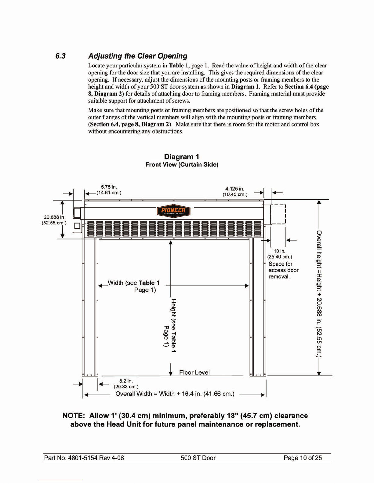
6.3 Adjusting the Clear Opening .............................................................................................................10
6.4 Attachment Points of Door................................................................................................................11
6.5 Assembly of Parts...............................................................................................................................12
6.6 Infrared Sensor Connectors ................................................................................................................13
6.7 Fastening Door Assembly to Clear Opening......................................................................................13
6.8 Connecting the Electrical Power.........................................................................................................15
7. Operation of Door......................................................................................................................................15
8. Limit Switches...........................................................................................................................................15
9. Manual Operation of Door.........................................................................................................................16
9.1 Operating Instructions ........................................................................................................................16
9.2 Adjustment of Brake...........................................................................................................................17
10. Emergency Egress......................................................................................................................................18
11. Door Panel Adjustments............................................................................................................................20
12. 500 ST Door Wiring Diagram ...................................................................................................................21
13. Pioneer Smart Controller Wiring Diagram................................................................................................22
Please Retain This Manual for Future Reference


Part No. 4801-5154 Rev 4-08 500 ST Door Page 4 of 25
2. Warnings (Avertissements)
Warning!
Disconnect All Power Sources Before Installing This Equipment. Failure To Disconnect Power
Source Can Result In Property Damage, Serious Injury Or Death!
Warning!
Dangerous Rotating Machinery!
Keep Hands, Clothing, Etc. Clear When Operating!
Do Not Operate Without All Guards And Covers In Place!
Warning!
All Wiring Should Be In Accordance with National Electrical Codes Or Other Local Codes.
Warning!
The Installer Is Responsible For Complying With All Relevant Regulations, Such As National
Wiring Regulations And Accident Prevention Regulations. Particular Attention Must Be Given
To The Cross-sectional Areas Of Conductors, The Selection Of Fuses Or Other Protection, And
Protective Earth/Ground Connections!
Warning!
The Voltages In The Power Cables And Certain Parts Of The Drive Can Result In Death.
Whenever The Drive Has Been Used It Must Be Isolated And Disconnected For 5 Minutes
Before Any Work Commences.
Danger!
Only Qualified Electrical Personnel Familiar With The Construction And Operation Of This
Equipment And The Hazards Involved Should Install, Adjust, And/Or Service This Equipment.
Read And Understand This Manual In Its Entirety Before Proceeding. Failure To Observe This
Precaution Could Result In Severe Bodily Injury Or Death!
!
!
!
!
!
!
!
!
!
!

Part No. 4801-5154 Rev 4-08 500 ST Door Page 5 of 25
IMPORTANT INSTALLATION INSTRUCTIONS
WARNING!
To reduce the risk of severe injury or death:
1. READ AND FOLLOW ALL INSTALLATION INSTRUCTIONS.
2. Do not connect the door operator to the source of power until instructed to
do so.
3. Locate the control station: (a) within sight of the door, (b) at a minimum
height of 5 feet so small children cannot reach it, and (c) away from all
moving parts of the door.
4. For products having a manual release, instruct the end user on the
operation of the manual release.
IMPORTANT SAFETY INSTRUCTIONS
WARNING!
To reduce the risk of severe injury or death:
1. READ AND FOLLOW ALL INSTRUCTIONS!
2. Never let children operate or play with door controls. Keep the remote
control (where provided) away from children.
3. Personnel should keep away a door in motion and keep the moving door
in sight until it is completely closed or opened. NO ONE SHOULD
CROSS THE PATH OF A MOVING DOOR.
4. Test the door’s safety features at least once a month. After adjusting
either the speed or the limit of travel, retest the door operator’s safety
features. Failure to adjust the operator properly may cause severe injury
or death.
5. For products having a manual release, if possible, use the manual release
only when the door is closed. Use caution when using this release when
the door is open.
6. KEEP DOORS PROPERLY OPERATING AND BALANCED. See Door
Manufacturer’s Owner’s Manual. An improperly operating or balanced
door can cause severe injury or death. Have trained door systems
technician make repairs to cables, spring assemblies, and other hardware.
7. SAVE THESE INSTRUCTIONS.
!
!

Part No. 4801-5154 Rev 4-08 500 ST Door Page 6 of 25
French Translated Warnings
Avertissement!
Disjoindre fournissent de l'énergie tout les sources avant qu'installer cet équipement.
F|ailure| à disjoindre la source de pouvoir peut résulter dans dommage de propriété,
blessure sérieuse ou mort !
Avertissement!
Mécanisme tournant dangereux !
Garder les mains, vêtissant, etcC|lear| quand fonctionner !
Ne fonctionnez pas sans toutes gardes et couvertures dans lieu !
Avertissement!
Tout montage sur fil de fer doit être selon codes électriques nationaux ou autres
indicatifs régionaux.
Avertissement!
L'Installer est responsable pour conformer avec tout règlement pertinent, telles que
règlement et règlement de prévention d'accident de montage sur fil de fer nationaux.
Pl'attention articulaire doit être donnée pour les aires sectionnelles transversales de
conducteurs, le choix d'elles fusées ou autre protection, et terre / prises de terre
protecteur !
Avertissement!
Les tensions dans le pouvoir câblent et certains parties de la promenade en voiture
peuvent résulter dans la mort. Wle |henever| la promenade en voiture a été utilisé il doit
être isolé et détaché pendant 5 procès avant que tout travail commence.
Danger!
Seulement familier électrique de personnel qualifié avec la construction et opération de
cet équipement et les hasards ont enveloppé devoir installer, arranger, et/ou - la
révision cet équipement. R|ead| et comprendre ce manuel en entier avant que
procéder. F|ailure| à observer cette précaution peut résulter dans dommage corporel
sévère ou mort !
!
!
!
!
!
!
!
!
!
!

Part No. 4801-5154 Rev 4-08 500 ST Door Page 7 of 25
LES INSTRUCTIONS D'INSTALLATION
IMPORTANTES
AVERTISSEMENT!
À réduire le risque de blessure sévère ou mort:
1. LU ET SUIVENT TOUTES INSTRUCTIONS D'INSTALLATION.
2. Ne liez pas l'opérateur de porte per la source de pouvoir jusqu'à instruit faire
ainsi.
3. Localisez la station de commande: (a) en vue de la porte, (b) à un minimum la
hauteur de 5 pieds ainsi petit enfants ne peuvent pas l'atteindre, et (c) loin de
tous parties en mouvement de la porte.
4. Pour produits ayant un délivrance manuelle, instruire l'utilisateur final sur
l'opération de la délivrance manuelle.
RÈGLEMENTS DE SÉCURITÉ IMPORTANTS
AVERTISSEMENT!
À réduire le risque de blessure sévère ou mort:
1. LU ET SUIVENT TOUTES INSTRUCTIONS!
2. Jamais laisser fonctionner enfants ou mouvoir vivement avec les autorités de porte.
Gardez la télécommande (où a fourni) loin des enfants.
3. Le personnel devrait garder loin une porte dans mouvement et subsistance la porte
en mouvement dans vue jusqu'à est complètement fermé ou avoir ouvert. CES
AUCUNS DOIVENT CROISER LE CHEMIN D'UNE PORTE EN MOUVEMENT.
4. Éprouvez les traits de sécurité de la porte au moins une fois par mois. Après
qu'arrangeant la vitesse ou la fin de course, retest les traits de sécurité de
l'opérateur de porte. Manque à arranger l'opérateur correctement peut causer
blessure sévère ou mort.
5. Pour produits ai manuel la délivrance, si possible, utiliser la délivrance manuelle
seulement quand la porte est fermée. Précaution d'utilisation à utiliser cette
délivrance quand la porte est ouverte.
6. GARDER LES PORTES CORRECTEMENT QUI OPÈRE ET ÉQUILIBRÉ. Voir la
porte fabricant propriétaire manuel. Un improprement qui opère ou balancé porte
peut causer blessure sévère ou mort. Formez les technicien de systèmes de porte
faitez les réparations per les câbles, réunions de source, et autre quincaillerie.
7. SAUVEZ CES INSTRUCTIONS
!
!

Part No. 4801-5154 Rev 4-08 500 ST Door Page 8 of 25
3. Limited Warranty
All products are warranted to be free from defects in material and workmanship for a period of
one (1) year or 100,000 cycles, whichever occurs first, from the date of purchase if installed and
used in strict accordance with the installation instructions. Liability is limited to the sale price of
any products proved to be defective or, at manufacturers’ option, to the replacement of such
products upon their return. No products are to be returned to the manufacturer, until there is an
inspection and/or a return-goods authorization (RGA) number is issued.
All complaints should be directed first to the authorized distributor who sold the product. If
satisfaction is not obtained or the name of the distributor is not known, write the manufacturer
that appears below, directed to the attention of Customer Service Manager.
This limited warranty is expressly in lieu of any and all representations and warranties expressed
or implied, including any implied warranty of merchantability or fitness for a particular purpose.
The remedy set forth in this limited warranty shall be the exclusive remedy available to any
person. No person has authority to bind the manufacturer to any representation or warranty other
than this limited warranty. The manufacturer shall not be liable for any consequential damages
resulting from the use of our products or caused by any defect, failure or malfunction of our
products. (Some areas do not allow the exclusion or limitation of incidental or consequential
damages, so the above limitation or exclusion may not apply to you.)
This warranty gives you specific legal rights and you may also have other rights that vary from
area to area.
Warrantor: Pioneer
PO Box 338
740 Beechcroft Rd.
Spring Hill, Tennessee 37174
Phone 866-753-2655


Part No. 4801-5154 Rev 4-08 500 ST Door Page 12 of 25
6.5 Assembly of Parts
Arrange the horizontal member, left vertical member (left track), and right vertical member (right
track) on the floor in front of the clear opening as shown in Diagram 3. The curtain side of the
horizontal member and each vertical member faces down.
On each end of the horizontal member is a U-shaped
plate that fits inside each vertical member. The U-
shaped plate has four bolt holes, two on the inside
and two on the outside flanges that match bolt holes
in the vertical member. See diagram at left.
1. Align the vertical member with the U-shaped
metal plate at end of horizontal member.
2. Slide the vertical member onto the outside of the
U-shaped metal plate of the horizontal member
as shown in A.
3. Insert bolts through bolt holes as shown in B.
Install nuts. Tighten bolts & nuts securely.
A
B
Diagram 3
Placement of Parts for Assembly
Lay left track, right track, and horizontal
member face down in front of the clear opening
as shown.
Left vertical membe
r
Right vertical member
Horizontal member
End of
horizontal
member
U-shaped
plate
Plate fits inside
vertical membe
r
Slide vertical member
over U-shaped plate.
Vertical
Member
Clear Opening
At this end of members
3/8" x 1"
Bolts & nuts

Part No. 4801-5154 Rev 4-08 500 ST Door Page 13 of 25
6.6 Infrared Sensor Connectors
Located at the bottom of each vertical member is an infrared detector. The detector on each vertical
member operates as a safety device if the infrared beam is interrupted. Door can be set to stop if
beams are broken while closing or to stop and reverse to the full open position. Refer to the Pioneer
SC-325 Controller Manual for more information.
1. Locate female connector on vertical member. This connector is attached to the infrared detector.
2. Locate male connector on horizontal member. Unroll cable until connectors meet.
3. Plug connectors together. Make sure connectors interlock.
4. Repeat for both infrared detectors.
5. Cable ties and adhesive mounts are supplied to secure wire to the inside of tracks.
6.7 Fastening Door Assembly
to Clear Opening
1. Use a tape measure and make sure that the
overall height and overall width of the
clear opening meet the requirements:
Overall Height = Height + 20.688 in.
(52.55 cm), Overall Width = Width +
16.4 in. (41.66 cm). Reference Table 1
and Diagram 1.
2. Make sure that door assembly is plumb &
square. See Diagram 5.
NOTE: For each vertical member, unroll
respective sensor cable attached to
horizontal member until cable reaches the
connector attached to the vertical member.
Plug connectors together. It is
recommended to leave some slack at photo
eyes for replacement purposes.
Diagram 4
The two diagonals must be within 1/8
inch.
Verify dimensions
from Table 1.
Diagram 5

Part No. 4801-5154 Rev 4-08 500 ST Door Page 14 of 25
3. Center door assembly on clear
opening. Align the bottom of
each vertical member with the
respective framing board or
posts of the clear opening.
NOTE: The vertical members
should be aligned so that their
outer flanges will exactly
overlap with the framing
boards or posts when the door
assembly is raised into
position.
4. Assemble workers and
equipment into position on
each side of the door assembly.
IMPORTANT: SLOWLY
LIFT TOP OF DOOR
ASSEMBLY TO RAISE THE
DOOR. See Diagram 6.
5. Lean door assembly upright against clear
opening.
6. Carefully press flanges of the door
assembly flush against faces of framing
boards or posts.
7. Fasten Tek screws (in steel) or lag screws
(in wood) through the flanges on sides of
door assembly. Securely tighten all
screws.
8. On the lower and upper flanges of the
horizontal member there are attachment
points for fastening screws. Fasten Tek
screws (in steel) or lag screws (in wood)
through the holes. This secures the top of
the door to the clear opening.
9. Locate the two floor mounting holes at
the bottom of the left and right tracks.
See Diagram 7.
10. Drill a 1/4"hole and install Hammer Set
Anchors (1002-6030) in both right and
left tracks. See Diagram 7.
11. This completes fastening of the door
assembly to the clear opening.
Diagram 6
Diagram 7
Drill 1/4" Hole and
Install Hammer Set
Anchors

Part No. 4801-5154 Rev 4-08 500 ST Door Page 15 of 25
6.8 Connecting the Electrical
Power
•Wire Pioneer SC-325 Controller to
Door Control Box.
•Refer to Pioneer SC-325 controller
manual for instructions on wiring.
7. Operation of Door
Refer to the Pioneer SC-325 Controller Manual
for initial setup. After wiring the controller to
the door, connect electrical power to the
controller. The door is now ready for operation.
The controller keeps track of the "open" and
"closed" positions of the door by means of a
mechanical encoder wheel that is located in the
control box. The controller electronically
counts steps as the wheel turns to keep track of
the door position.
The door seals by means of 'hook & loop' strips
along the edges of the door curtain and vertical
members.
To Operate Door:
1. Depress manual control button. Door
curtain will unroll to 'closed' position.
2. Depress manual control button. Door
curtain will roll up to 'open' position.
Depress button to open or close door as desired.
Open and close the door a few times to test door
operation and remove any wrinkles in the door
curtain.
If you detect any problems, STOP. Disconnect
electrical power. Contact your distributor for
assistance.
8. Limit Switches
There are three limit switches located
within the horizontal member mechanism.
See Diagram 8. These switches are
attached to levers that contact the curtain.
The home switch sets the 'open' position
of the door curtain. When the curtain is
raised, the home switch limits the height to
which the curtain opens. The safety
switch is a fail-safe switch that stops the
curtain in the unlikely event of
malfunction of the home switch. The
lead-edge switch is a switch that stops the
curtain in the event of a doorway
obstruction.
Home Switch
Control Box
Lead Edge
Switch
Safety Switch
Diagram 8
AC Plug
DC Plug

Part No. 4801-5154 Rev 4-08 500 ST Door Page 16 of 25
9. Manual Operation of Door
9.1 Operating Instructions
The 500 ST door can be operated manually in the event of a power outage or if there is a motor malfunction.
To operate the door manually, perform the following instructions.
Warning!
Disconnect All Electrical Power To Motor Before Attempting
To Operate The Door Manually!
Warning!
The Curtain Is Released When Brake Lever Is Disengaged.
Do Not Disengage Brake Until Door Opening Is Clear!
If door is OPEN (door curtain raised) perform the following steps:
1. Locate brake lever at bottom of motor. (See diagram below).
2. Carefully release brake by flipping lever down. CAUTION: Curtain will drop when brake is released.
If door is CLOSED (door curtain lowered) perform the following steps:
1. Locate brake lever at bottom of motor.
2. Carefully release brake by flipping lever
down.
3. Motor shaft is accessible from bottom
of motor. Use provided Crank Handle
to rotate motor shaft.
4. Carefully turn motor shaft
counterclockwise to raise door curtain.
NOTE: The drive (as viewed from the
'motor end' of door) is synchronized
with clockwise or counterclockwise
rotation of the motor shaft
5. When door curtain has been raised to
desired height, flip brake lever up to
engage brake.
!
Brake lever
disengaged.
BRAKE OFF
Brake lever
engaged.
BRAKE ON
Crank Handle
attaches here.
!

Part No. 4801-5154 Rev 4-08 500 ST Door Page 17 of 25
9.2 Adjustment of Brake
After extended operation of the brake lever, the brake may become worn. As the brake wears, some
adjustment to the brake is required. Lettered diagrams below correspond to lettered instructions. Follow
instructions to adjust brake:
1. Close door curtain to fully lowered
position.
2. Engage Brake lever.
3. Disconnect electrical power to motor.
4. Remove four Phillips screws (A).
5. Remove cover (B).
6. Straighten the bent tab (C) of spider nut.
.
7. Tighten spider nut (C) snuggly against
blower wheel. Make sure a tab of
spider nut is aligned with a notch in the
shaft
8. Bend tab (C) downward into notch of
shaft.
9. Replace cover (B).
10. Replace four Phillips screws (A).
11. Disengage brake lever (D).
12. Adjustment complete.
A
B
CC
D

Part No. 4801-5154 Rev 4-08 500 ST Door Page 18 of 25
10. Emergency Egress
The Emergency Egress feature provides a simple and convenient means of exiting a Roll Seal RS- 500
Door from the inside of the structure should the door motor become inoperative due to a power failure or
other conditions.
INSTALLATION
Install the two Strap Retainers (1040-8400) to the inside of the top door jam and the left door jam as shown
below. For a wood framed door jams use two #10x1″screws (1004-1386). For a metal framed door jam
use two #8x1/2 Tek screws (1004-2492).
EXITING (OPENING) THE DOOR
When exiting the door, first pull the Emergency Strap from the retainers on the side of the door. See Step 1
below. Next pull down on the strap until the door stops. See Step 2. This will allow the doors to open
enough for a person to exit the structure.
Pull strap
away from
retainers to
center of door.
Pull strap
downward
until doo
r
stops.
Install the Strap
Retainers to the
top door jam and
the left side door
j
am.
3
″
from the
Left Track
6
″
above the
hanging position
of the handle
View from Door Jam Side
Install the Strap
Retainers on the
door jam

Part No. 4801-5154 Rev 4-08 500 ST Door Page 19 of 25
RESETTING (CLOSING) THE DOOR
After the 500 ST door is opened by using the Emergency Egress Strap, the door must be carefully re-set to
ensure proper operation in the future. First, firmly hold strap, then press the Cam Buckle Release. See
Closing Step 1 below. Caution: When the Cam Buckle is released, the door will rapidly close unless
tension is held on the strap. Keep fingers away from buckle while closing.
Gradually feed strap through Cam Buckle until the LIMIT mark is at the Cam Buckle base. See Steps 2
and 3. Place strap securely in retainers to prevent the strap from drooping in the center. See Step 4.
Cycle the door up and down in normal operating mode to ensure proper re-setting of the door. Adjust if necessary.
Door should now function normally.
Firmly hold strap,
then press the
Cam Buckle
Release
Gradually
feed strap
thru Cam
Buckle
until door
is closed at
bottom.
Slowly feed strap
through Cam
Buckle until the
LIMIT mark is at
the cam buckle
base.
Place Strap
securely in
Retainers

Part No. 4801-5154 Rev 4-08 500 ST Door Page 20 of 25
11. Door Panel Adjustments
During normal operation, the tension pipes should run in close proximity of each other. The clearance
between the tension pipes should normally be between 1/4″to 1/2″(6.35 mm - 12.7 mm). There are two
situations pertaining to the tension pipes that may cause problems with door operation. If the tension pipes
are too far apart, the tension pipes will not repel each other. This causes poor contact between the hook &
loop. On the other hand, if the tension pipes are riding one another (i.e. touching one another), the door
panel material does not flow evenly, thus leaving wrinkles in the panel instead of a stretched, smooth &
even appearance.
Adjustment Procedures
The clearance between the tension pipes can be adjusted by raising or lowering the door panels. Each door
has three panels: (1) The inside panel (panel facing the inside of building) is attached to the back plate. (2)
The center panel is attached to the roller. (3) The outside panel (facing the outside of building) is attached
to the front bar. Adjustments are made to the inside panel and/or the outside panel.
To adjust the height of the outside tension pipe, raise or lower the outside door panel by detaching the panel
hook & loop from the front bar, and raising or lowering the panel. Then re-attach the panel loop to the
hook on the front bar. Be sure to keep tension pipe level during this procedure.
To adjust the height of the inside tension pipe, raise or lower the inside door panel by detaching the panel
hook & loop from the back plate, and raising or lowering panel. Then re-attach the panel loop to the hook
on back plate. Be sure to keep tension pipe level during this procedure. Install Tek screws through the
panel material and into the back plate to securely hold the material in place.
Fasten material
with Tek screw
Inside panel
Inside
Tension
Pipe
Outside
Tension
Pipe Front bar
Back plate Rolle
r
Outside panel
Center panel
Raise or lowe
r
panel material
Hook & loop
Clearance of 1/4"-1/2"
(6.35mm -12.7mm)
between tension pipes
Outside panel
Center panel
(Shown relaxed)
Side view of
RS 500 door
Interior parts
Inside panel
Table of contents
Popular Garage Door Opener manuals by other brands

Cardale
Cardale DC650NII Owners & installation manual

Chamberlain
Chamberlain Merlin MGS300 manual

Schellenberg
Schellenberg Smart DRIVE L manual

Automatic Technology
Automatic Technology GDO-8 Shed Master installation instructions

Roger Technology
Roger Technology BE20 Series Use and maintenance manual

Merlin
Merlin prolift 230T user guide