manuals.online logo
Brands
  1. Home
  2. •
  3. Brands
  4. •
  5. Pioneer
  6. •
  7. Stereo Receiver
  8. •
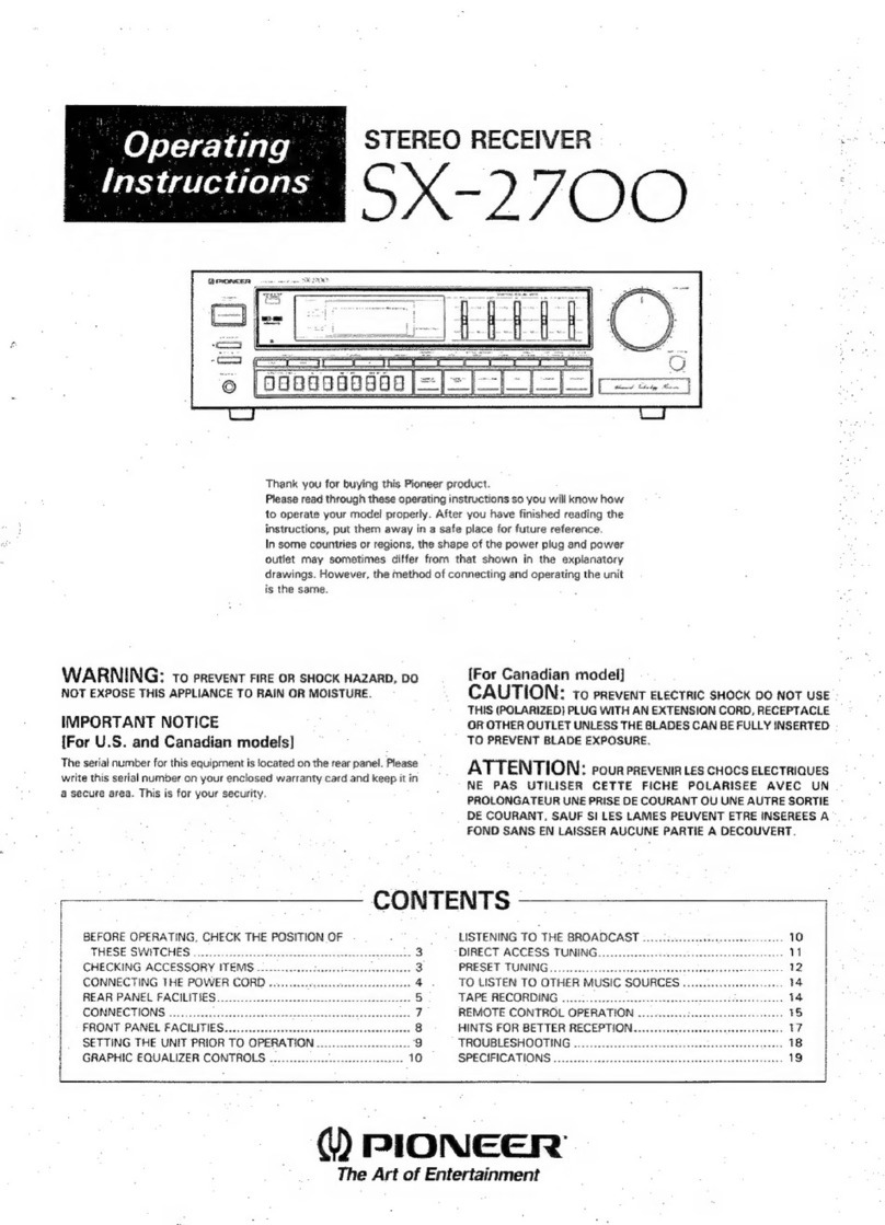
  9. Pioneer RX-1180 User manual

Pioneer RX-1180 User manual

Other manuals for RX-1180

1

This manual suits for next models

3

Other Pioneer Stereo Receiver manuals

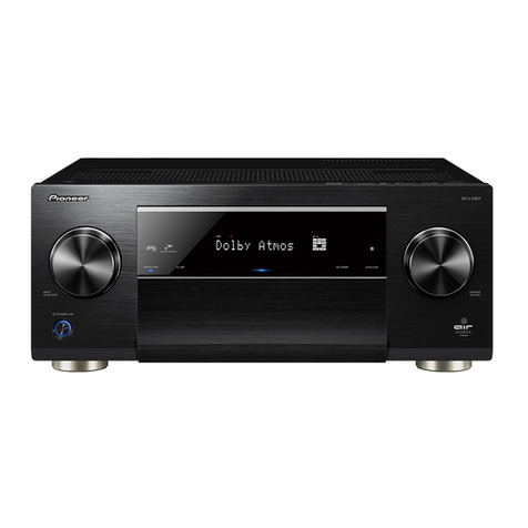
Pioneer SC-LX904 Manual

Pioneer

Pioneer SC-LX904 Manual

Pioneer DMH-1500NEX User manual

Pioneer

Pioneer DMH-1500NEX User manual

Pioneer VSX-1015TX User manual

Pioneer

Pioneer VSX-1015TX User manual

Pioneer VSX-425 User manual

Pioneer

Pioneer VSX-425 User manual

Pioneer VSX-453 User manual

Pioneer

Pioneer VSX-453 User manual

Pioneer AVH-X5850BT User manual

Pioneer

Pioneer AVH-X5850BT User manual

Pioneer AVH-200EX User manual

Pioneer

Pioneer AVH-200EX User manual

Pioneer VSX1017TXV User manual

Pioneer

Pioneer VSX1017TXV User manual

Pioneer DMH-Z5290BT User manual

Pioneer

Pioneer DMH-Z5290BT User manual

Pioneer VSX-5231 User manual

Pioneer

Pioneer VSX-5231 User manual

Pioneer DMH-100BT User manual

Pioneer

Pioneer DMH-100BT User manual

Pioneer SX-990 Setup guide

Pioneer

Pioneer SX-990 Setup guide

Pioneer DMH-2770NEX User manual

Pioneer

Pioneer DMH-2770NEX User manual

Pioneer VSX-D908S User manual

Pioneer

Pioneer VSX-D908S User manual

Pioneer Siriusxm DMH-2660NEX User manual

Pioneer

Pioneer Siriusxm DMH-2660NEX User manual

Pioneer SX-939 User manual

Pioneer

Pioneer SX-939 User manual

Pioneer VSX-535 User manual

Pioneer

Pioneer VSX-535 User manual

Pioneer DMH-G225BT User manual

Pioneer

Pioneer DMH-G225BT User manual

Pioneer AVH-2350DVD User manual

Pioneer

Pioneer AVH-2350DVD User manual

Pioneer Elite VSX-31 User manual

Pioneer

Pioneer Elite VSX-31 User manual

Pioneer XR-P160 User manual

Pioneer

Pioneer XR-P160 User manual

Pioneer SX-850 User manual

Pioneer

Pioneer SX-850 User manual

Pioneer AVH-P6300BT/XNUC User manual

Pioneer

Pioneer AVH-P6300BT/XNUC User manual

Pioneer DMH-ZS9350BT Use and care manual
Pioneer

Pioneer DMH-ZS9350BT Use and care manual

Popular Stereo Receiver manuals by other brands

Teac AG-680 Service manual

Teac

Teac AG-680 Service manual

Kenwood KR-V888D instruction manual

Kenwood

Kenwood KR-V888D instruction manual

Teac AGV1050 owner's manual

Teac

Teac AGV1050 owner's manual

Sony STR-435 operating instructions

Sony

Sony STR-435 operating instructions

Marantz CINEMA 70S owner's manual

Marantz

Marantz CINEMA 70S owner's manual

Kenwood KMDX92 instruction manual

Kenwood

Kenwood KMDX92 instruction manual

Yamaha RX-830 owner's manual

Yamaha

Yamaha RX-830 owner's manual

Denon AVR-1311 owner's manual

Denon

Denon AVR-1311 owner's manual

Denon AVR-S760H owner's manual

Denon

Denon AVR-S760H owner's manual

Denon AVR-X7200W Service manual

Denon

Denon AVR-X7200W Service manual

Sony XAV-1500 operating instructions

Sony

Sony XAV-1500 operating instructions

Radio Shack DX-399 owner's manual

Radio Shack

Radio Shack DX-399 owner's manual

Sony STR-DE535 - Fm Stereo/fm-am Receiver operating instructions

Sony

Sony STR-DE535 - Fm Stereo/fm-am Receiver operating instructions

Yamaha MusicCast TSR-5B3D owner's manual

Yamaha

Yamaha MusicCast TSR-5B3D owner's manual

Sony STR-DG500 - Multi Channel Av Receiver Service manual

Sony

Sony STR-DG500 - Multi Channel Av Receiver Service manual

Sherwood Newcastle RX-770 operating instructions

Sherwood

Sherwood Newcastle RX-770 operating instructions

Panasonic AJSD955B - DVCPRO50 STUDIO DECK Brochure & specs

Panasonic

Panasonic AJSD955B - DVCPRO50 STUDIO DECK Brochure & specs

Sherwood S-2660CP operation instruction

Sherwood

Sherwood S-2660CP operation instruction

manuals.online logo
manuals.online logoBrands
  • About & Mission
  • Contact us
  • Privacy Policy
  • Terms and Conditions

Copyright 2025 Manuals.Online. All Rights Reserved.

Operating
Instructions
Thank
you
for
buying
this
Pioneer
product.
Please
read
through
these
operating
instructions
so
you
will
know
how
to
operate
your
model
properly.
After
you
have
fin-
ished
reading
the
instructions,
put
them
away
in
a
safe
place
for
future
reference.
In
some
countries
or
regions,
the
shape
of
the
power
piug
and
power
outlet
may
sometimes
differ
from
that
shown
in
the
explanatory
drawings.
However,
the
method
of
connecting
and
operating
the
unit
is
the
same.
WARNING:
to
prevent
Fine
OR
SHOCK
HAZARD,
DO
NOT
EXPOSE
THIS
APPLIANCE
TO
RAIN
OR
MOISTURE.
IMPORTANT
NOTICE
[For
U.S.
and
Canadian
models]
The
serial
number
for
this
equipment
is
located
on
the
rear
panel.
Please
write
this
serial
number
on
your
enclosed
war-
ranty
card
and
keep
in
a
secure
area.
This
is
for
your
security.
[For
Canadian
model]
CAUTION:
to
prevent
ELECTRIC
SHOCK
DO
NOT
USE
THIS
(POLARIZED)
PLUG
WITH
AN
EXTENSION
CORD,
RECEPTACLE
OR
OTHER
OUTLET UNLESS
THE
BLADES
CAN
BE
FULLY
INSERTED
TO
PREVENT
BLADE
EXPOSURE.
ATTENTION:
pour
prevenin
Les
cHOcs
ELEC-
TRIQUES
NE
PAS
UTILISER
CETTE
FICHE
POLARISEE
AVEC
UN
PROLONGATEUR
UNE
PRISE
DE
COURANT
OU
UNE
AUTRE
SORTIE
DE
COURANT,
SAUF
SI
LES
LAMES
PEUVENT
ETRE
INSEREES
A
FOND
SANS
EN
LAISSER
AUCUNE
PARTIE
A
DECOUVERT.
TWO
VOLTAGE
SELECTOR
SWITCHES
Only
multi-voltage
models
are
provided
with
these
switches.
U.S.
and
Canadian
models
are
not
provided
with
these
switches.
Mains
voltages
in
Saudi
Arabia
are
127
V
and
220
V
only.
Never
use
this
model
with
110
V
setting
in
Saudi
Arabia.
The
line
voltage
selector
switches
are
on
the
rear
panel.
Before
|
FEATURES
CHECKING
ACCESSORY
ITEMS.
BEFORE
OPERATION
ANTENNA
CONNECTIONS
CONNECTIONS
PANEL
FACILITIES
REMOTE
CONTROL
UNIT
FACILITIES
TURNTABLE
FACILITIES
|
HOW
TO
HANDLE
CASSETTE
TAPES
.
|
GRAPHIC
EQUALIZER
CONTROLS
.........eeceeeeee
12
CONTENTS
STEREO
CASSETTE
DECK
RECEIVER
RX-1180/RX-1190
STEREO
TURNTABLE
PL-777AZ/PL-B8882Z
The
Model
PL-888Z
is
not
soid
in
the
U.S.A.
and
Canada.
your
model
is
shipped
from
the
factory,
these
switches
are
set
to
the
power
requirements
of
the
destination.
Check
they
are
set
properly
before
plugging
the
power
cord
into
the
house-
hold
wall
socket.
{f
the
voltage
is
not
properly
set
or
if
you
move
to
an
area
where
the
voltage
requirements
differ,
adjust
the
selector
switches
as
follows.
1.
Use
a
medium-size
screwdriver.
2.
First,
insert
a
screwdriver
into
the
groove
of
the
voltage
selector
at
the
top,
and
adjust
so
that
the
tip
of
the
groove
points
to
the
voltage
value
of
your
area.
3.
Next,
insert
a
screwdriver
into
the
groove
of
the
voltage
selector
at
the
bottom
and
adjust
until
the
voltage
is
the
same
as
at
the
top.
Both
switches
must
be
in
the
same
switch
setting.
@
Hove
tev
>
ov~240v
CHANNEL
STEP/FM
DE-EMPHASIS
SWITCH
Only
multi-voltage
models
are
provided
with
these
switches.
U.S.
and
Canadian
models
are
not
provided
with
these
switches.
The
unit
has
been
factory
preset
to
the
channel
allocation
and
de-emphasis
value
for
the
area
in
which
it
is
to
be
sold.
If
these
value
are
set
incorrectly,
the
frequency
display
may
stop
at
the
wrong
frequency,
or
sound
may
be
distorted,
resulting
in
an
inability
to
reproduce
reception
signals
at
their
proper
sound
quality.
For
this
reason,
be
sure
to
confirm
that
the
values
are
set
correctly
before
first
using
the
unit.
{100
kHz/10 kHz/75
ys]
position:
Set
to
this
position
for
areas
with
FM
reception
step
of
100
kHz,
AM
10
kHz,
and
de-emphasis
75
xs.
[50
KHz/9
kHz/50
us]
position:
Set
to
this
position,
for
areas
with
FM
reception
step
of
50
kHz,
AM
9
kHz,
and
de-emphasis
of
50
us.
When
unsure
about
the
channel
allocation
and
de-emphasis
values
for
your
area,
con-
sult
your
dealer
for
correct
information.
DE-EMPHASIS
100/10
kHz
|
PRELIMINARY
OPERATIONS.
BASIC
OPERATIONS
...
TAPE
COPYING
RECORDING
AND
PLAYBACK
USING
THE
AUDIO
TIMER.......0.000..-
eee
16
MIC
MIXING
MAINTENANCE
TROUBLESHOOTING
SPECIFICATIONS
®Q
PIONEER’
The
future
of
sound
and
vision.
READ
INSTRUCTIONS
—
All
the
safety
and
operating
instructions
should
be
read
before
the
appliance
is
operated
RETAIN
INSTRUCTIONS
—
The
operating
instruc-
tions
should
be
retained
for
future
reference.
HEED
WARNING
—
All
warnings
on
the
appliance
and
in
the
operating
instructions
should
be
adhered
to.
FOLLOW
INSTRUCTIONS
—
All
operating
and
use
instructions
should
be
followed
WATER
AND
MOISTURE
—
The
appliance
should
not
be
used
meer
water
—
for
example,
near
a
bathtub,
washbow!,
kitchen
sink,
laundry
tub,
ina
wet
basement,
or
near
a
swimming
pool,
etc.
LOCATION
—
The
appliance
should
be
instalfed
in
0
stable
location.
WALL
OR
CEILING
MOUNTING
—
The
appliance
should
not
be
mounted
to
a
wall
or
ceiling
pliance
should
not
be
situated
on
a
bad,
sofa,
rug,
or
similar
surface
that
may
block
the
ventilation
openings;
or,
placed
in
a
built-in
installation,
such
as
a
bookcase
or
cabinet
thet
may
impede
the
flow
of
air
through
the
ventilation
openings.
HEAT
—
The
appliance
should
be
situated
away
from
heat
sources
such
as
radiators,
heat
registers,
stoves,
or
other
appliances
(including
amplifiers)
that
produce
heat
POWER
SOURCES
—The
appliance
should
be
connected
to
a
power
supply
only
of
the
type
described
in
the
operating
instructions
or
as
marked
on
the
appliance.
POWER-CORD
PROTECTION
—
Power-supply
cords
should
be
routed
so
that
they
are
not
likely
to
be
walked
on
or
pinched
by
items
placed
upon
or
against
them,
paying
particular
attention
to
cords
at
plugs,
convenience
receptacies,
and
the
point
where
they
exit
from
the
appliance.
POLARIZATION
—
If
your
purchased
product
is
provided
with
a
polarized
power
plug,
please
read
the
following
instructions.
This
product
is
equipped
with
2
polarized
alternating
current
line
plug
(a
plug
having
one
blade
wider
than
the
other).
This
plug
will
fit
into
the
power
outlet
only
one
way.
This
is
a
safety
feature,
If
you
are
unable
to
insert
the
plug
fully
into
the
outlet,
try
reversing
SERVICE
ENTRANCE
EQUIPMENT
POWER
LINES
—
An
outdoor
antenna
should
be
located
away
from
power
fines.
NONUSE
PERIODS—The
power
cord
of
the
appliance
should
be
unptugged
from
the
outlet
when
left
unused
for
2
long
period
of
time.
OBJECT
AND
LIQUID
ENTRY
—
Care
shouid
be
taken
so
that
objects
do
not
fall
and
liquids
are
not
spilled
into
the
enclosure
through
openings.
DAMAGE
REQUIRING
SERVICE
—
The
appliance
should
be
serviced
by
a
Pioneer
authorized
ser-
vice
center
or
qualified
service
personnel
when:
©
The
power-supply
cord
or
the
plug
has
been
damaged;
or
®
Objects
have
fallen,
or
liquid
has
been
spilled
into
the
appliance:
or
©
The
appliance
has
been
exposed
to
rain;
or
®
The
appliance
does
not
sppear
to
operate
nor-
maliy
or
exhibits
2
marked
change
in
perfor-
VENTILATION
—
The
appliance
should
be
situated
mance;
or
so
that
its
location
or
position
does
not
interfere
®
The
appliance
has
been
dropped;
or
the
enclosure
with
its
proper
ventilation.
For
example,
the ap-
damaged.
SERVICING—~The
user
should
not
attempt
to
service
the
appliance
beyond
that
described
in
the
Operating
instructions.
For
all
other
servicing,
contact
the
nearest
Pioneer
authorized
service
center.
POWER
LINES
SERVICE
“
ENTRANCE
CONDUCTORS,
GROUND
GROUND
WIRE
ab
CLAMPS
SAFETY
INSTRUCTIONS
—
u
7
DI
ANTENNA
|
ROUNDING
tet
to
provide
some
protection
against
voltage
surges
and
buiit
up
static
charges
in
the
U.S.A.
section
810
of
the
National
Eles-
trical
Code,
ANSI/NFPA
No.
70-1884,
provides
information
with
respect
to
proper
grounding
of
the
mast
and
supporting
structure,
grounding
of
the
lead-in
wire
to
an
antenna
discharge
unit,
size
of
grounding
‘conductors,
location
of
antenna
discharge
unit,
connection
to
grounding
eles
trodes,
and
requirements
for
the
grounding
elec-
trode.
See
Fig.
A.
a)
Use
No.
10
AWG
(5.3
mm?)
cop-
per,
No.
8
AWG
(8.4
mm?)
alu-
minum,
No.
17
AWG
(1.0
mm2}
copperclad
steel,
bronze
wire,
or
larger
as
ground
wire.
b)
Secure
antenna
lead-in
and
ground
wires
to
house
with
stand-off
insulators
spaced
from
4
feet
(1.22
meters)
to
6
feet
(1.83
meters)
apart,
c)
Mount
antenna
discharge
unit
as
closely
as
possible
to
where
lead-
in
enters
house.
STAND-OFF_
d)
Use
jumper
wire
not
smailer
than
NSUEATORS'®
No.6
AWG
(13.3
mm*)
copper,
or
the
equivalent,
when
a
sepa-
rate
antenna-grounding
electrode
is
used.
See
NEC
Section
810-21
{j).
EAD-IN
WIRE
TO
EXTERNAL
ANTENNA
ERMINALS
OF
PRODUCT
ANTENNA
SCHARGE
UNIT
¢
GROUND
the
plug,
If
the
plug
should
still
fail
to
fit,
contact
WIRE
ob
your
electrician
to
replace
your
obsolete
outlet
ae
not
defeat
the
safety
purpose
of
the
polarized
a
GROUND
plug,
;
POWER
SERVICE
ES
CLAMPS
CLEANING
—
The
appliance
should
be
cleaned
only
—
GROUNDING
ELECTRODE
SYSTEM
Antal
conowa
ARNE
|
with
a
polishing
cloth
or
a
soft
dry
cloth.
Never
(2.8:
interior
moral
water
pipe)
fi
clean
with
furniture
wax,
benzine,
insecticides
or
other
volatile
liquids
since
they
may
corrode
the
UIRED
BY
cabinet
FIG.A
H
LOCAL
CODES
See
MU
NEC
SECTION
810-21
(1).
IMPORTANT
1
The
lightning
flash
with
arrowhead,
within
an
equilateral
triangle,
is
intended
to
alert
the
user
of
the
presence
of
uninsulated
“dangerous
voltage”
within
the
product's
enclosure
that
may
be
of
sufficient
magnitude
to
constitute
a
risk
of
electric
shock
to
persons.
IMPORTANT
2
if
the
apparatus
is
fitted
with
AC
mains
power
outlet(s},
see
REAR
PANEL
FACILITIES
for
convenient
connec-
tion
of
additional
Hi-Fi
componentis}.
Make
alf
connec-
tions
to
the
AC
outletis}
and
the
signal
terminals
first.
Connect
the
plug
to
the
wall
socket
last,
make
sure
that
the
power
switch
is
off.
Disconnect
the
wail
plug
when
the
equipment
is
not
in
(regular)
use,
e.g.
when
on
vacation,
2
<ARBIO57>
db
BonciNG
=
1
JUMPERG
oo)
FR
CAUTION
RISK
OF
ELECTRIC
SHOCK
OO
NOT
OPEN
CAUTION:
TO
PREVENT
THE
RISK
OF
ELECTRIC
SHOCK,
DO
NOT
REMOVE
COVER
(OR
BACK).
NO
USER-
SERVICEABLE
PARTS
INSIDE.
REFER
SERVIC-
ING
TO
QUALIFIED
SERVICE
PERSONNEL.
FOR USE
IN
THE
UNITED
KINGDOM
‘The
wires
in
this
mains
lead
are
coloured
in
accordance
with
the
following
code:
Blue:
Neutrat
Brown:
Live
GROUNDING
ELECTRODE
DRIVEN
8
FEET
(2.44
m)
INTO
THE
EARTH
The
exclamation
point
within
an
equilateral
triangle
is
intended
to
alert
the
user
of
the
presence
of
important
operating
and
maintenance
(servicing)
instructions
in
the
literature
accompanying
the
appliance.
As
the
colours
of
the
wires
in
the
mains
lead
of
this
ap-
paratus
may
not
correspond
with
the
coloured
marking
identifying
the
terminais
in
your
plug
proceed
as
follows:
The
wire
which
is
coloured
blue
must
be
connected
to
the
terminal
which
is
marked
with
the
letter
N
or
col-
oured
black.
‘The
wire
which
is
coloured
brown
must
be
connected
to
the
terminal
which
is
marked
with
the
letter
L
or
col
oured
red.
Equipment
sold
in
the
U.K.
is
not
supplied
with
a
power
plug.
FEATURES
BEFORE
OPERATION
High
power
output
5
band
graphic
equalizer
System
remote
contro!
=
Stereo
double
cassette
tape
deck
Synchronized
recording
start
High
speed
copy
Relay
play
Auto
tape
selector
Auto
recording
fevel
Quartz
PLL
synthesizer
FM/AM
tuner
Up
to
24
stations
random
pre-set
CHECKING
ACCESSORY
ITEMS
®
Size
“AAA”
(IEC
RO3)
1.5V
(UM-4)
dry
cell
batteries
@
Remote
control
unit
=e
°
FM
T-type
antenna
BEFORE
OPERATION
REMOTE
CONTROL
UNIT
¢
AM
loop
antenna
[1]
Remove
the
cover
of
the
battery
compartment
on
the
reverse
side
of
the
remote
control
unit.
[2]
Take
out
the
two
size
“AAA”
[IEC
RO3
(UM-4)]
dry
cell
batteries
supplied
and
load
them
into
the
battery
compartment,
taking
care
to
follow
the
markings
on
the
compartment.
[3]
Replace
the
cover
of
the
battery
compartment.
Cautions
for
handling
dry
cell
batteries.
Misusing
dry
cell
batteries
can
result
in
electrolyte
leakage
or
explo-
sions.
Bear
in
mind
the
following
points
for
getting
the
most
out
of
your
batteries.
@
When
loading
the
batteries
into
the
battery
compartment,
make
sure
the
plus
®
and
minus
©
polarities
correspond
to
the
mark-
ings
on
the
compartment.
@
Even
though
they
may
be
the
same
shape,
batteries
come
with
different
voltage
ratings.
Do
not
mix
or
use
different
types
of
bat-
teries
together.
Use
only
the
same
kind
of
batteries.
@
Do
not
mix
up
new
batteries
and
used
batteries
but
replace
ali
the
batteries
at
the
same
time.
@
Do
not
heat
up,
disassemble
or
shortcircuit
batteries
or
throw
them
into
a
fire.
@
Some
batteries
are
rechargeable
while
others
are
not.
Observe
the
cautionary
notes
on
the
batteries
and
use
them
properly.
TURNTABLE
PL-8882Z,
PL-777AZ
INITIAL
TURNTABLE
SET-UP
Note:
H
The
PL-777
AZ
is
not
equipped
with
a
dust
cover.
}
1
«
Check
the
accessories.
S
EP
adaptor
Platter
mat
2
s
Remove
the
two
clampers
and
the
platter.
After
turning
the
clampers
in
the
direction
shown
in
the
diagram,
remove
by
lifting
up.
Clampers
3
»
Engage
the
belt
on
the
back
of
the
platter
with
the
fingers.
4
a
Install
the
platter
on
the
platter
shaft
and
engage
the
belt
on
the
motor
pulley.
Slowly
rotate
the
platter
by
hand
and
make
sure
the
belt
is
correctly
engaged
on
the
motor
pulley
as
shown
in
the
diagram.
Platter
mat
5
=
Place
the
platter
mat
on
the
platter.
6
s
Remove
the
vinyl
band
holding
the
tonearm.
7
=
Remove
the
tonearm
from
the
arm
rest.
o>
P
8
=
Remove
the
stylus
cover.
is
<ARB1057>
ANTENNA
CONNECTIONS
RADIO
RECEPTION
IS
NOT
POSSIBLE
UNLESS
THE
ANTENNA
IS
PROPERLY
CONNECTED.
The
strength
of
broadcast
signal
varies
from
one
area
to
another
(signal
propagation
is
especially
poor
in
metropolitan
areas,
where
there
are
may
tall
buildings,
and
in
mountainous
areas}.
Proper
antenna
installation
is
vital
to
good
reception.
AM
ANTENNA
The
AM
loop
antenna
supplied
with
the
cassette
deck
receiver
should
be
connected
to
the
AM
antenna
terminals.
The
antenna
should
be
placed
at
a
distance
from
the
cassette
deck
receiver,
and
should
not
be
allowed
to
touch
metallic
objects.
Avoid
placing
it
near
CD
players,
personal
computers,
televi-
sion
sets,
and
other
devices
generating
radio
frequencies.
Setting
up
the
AM
antenna
®
Fold
out
the
supports
on
the
bottom
of
the
antenna.
Insert
the
stopper
in
the
hole
in
the
antenna
to
lock
them
in
place.
°
Place
the
antenna
on
a
level
surface
and
rotate
it
to
locate
the
orientation
that
yields
the
best
reception.
AM
Loop
Antenna
Set-up
Hole
Stopper
AM
Loop
Antenna
Connection
The
accessory
AM
loop
antenna
must
be
connected
to
ensure
proper
reception.
External
AM
antenna
Indoor
AM
antenna
Provide
a
vinyl-coated
wire
(5
to
6
meters
long).
Secure
one
end
to
the
AM
terminal
and
the
other
end
to
a
wall
or
other
high
location.
Outdoor
AM
antenna
If
reception
is
still
poor
even
when
a
lead
antenna
has
been
stretched
out
indoors,
stretch out
a
vinyl-coated
wire
and
se-
cure
it
outdoors.
Connecting
the
external
AM
antenna
Outdoor
AM
antenna
AM
{oop
antenna
(
\
indoor
AM
antennal
NOTE:
Do
net
detach
the
AM
loop
antenna
when
using
the
external
AM
antenna.
A
<ARBI057>
FM
ANTENNA
FM
T-type
antenna
attachment
Connect
the
accessory
FM
T-type
antenna
to
the
FM
termi-
nals.
Stretch
the
antenna
out
to
its
full
length,
and
affix
it
to
a
wall,
etc.
Stretch
out
both
ends.
(_—
Correct
Wrong
Wrong
The
accessory
FM
T-type
antenna
must
be
connect
to
ensure
proper
reception.
ye
()
(e)
External
FM
antenna
installation
Use
an
external
antenna
when
the
signals
from
the
station
are
weak
and
cannot
be
picked
up
by
the
accessory
FM
T-type
antenna,
or
when
the
sound
heard
is
accompanied
by
large
amounts
of
noise.
There
are
two
ways
of
connecting
the
external
FM
antenna
to
the
ANTENNA
terminals
with
3000
feeder
wire,
or
with
a
75@
coaxial
cable.
It
is
recommended
that
you
use
the
752
coaxial
cable,
so
that
the
effects
of
extraneous
noise
are
reduced
to
a
minimum.
When
the
connecting
cable
is
a
752
coaxial
cable
750
coaxial
cable
When
the
connecting
cable
is
a
30092
feeder
wire
3002
feeder
le)
CONNECTIONS
Proceed
as
follows
with
the
set-up
and
connections
1
Connect
the
FM
antenna
and
the
AM
antenna
to
the
cassette
deck
receiver's
ANTENNA
terminals.
(See
page
4}
|
{Use
an
antenna
ground
as
necessary.
See
page
6.)
|
|
2,
Connect
the
turntable’s
cords
to
the
cassette
deck
receiver's
TURNTABLE
jacks
(and
GND
terminai*).
If
any
other
stereo
component
is
'
to
be
used,
connect
in
the
same
way
to
the
cassette
deck
receiver‘s
input
jacks.
3.
Connect
the
speaker
cords
to
the
SPEAKERS
terminals.
*
U.S.
RX-1180
model
do
not
have
a
GND
terminal.
4,
Finally,
connect
the
power
cord
to
the
AC
wall
socket.
The
illustration
does
not
conform
to
U.S.
RX-1180
model.
Connecting
the
input/output
R
L
AM
<<
cords
(
—
a
|
Red
plug
ag
ae
eal
White
plug
loop
|
antenna
FM
T-type
antenna
*
Connect
the
plugs
properly.
Faulty
connections
can
cause
noise
and
also
breakdowns
and
failures.
°
The
white
terminal
is
for
the
left
channel
and
the
red
f
|
terminal
is
for
the
right
channel.
Connecting
the
speaker
cords.
Turntable
Cutter
2
Serer
|
Speaker
cord
1
:
L
|
Twist
the
strands.
10
mm
When
using
snother
turntable
When
using
3
Push
toward
4
Push
toward
tntne
es
the
outside
the
inside
Se
To
AC
wall
socket
©
|.
©
©
Speaker
system
B
L
channel
R
channel
LaserVision
player
CD
player
or
VCR
etc.
/
‘To
cassette
deck
receiver's
AC
OUTLET
5
<ARB1057>
CONNECTIONS
Antenna
ground
Although
grounding
is
not
necessary
for
reception
it
is
recom-
mended
for
protection
against
damage
from
lightning
if
an
out-
door
FM
antenna
is
used.
Grounding
is
recommended
as
well
to
help
reduce
noise
and
hum.
NOTE:
Never
make
the
ground
connection
to
a
gas
pipe
as
sparks
could
cause
the
gas
to
ignite.
N
°
OTE
ABOUT
SPEAKER
CONNECTIONS
Speaker
systems
used
should
have
an
impedance
of
be-
tween
82
and
162.
Be
sure
that
connections
are
secure.
Check
to
make
sure
that
wires
do
not
protrude
from
their
terminals.
Do
not
allow
the
speaker
cords
to
become
shorted.
Damage
may
result
to
your
equipment.
e
Do
not
attempt
to
simultaneously
connect
two
sets
of
speakers
to
a
single
side
(A
or
B).
When
using
two
sets
of
speakers,
connect
one
set
to
side
A
and
one
set
to
side
B.
AC
OUTLET
SWITCHED
100W
MAX
Power
supplied
through
this
outlet
is
turned
on
and
off
by
this
equipment’s
POWER
switch.
Total
électrical
power
consump-
tion
of
connected
equipment
should
not
exceed
100
W.
NOTE:
Do
not
connect
appliances
with
high
power
consumption
such
as
heaters,
irons,
or
television
sets
to
the
AC
OUTLET,
in
order
to
avoid
overheating
or
fire
risk.
This
can
cause
this
equipment
to
malfunction.
To
control
a
unit
other
than
this
receiver
using
the
re-
mote
control
unit
@
In
the
case
of
a
PIONEER
equipment
marked
sR
which
is
provided
with
a
remote
sensor,
operate
the
equipment
by
aiming
the
remote
control
unit
at
the
remote
sensor
on
the
equipment.
@
For
equipment
with
the
&!
mark,
but
without
a
remote
sensor,
operation
of
the
equipment
by
facing
the
remote
con-
trol
unit
towards
the
remote
sensor
of
the
cassette
deck
receiv-
er
possible
with
connection
from
the
CONTROL
OUT
jack
to
the
CONTROL
IN
jack.
Use
a
commercially
available
cable
with
mini-plugs
for
the
connection.
PANEL
FACILITIES
6
IN
out
CONTROL
c
aa
out
CONTROL
CONTROL
IN
S
eye}
@
<n
(o
CD
player
Equipment
with
aie
Q
the
gi]
mark.
Cassette
deck
receiver
@
<ARB1057>
PANEL
FACILITIES
TUNER
SECTION
STATION
CALL
switches
These
are
used
to
recall
preset
broadcasting
stations
and
to
preset
the
station.
@FREQUENCY/STATION
NUMBER
DISPLAY
@INDICATORS
{TUNED}
This
lights
to
indicate
that
a
station
has
been
optimally
tuned
in.
[STEREO]
This
lights
during
FM
stereo
reception
[FM
MONO]
Lights
when
the
FM
MONO
switch
is
pressed
to
select
monaural
FM
reception.
{AUTO
TUNING]
Lights
when
the
auto
tuning
mode
is
selected
during
FM/AM
reception.
@MEMORY
switch
This
switch
is
used
to
mermorize
stations.
When
the
switch
is
pressed,
the
FREQUENCY
indicator
will
flash.
To
raemorize
the
frequency
of
any
station,
press
the
STATION
CALL.
switch
while
the
frequency
indicator
is
flashing
©@FM
MONO
switch
Normally,
the
FM
MONO
indicator
remains
off.
However,
it
may
not
be
possible
to
tune
in
a
desired
FM
station
because
it
is
too
far
away
or
because
its
signals
are
too
weak.
In
cases
like
these,
press
the
switch
to
set
the
reception
to
the
mon-
aural
mode
(FM
MONDO
indicator
lights)
and
tune
in
the
station.
The
program
of
an
FM
stereo
broadcast
will
be
heard
iy
mono.
This
switch
will
not
function
for
AM
reception.
@AUTO/MANUAL
switch
Use
to
select
either
the
AUTO
mode
or
MANUAL
mode
for
FM/AM
reception.
TUNING
switch
(—,
+)
The
function
of
this
switch
differs
according
to
whether
AUTO
tuning
or
MANUAL
tuning
is
selected.
[AUTO
tuning
mode]
When
this
mode
is
selected,
AUTO
TUNING
indicator
light
(press
AUTO/MANUAL
switch
if
the
indication
is
not
lighting),
When
the
“
+’
switch
is
pressed,
the
frequencies
are
scanned
in
ascending
order;
when
the
“’
—’’
switch
is
pressed,
they
are
scanned
in
descending
order.
Scanning
stops
a5
Soon
as
a
sta
tion
has
automatically
been
tuned
in.
Auto
scanning
is
terminated
when
either
TUNING
(~,
+},
AUTO/MANUAL,
BAND,
or
MEMORY
switch
Is
pressed.
(MANUAL
tuning
mode]
When
this
mode
is
selected,
AUTO
TUNING
indicator
turns
off
(press
AUTO/MANUAL
switch
if
the
indicator
is
lighting).
When
the
“+
switch
is
kept
pressed,
the
frequency
increases
and
when
the
““—’’
switch
is
kept
pressed,
it
decreases.
@BAND
selector
switch
(FM/AM)
This
is
used
to
select
the
band
of
the
desired
station.
The
bands
change
alternately
each
time
the
switch
is
pressed.
[>
FM
reception
-~AM
reception
ee ee
AMPLIFIER
SECTION
@POWER
(STANDBY/ON)
switch
When
this
switch
is
set
to
the
ON
position,
the
STAND-
BY/SLEEP
indicator
goes
out
and
power
is
supplied
to
the
main
circuits
of
the
cassette
deck
receiver.
Disconnect
the
power
cord from
the
power
outlet
when
you
do
not
plan
to
use
the
cassette
deck
receiver
for
a
long
period
of
time.
The
cassette
deck
receiver
has
a
backup
function,
so
it
will
return
to
the
original
status
when
the
power
cord
is
unplugged
and
soon
i
again
plugged
into
the
power
outlet.
@STANDBY/SLEEP
indicator
This
indicator
lights
in
stand-by
status
or
when
the
SLEEP
function
is
operating
when
the
power
cord
is
connected
to
a
power
outlet.
When
the
SLEEP
key
on
the
remote
control
unit
is
pressed,
the
sleep
function
activated
for
approximately
60
minutes,
then
enters
the
standby
mode.
(The
SLEEP
indicator
flashes
faster
as
the
end
of
the
remaining
time
nears.)
@)
PHONES
jack
This
is
a
‘standard
plug-type
jack”
for
headphones.
NOTE:
Sound
is
not
heard
from
the
speakers
when
headphones
are
in
i
use.
@SPEAKERS
switch
(
@
A,
=
A+B)
This
is
used
to
select
the
speaker through
which
you
wish
to
listen.
HA
:
When
the
speakers
connected
to
A
terminals
are
in
use.
=
A+B
:
When
the
speakers
connected
to
A
and
B
ter-
minals
are
in
use.
(There
is
no
sound
if
A
+
Bis
selected
when
speakers
are
connected
only
to
the
A
terminals.)
Be
sure
to
use
A
terminals
when
you
use
a
pair
of
speakers
only.
No
sound
will
be
heard
through
the
speakers
when
only
a
pair
of
speakers
are
connected
to
B
terminals.
(GRAPHIC
EQUALIZER
controls
The
equalizer
is
divided
into
five
frequency
ranges
(100
Hz,
330
Hz,
1
kHz,
3.3
kHz,
10
kHz)
to
tailor
music
to
the
individual
taste
of
the
listener.
NOTE:
Effective
only
for
audio
playback.
Does
not
work
for
recording
and
copying
operations.
7
<ARB1057>
PANEL
FACILITIES
(FUNCTION
switches/indicators
The
indicators
light
for
the
specified
functions.
[VIDEO/AUX]
Press
when
listening
to
a
stereo
component
connected
to
the
VIDEO/AUX
jacks.
{TAPE]
Press
when
listening
to
a
cassette
tape.
(TUNER]
Press
when
listening
to
a
radio
broadcast.
[PHONO]
Press
when
playing
records
on
a
turntable
connected
to
the
PHONO
jacks.
[CD]
Press
when
listening
to
a
CD
player
connected
to
the
CD
jacks.
(REMOTE
SENSOR
window
(@®VOLUME/BALANCE
indicator
The
indicator
shows
volume
Jevel.
When
either
of
BALANCE
switches
is
pressed,
the
indicator
shows
BALANCE
between
left
and
right
channels.
The
indicator
flashes
during
muting.
@VOLUME
switch
This
switch
is
pressed
to
adjust
the
volume.
+:
Increases
volume.
—:
Decreases
volume.
BALANCE
switches
Use
to
adjust
the
balance
between
the
sounds
from
the
left
and
right
speakers.
L:
Press
to
decrease
the
sound
on
the
right
side.
R:
Press
to
decrease
the
sound
on
the
left
side.
CENTER:
The
display
returns
to
CENTER
when
both
L
and
R
are
pressed
simultaneously.
G2MUTING
switch
Pressing
this
switch
alternately
interrupts
and
returns
the
sound.
VOLUME/BALANCE
indicator
flashes
during
muting.
@MIC
jack
(excluding
U.S.
and
Canadian
modeis)
Used
to
connect
microphones
equipped
with
standard
plugs.
@)MIXING
LEVEL
(excluding
U.S.
and
Canadian
models)
Adjusts
the
volume
of
the
microphone.
Increasing
the
microphone
volume
reduces
the
source
volume.
CASSETTE
TAPE
DECK
SECTION
e
The
cassette
deck
receiver
is
provided
with
an
automatic
tape
selector
function.
Deck
|
.:.
NORMAL/CrO2,
METAL
Deck
II...
NORMAL/CrO2
8
<ARB1057>
@Deck
|
switches
/&ISTOP/EJECT)..
Stops
tape
travel.
Ejects
cassette
if
pressed
when
tape
is
stopped.
>
(PLAY)
.....--00.00
Playback.
be
(FF)...
..
Fast
forward
~<a
(REW)
..
Rewind
®Deck
Hl
switches
2
QO(PAUSE).......-...-
Temporarily
stops
tape
travel.
Can-
cels
pause
mode
when
pressed
again.
OAS
(STOP/EJECT)....
Stops
tape
travel.
Ejects
cassette
if
pressed
when
tape
is
stopped.
..
Playback
..
Fast
forward
..
Rewind
..
Set
to
the
recording
mode.
[>
(PLAY).
>
(FF)
~ea
(REW)..
@
(REC)...
@
DECK
ll
TAPE
COUNTER
3-digital
display
measures
tape
travel
on
deck
II.
@
DECK
Il
TAPE
COUNTER
RESET
button
@)Recording
indicator
(REC)
Lights
during
recording.
Flashes
during
tape
copy
standby
mode
or
remote
control
pause.
@
COPY
MODE
switches/indicators
These
switches
and
indicators
are
used
to
select
the
copy
mode.
SYNCHRO.........
Normal
speed
copying
(Permits
you
to
lis-
ten
to
playback
normally.)
HIGH
SPEED
.....
High
speed
copying
(double-speed,
half-
time
copying)
@
DOLBY
NR
switch/indicator
Press
to
activate
noise
reduction
system.
Use
to
play
back
tapes
recorded
using
Dolby
B
NR
noise
reduction.
¢
Tapes
recorded
using
Dolby
B
NR
noise
reduction
should
always
be
played
back
with
the
noise
reduction
system
on.
Sound
quality
will
be
adversely
affected
if
they
are
played
back
with
the
system
off,
or
if
tapes
recorded
using
a
differ-
ent
noise
reduction
system
are
played
back
with
the
Dolby
B
NR
system
on.
®
itis
recommended
that
tapes
recorded
using
Dolby
B
NR
be
so
marked
on
the
label.
This
will
help
to
prevent
incor-
rect
setting
of
the
noise
reduction
switch
during
playback.
Noise
reduction
manufactured
under
license
from
Dolby
Laboratories
Licensing
Corporation.
“Dolby’’
and
the
double-D
symbol
are
trademarks
of
Dolby
Laboratories
Licensing
Corporation.
REMOTE
CONTROL
UNIT
FACILITIES
Range
of
remote
control
When
the
remote
control
unit
is
pointed
at
the
REMOTE
SEN-
SOR
window
on
the
deck
receiver
and
any
of
its
keys
is
pressed,
the
cassette
deck
receiver
and
other
components
can
be
operated
by
remote
control.
Distance:
Within
a
range
of
about
7
meters
from
the
REMOTE
SENSOR
window
Angle:
Within
approx.
30
degrees
from
the
center
of
the
REMOTE
SENSOR
window
Remote
control
will
not
be
possible
if
there
is
an
obstacle
be-
tween
the
remote
control
unit
and
the
REMOTE
SENSOR
window.
SR
ote
es
PHONO
cS
ja
am
a4
—
we
o—
lhe
@
co
cOFUNC|
=
CONTROL
UNIT
|
a
=m
——
=i-—~@
CU-RX001
Q
PIONEER
Ed
@
POWER
key
@MUTING
key
@VOLUME
(DOWN,
UP)
key
@SLEEP
key
Pressing
this
key
sets
the
sleep
timer
to
approximately
60
minutes.
The
STANDBY/SLEEP
indicator
flashes
while
the
sleep
timer
is
operating.
The
SLEEP
indicator
flashes
faster
as
the
end
of
the
remaining
time
nears.
@®FUNCTION
selector
keys
®STATION
key
UP:
Used
to
tune
in
the
station
numbers
in
ascending
order.
DOWN:
Used
to
tune
in
the
station
numbers
in
descending
order.
@TAPE
PAUSE
key
;
Use
to
pause
during
tape
playback
or
recording.
Press
again
to
release
the
pause.
Refer
to
‘Remote
control
pause”’
for
details.
@CD
keys
>
(Play)...
.
Function
on
the
amplifier
section
is
set
to
CD
mode.
Begins
CD
playback.
§@
(Pause)..
.
Press
to
temporarily
pause
playback.
&
(Stop)
Press
to
stop
playback.
DISC..
.
Disc
numbers
can
be
selected
when
used
together
with
a
Pioneer
maga-
zine
type
CD
player.
.
When
pressed
once,
play
advances
to
the
beginning
of
the
next
track;
when
pressed
continuously,
ad-
vances
to
further
tracks.
.
When
pressed
once,
play
returns
to
the
beginning
of
the
currently
playing
track;
when
pressed
continuously,
returns
to
earlier
tracks.
»e1
(Track
search)
..
bea
(Track
search)
..
Remote
Controi
Pause
(When
remote
control
pause
is
possible)
Deck
1
Deck
fl
iRelay
Play}
Source
|
SYNCHRO
PLAY PLAY
REC.
REC.
Deck
|
YES
-
YES*
_**
YES***
Deck
Il
-
YES
YES*
YES
Yes***
*When
pause
is
applied
while
the
deck
is
playing
back.
**Use
remote
control
pause
only
for
Deck
Il
during
tape
dub-
bing.
The
Deck
Ii
pause
will
not
be
released
even
if
Deck
|
is
played
back
in
this
status.
***Both
Deck
|
and
Deck
Il
will
pause.
Pressing
the
remote
control
PAUSE
key
again
releases
the
pause.
NOTES:
*°
Remote
control
pause
is
also
released
when
the
deck
oper-
ating
status
is
changed
by
using
any
of
the
main
unit
operat-
ing
switches
except
for
the
Deck
If
PAUSE
switch
fexcept
for
item
**
above}.
When
pause
is
applied
from
the
remote
con-
|
trol,
it
is
recommended
that
the
pause
also
be
released
from
i
the
remote
control.
|
°
{fa
pause
is
applied
while
one
deck
is
playing
back,
the
pause
|
will
not
be
refeased
even
if
the
FF,
REW,
STOP/EJECT
|
|
switches
of
the
other
deck
are
operated.
{Pressing
the
PLAY
switch
releases
the
pause
and
enters
the
relay
playback
mode.}
<ARB1057>
TURNTABLE
FACILITIES
Illustration
shows
model
PL-888Z.
NOTE:
PL-777AZ
is
not
equipped
with
disc
size
switch
and
dust
cover.
@EP
adaptor
@Platter
shaft
@)Platter
mat
@)
Platter
(©)Dust
cover
©®Arm
rest
@Tonearm
®
Cartridge
@SPEED
switch
Set
this
switch
in
accordance
with
the
speed
of
the
record.
33:
For
33-1/3
rpm
records.
45:
For
45
rpm
records.
GO
ARM
ELEVATION
switch
@
Use
the
switch
for
manual
play.
¢
Use
the
switch
to
suspend
record
play
temporarily.
°
Use
the
switch
when
changing
the
tracks
during
actual
play.
[UP]
:
The
tonearm
rises
(the
stylus
moves
away
from
the
record}.
[DOWN]:
The
tonearm
descends
(the
stylus
is
lowered
onto
the
record).
10
<ARB1057>
@DISC
SIZE
switch
(only
PL-8882)
Set
this
switch
in
accordance
with
the
size
of
the record.
30:
For
30
cm
LP
records.
17:
For
17
cm
EP
records.
@START/STOP
switch
(only
PL-888Z)
Press
this
switch
when
starting
auto
play
or
when
stopping
play.
NOTE:
Be
sure
to
press
the
switch
firmly
when
starting
playback:
if
not
pressed
firmly,
the
platter
may
rotate
without
the
tonearm
moving.
@STOP
switch
(only
PL-777AZ)
Press
this
switch
when
stopping
play.