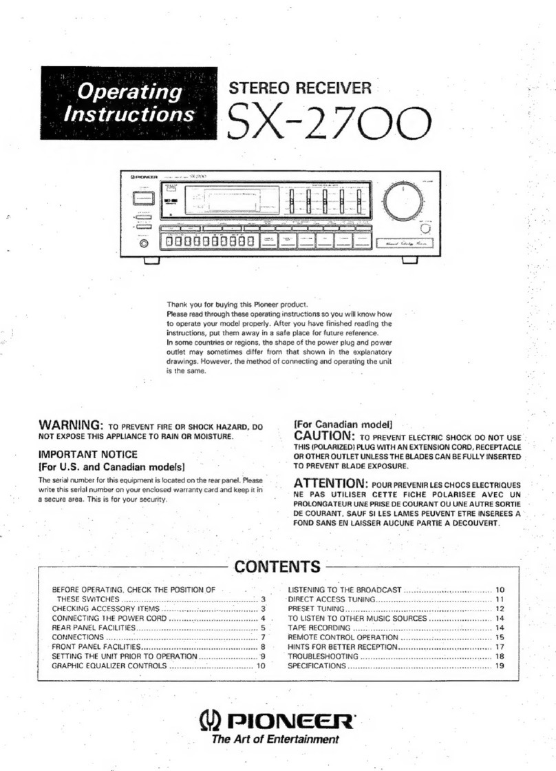
FRONT PANEL FACiliTIES
FRONT PANEL FACILITIES
SPEAKER BUTTONS
Each of speaker systems A, B, and C is connected to each
of output terminals A, B, and C.
By pushing the following:
SPKR-A .... Speaker systems A into operation
SPKR-B .... Speaker systems B into operation
SPKR-C .... Speaker systems C into operation
NOTES:
1. Whenanytwopairsofthebuttons(A+B B+C C+A)are
depressed, the corresponding
pairs of speaker systems ;"iIl
come into operation. However, operating all three button"
even though depressed at the same time is not possible.
2. Only when listening through headphones, press again the
SPKR button(s) in us" to OFF (undepressed) from the ON
position (pressed).
POWER SWITCH
Turn this switch ON but wait for some 3 to 6 seconds
during the silence of which the protection circuit elimi-
nates the unpleasant noise not imputed to a receiver fault.
PHONES (1 , 2) OUTPUT JACKS
Accept two pairs of headphones.
BASS CONTROLS
Adjust bass tone quality.
100Hz. . .. For the low frequencies below 400Hz.
Possible up to lOdB of increasing or
reducing at 100Hz in 2dB steps.
50Hz. . . . . . After adjustment by the 100Hz control
further adjust frequencies below 80Hz by
this control, if necessary. Possible up to
5dB of increasing or reducing in bass
response at 50Hz in 2.5dB steps.
LOW CUT, HIGH CUT BUTTONS
LOW. When the low-pitched rumble (turntable
motor or other source) is obtrusive, de-
press the LOW CUT button to ON. In no
interference, leave it undepressed (OFF).
When the high frequency scratch noise
(records or other source) is much, depress
this button to ON. In no interference
leave it undepressed (OFF).
HIGH
TONE SWITCH
When in the ON (up) position, this switch causes the
amplifier section to operate with a flat frequency regard-
less of the tone control settings. Use this switch to check
the audio characteristics of your listening room such as
when it is necessary to check the tone quality of phono
cartridges and speakers and also to particularly set the
tone controls to be assessed.
SIGNAL METER FM TUNING METER
While getting the SIGNAL meter needle going to the right
make fine adjustment with the FM TUNING meter whose
needle comes to the center (indicating the optimum
reception).
For AM and FM station tunings
AM tuning: Tune the dial pointer so that the SIGNAL
meter needle comes to the extreme right.
Both the SIGNAL and FM TUNING
meters work together. The optimum
point of the SIGNAL meter needle is the
same as in AM tuning. Then use the FM
TUNING meter.
FM tuning:
-FM STEREO INDICATOR
TUNING KNOB
.,~..
"'"'0 """"'" -do. ". .0'0
AUDIO MUTING BUTTON -20dB
Depress this button to mute the audio input to -20dB.
No need to turn down the VOLUME control on each
BALANCE CONTROL
Adjusts the balance between the sound volume from the
left and right speaker systems.
occasion for your convenience. DOLBY NR ADAPTOR SWITCH
When employing Dolby Noise Reduction Adaptor, depress
this DOLBY NR ADAPTOR to ON.
TREBLE CONTROLS
Adjust treble tone quality.
10KHz .. For the high frequencies above 2. 5kHz.
Possible up to 10dB of increasing or
reducing in treble response at 10kHz in
2d B steps.
.. After adjustment by the 10KHz control
further adjust frequencies above 12KHz
by this control, if necessary. Possible up
to 5dB of increasing or reducing in treble
response at 20kHz in 2.5dB steps.
20KHz
4CH ADAPTOR SWITCH
When using the 4-channel rear amplifier connected to the
4CH jacks on the rear panel, depress this 4CH ADAPTOR
to ON.
TAPE MONITOR (1 2) SWITCHES
Monitor the recorded sound while recording with a tape
deck. Also possible to play back tapes as follows:
1 . . . With a tape deck connected to the TAPE
1 jacks (REC and PB), either monitoring
of recording in progress or playing back is
possible.
. .. With a tape deck connected to the TAPE
2 jacks (REC and PB or REC/PB con-
nector), the same as in 1 above is possi-
ble.
TAPE DUPLICATE SWITCH
Leave this switch in the ON (down) position to duplicate
or edit a recorded tape using two tape decks. For normal
use, switch over to the OFF (up) position.
FUNCTION SELECTOR BUTTONS
For selecting the program source, push each button as
follows:
AM..
. . . ..
For AM broadcast reception.
For FM broadcast reception. The
STEREO indicator lights up when the
broadcast is in stereo.
PHONO 1 .. For operating a turntable connected to
the PHONO 1 input jacks.
For operating a turntable connected to
the PHONO 2 input jacks.
. . ..
For using a microphone. Not possible to
mix with other program source.
For listening to audio equipment (car-
tridge tape player, TV sound tuner, etc.
connected to the ALJX input jacks.
PHONO 2
MIC
AUX
DIMMER SWITCH
Dims the brightness of the indicator light. Press again to
restore full brightness.
FM MUTING BUTTON
Leave this button undepressed (in the ON position) while
tuning in FM stations. Inter-station noise may interfere
with FM reception while tuning between stations. To
suppress this noise, leave the MUTING button undepress-
ed (in the ON position). If the low signal strength is due
to distance from the transmitter or other influences
depress this button , at which the weak station will be
heard with the MUTING "OFF.
MODE BUTTON
Leave this button undepressed (if necessary, depress this
to release it when already depressed) for STEREO
playback. For MONO playback, depress it. In this case
stereo signals for left and right channels will be mixed into
mono signal which will be heard from the center of both
speaker systems.
LOUDNESS BUTTON
Depress this button to listen at low volume. The human
ear s frequency response varies according to the listening
volume. The depressed button compensates for hearing
response with emphasis on the bass and treble.
MIC INPUT JACKS
, R . . . .. For connecting the left and right channel
microphones.
NOTE:
Use the high impedance (above 20M2) with 6mm diam. phone
plug,.
VOLUME CONTROL
Governs both the volume of sound outputs from the
speaker systems and from the headphones.
